Bose ToneMatch T4S User manual

T4S/T8S ToneMatch®
Mixer
Owner’s Guide
Guía del propietario
Notice d’utilisation
Bedienungsanleitung
Manuale di istruzioni
Gebruikershandleiding
取扱説明書
用户指南
使用者指南

English - 5
Introduction
Product Overview
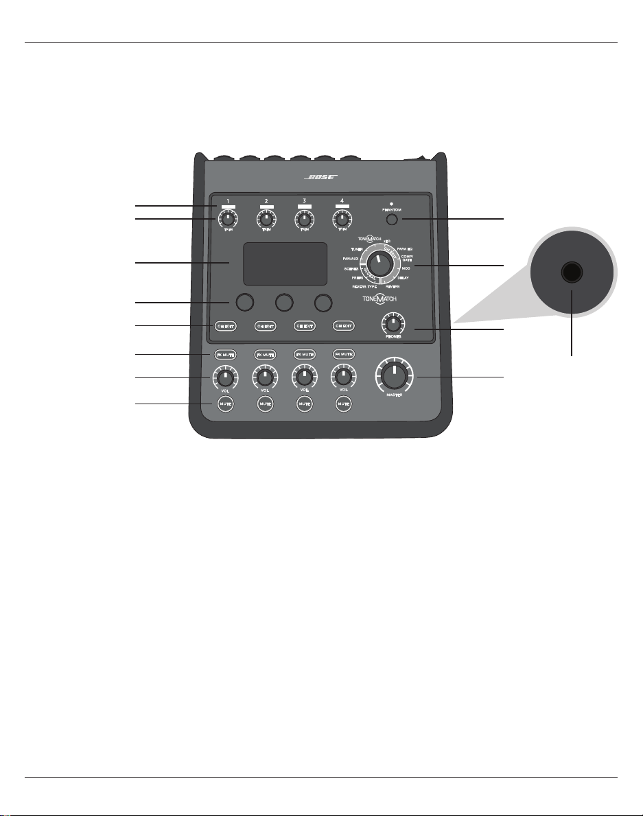
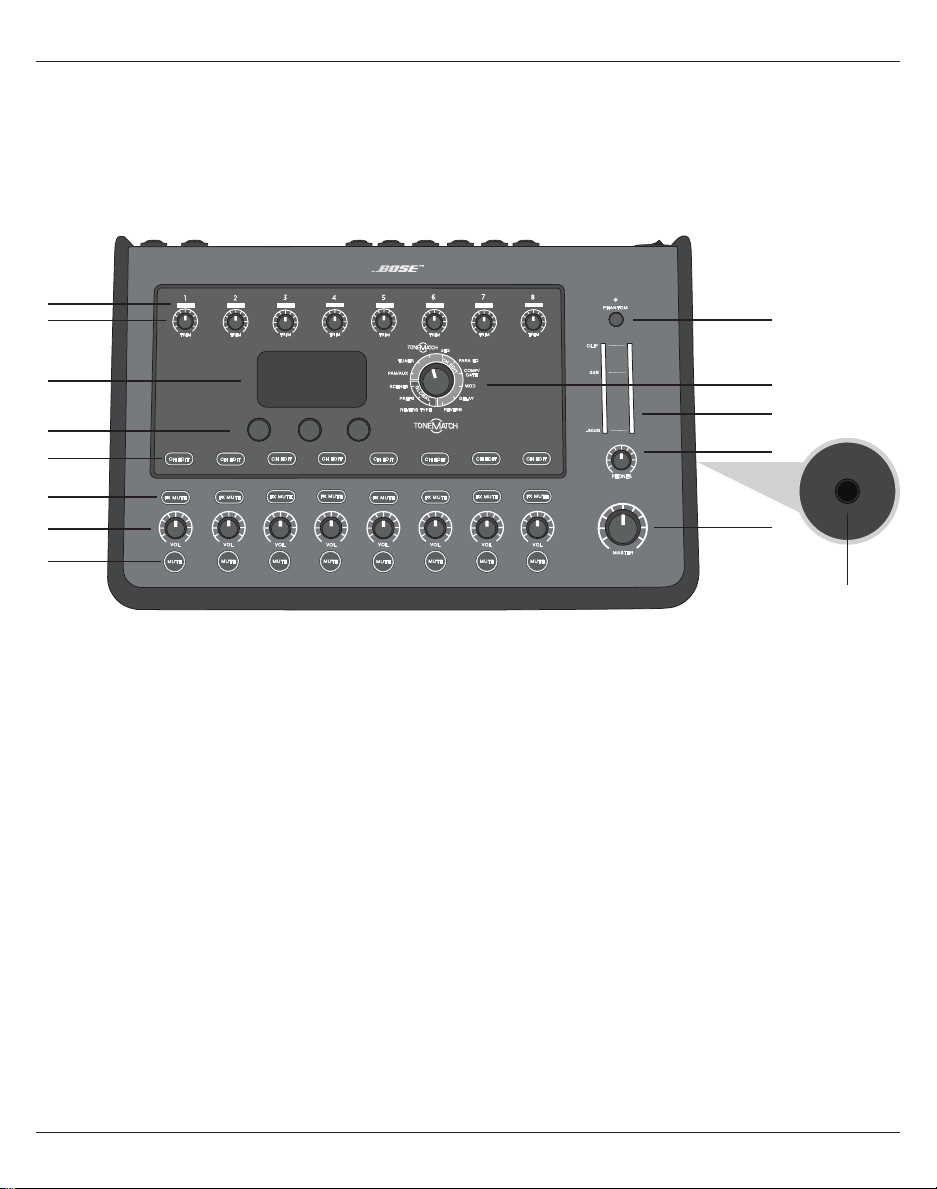
Take control of your music with T4S and T8S ToneMatch® mixers, compact 4 and 8 channel interfaces designed for performers.
Engineered with powerful DSP engines and intuitive user controls, they oer studio-quality EQ, dynamics and eects
processing. Sound great with integrated Bose® ToneMatch® processing and zEQ, especially when connected to a Bose L1 or F1
system for full end-to-end tonal control. Play confidently on stage with these rugged ToneMatch mixers using tactile controls,
easy-to-read LED displays and scene recall. ToneMatch mixers, the ultimate on-stage companions for performing artists.
Product Features
Powerful Audio Processing
• Updated, studio-quality eects with advanced digital
audio processing
• Eects include compressor, limiter, de-esser, noise gate,
chorus, flanger, phaser, tremolo, delay, and reverb
• Bose® ToneMatch® processing for natural-sounding vocals
and instruments
• zEQ focuses the sound of ToneMatch presets for eective
adjustments on the fly
• Independent ToneMatch, EQ, dynamics and eects per
channel
• Dedicated reverb for Aux sends, and a global shared
reverb for use across all channels
• Master output EQ helps compensate for venue acoustics
• Full end-to-end tonal optimization when used with Bose L1
and F1 systems
Seamless Live Control
• Tactile controls and indicators designed for live on-stage
use by musicians and DJs
• Fast-learning user interface
• Built-in tap tempo delay, chromatic tuner, and recallable scenes
• LED display and illuminated controls are easy to read and
use, even on dimly-lit stages
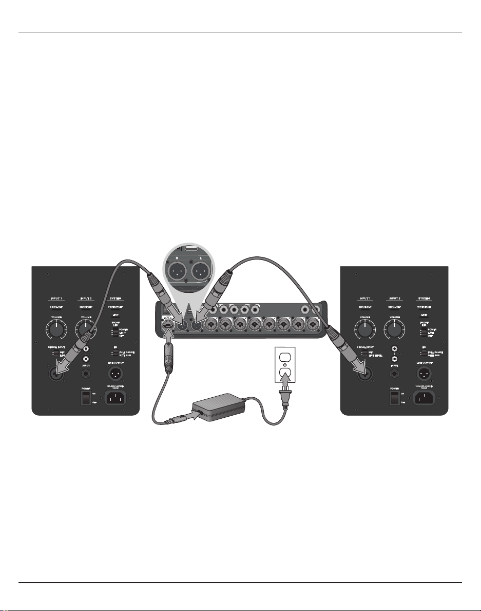
High-Density Connectivity
• Unprecedented connectivity and control in a small digital
stereo mixer
• Four (T4S) or eight (T8S) high-quality audio preamps with
XLR-combo jacks for microphones or instruments, and
switchable phantom power
• Two Aux inputs for additional sources two (T4S) or four
(T8S) Aux sends
• USB-A and -B for USB drive playback or PC/Mac interfacing
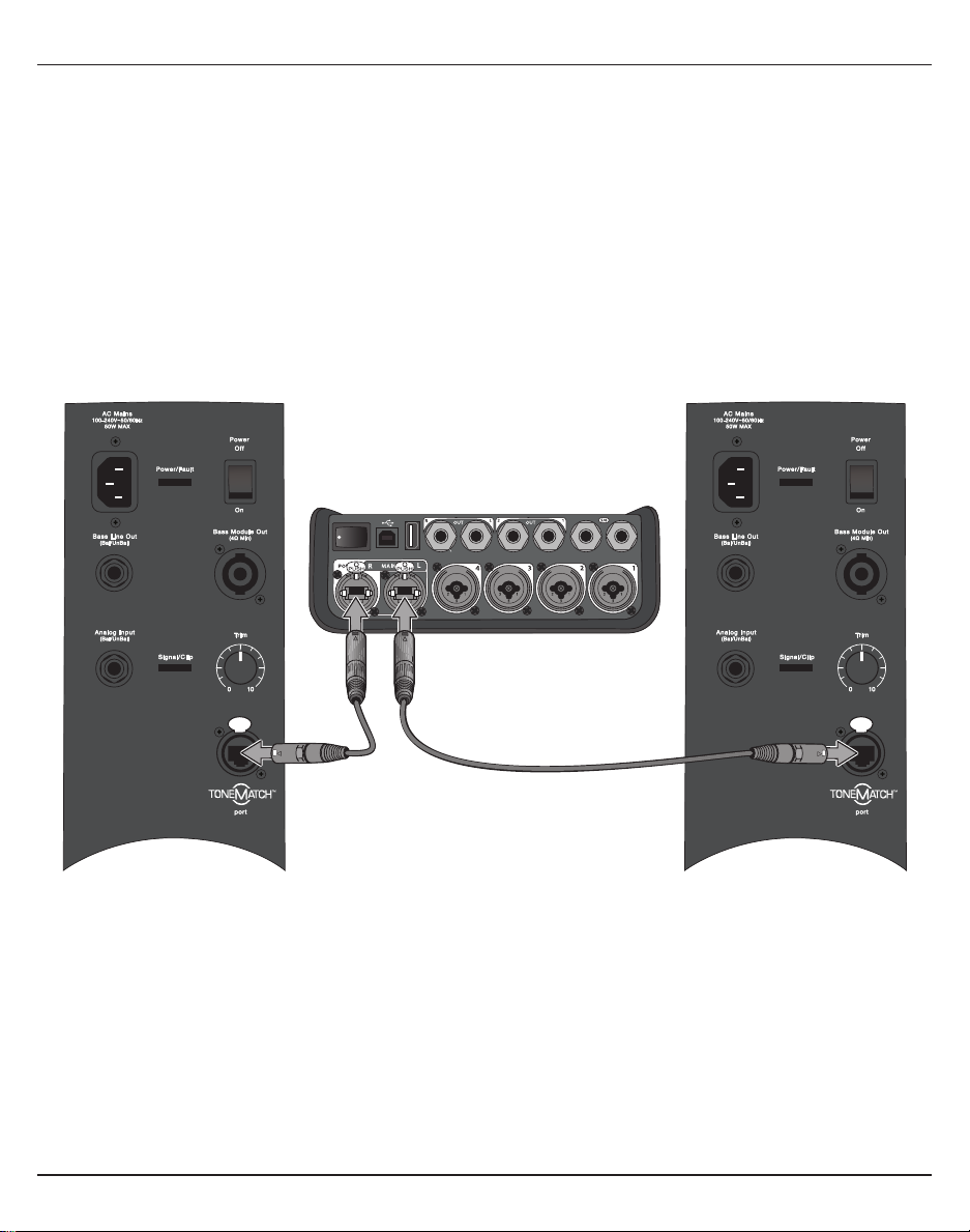
• ToneMatch outputs for digital audio and power (T4S only)
• Balanced ¼” TRS and XLR (T8S only) stereo outputs
• Independent headphone output
Convenient Gig-Ready Features
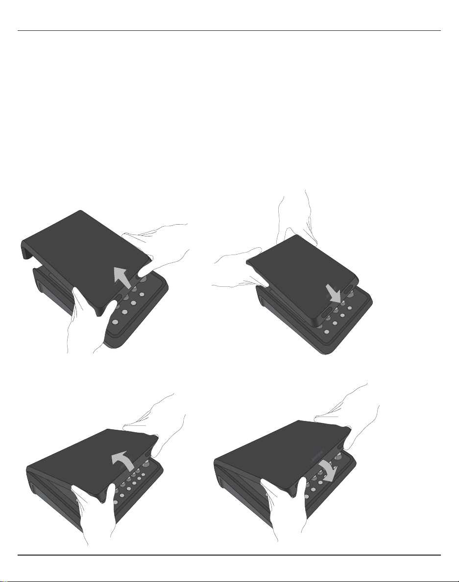
• Rugged enclosure with a protective magnetic cover to
protect controls and connectors
• Includes a ToneMatch cable for connecting to a Bose L1
Model II or L1 Model 1S system for digital audio and power
(T4S), or includes a universal power supply (T8S)
• Bottom insert allows you to use standard camera
mounting accessories to keep your ToneMatch mixer
within reach
T4S ToneMatch mixer and cover ToneMatch Cable
ToneMatch power supplyT8S ToneMatch mixer and cover
For a complete list of optional equipment and accessories, please visit www.Bose.com.
Unpacking
See the following table for what your mixer carton will include:
T4S
T8S

Control and Connection Panels
6 - English
T4S ToneMatch® Mixer
Control Panel
Figure 1. T4S Control Panel
qINPUT SIGNAL/CLIP LEDs(1-4) – Displays the input signal status in color:
Green: Indicates the presence of an input signal
Red: Indicates input source clipping
wTRIM CONTROLS (1-4) – Adjusts the input sensitivity for the respective channel.
eDISPLAY – Provides function menus and system information.
rEDITING CONTROLS – These three rotary/push-button controls allow you to select or adjust items/values
appearing on the display.
tCH EDIT BUTTONS (1-4) – Selects the channel you want to modify.
yFX MUTE BUTTONS (1-4) – Bypasses the Mod, Delay, and Reverb eects on the selected channel.
uVOLUME CONTROLS (1-4) – Adjusts the volume level for the respective channel.
iMUTE BUTTONS (1-4) – Silences the audio output for the respective channel.
oMASTER VOLUME CONTROL – Adjusts the overall output level.
aHEADPHONE VOLUME CONTROL – Adjusts the volume level of the headphone output.
sROTARY SELECTOR – Allows access to both global and channel-related parameters, which are adjusted
using the editing controls.
dPHANTOM POWER SWITCH – Applies +48V power to input channels 1-4. A red LED indicates that phantom
power is on.
fHEADPHONE JACK – For use with headphones only, with a minimum impedance of 24Ω.
q
w
i
u
y
t
r
e
d
s
a
o
f

English - 7
Control and Connection Panels
Figure 2. T4S Connection Panel
Connection Panel
qPOWER SWITCH – Turns the mixer on or o.
wUSB 2.0 TYPE-B – A USB interface that allows you to connect the mixer to your computer.
eUSB 2.0 TYPE-A – A USB interface that allows you to stream audio from your flash drive.
rANALOG L/R OUTPUT – Main analog output. Accepts ¼ TRS balanced or TS unbalanced cables.
tAUX OUTPUT – Two user-definable analog outputs. Can be configured for a pre-fader, post-EQ, and eects,
or post-fader output. Accepts ¼ TRS balanced cables.
yAUX IN – Analog input channels 5/6. Accepts ¼ TRS balanced or TS unbalanced cables for line-level
inputs. Can be used for stereo input signals.
uINPUTS 1-4 – Analog input channels 1-4. Accepts XLR balanced cables for microphones or ¼" TRS balanced
or TS unbalanced cables for high-impedance inputs, such as guitars.
iDIGITAL MAIN OUTPUT L – Connect digitally in stereo to two L1® Model 1S/II systems. Note: Only used in
stereo with Digital Main Output R.
oPOWER PORT/DIGITAL MAIN OUTPUT R – A digital output used by the L1 Model 1S/II system. Delivers
power to the T4S mixer from the L1 Model 1S/II power stand. Can also deliver power from an AC outlet via
a ToneMatch power supply (not included with the T4S). Accepts the included ToneMatch® cable.
CAUTION: Although the ToneMatch port accepts a standard RJ-45 connector, do NOT connect the T4S
to a computer or phone network.
USB AUDIO
M
( )
MONO
q w e r t y
uio

Control and Connection Panels
8 - English
T8S ToneMatch® Mixer
Control Panel
Figure 3. T8S Control Panel
qINPUT SIGNAL/CLIP LEDs(1-8) – Displays the input signal status in color:
Green: Indicates the presence of an input signal
Red: Indicates input source clipping
wTRIM CONTROLS (1-8) – Adjusts the input sensitivity for the respective channel.
eDISPLAY – Provides function menus and system information.
rEDITING CONTROLS – These three rotary/push-button controls allow you to select or adjust items/values
appearing on the display.
tCH EDIT BUTTONS (1-8) – Selects the channel you want to modify.
yFX MUTE BUTTONS (1-8) – Bypasses the Mod, Delay, and Reverb eects on the selected channel.
uVOLUME CONTROLS (1-8) – Adjusts the volume level for the respective channel.
iMUTE BUTTONS (1-8) – Silences the audio output for the respective channel.
oMASTER VOLUME CONTROL – Adjusts the overall output level.
aHEADPHONE VOLUME CONTROL – Adjust the volume level of the headphone output.
sSTEREO OUTPUT METER – Allows you to visually measure your output level.
dROTARY SELECTOR – Allows access to both global and channel-related parameters, which are adjusted
using the editing controls.
fPHANTOM POWER SWITCH – Applies +48V power to input channels 1-8. A red LED indicates that phantom
power is on.
gHEADPHONE JACK – For use with headphones only, with a minimum impedance of 24Ω.
q
w
i
o
g
a
s
d
f
u
y
t
r
e

English - 9
Control and Connection Panels
Figure 4. T8S Connection Panel
Connection Panel
qPOWER SWITCH – Turns the mixer on or o.
wUSB 2.0 TYPE-B – A USB interface that allows you to connect the mixer to your computer.
eUSB 2.0 TYPE-A – A USB interface that allows you to stream audio from your flash drive.
rANALOG L/R OUTPUT – Main analog output. Accepts ¼ TRS balanced and TS unbalanced cables.
tAUX OUTPUT – Four user-definable analog outputs. Can be configured for a pre-fader, post-EQ, and
eects, or post-fader output. Accepts ¼" TRS balanced or TS unbalanced cables.
yAUX IN – Analog input channels 9/10. Accepts ¼ TRS balanced or TS unbalanced cables for line-level
inputs. Can be used for stereo input signals.
uINPUTS 1-8 – Analog input channels 1-8. Accepts XLR balanced cables for microphones or ¼ TRS balanced
or TS unbalanced cables for high-impedance inputs, such as guitars.
iXLR STEREO OUTPUT – Stereo analog output. Accepts XLR balanced cables for stereo output.
oDIGITAL POWER PORT – For use w/ ToneMatch power supply (see “Connecting the ToneMatch® Power
Supply” on page 14).
Note: The T8S is NOT designed to connect digitally to the L1® Model 1S/II.
CAUTION: Although the ToneMatch port accepts a standard RJ-45 connector, do NOT connect the T8S
to a computer or phone network.
M
( )
MAIN OUT
USB AUDIO
MONO
q w e r t y
uio

10 - English
System Setup
Removing/Attaching the Cover
The T4S/T8S ToneMatch® mixer comes out of the carton with a cover installed on the top panel. The cover is
designed to protect the control panel while transporting or storing the mixer.
To remove the cover:
1. Place thumbs on notches on front of cover and slide cover forward.
2. Grab cover by the back and lift to remove it.
To attach the cover:
1. Slide cover over the mixer, from back to front.
2. The magnetized cover will engage on its own and secure itself to the mixer.
Figure 5. Removing and attaching the cover

System Setup
English - 11
Figure 6. Securing bracket to T4S Figure 8. Mounting T4S to tripod stand using bracket
Figure 7. Bracket attached to T4S
Mounting Options
The T4S/T8S comes with a ¼ (6 mm) mounting screw insert. This enables it to be mounted onto a number
of available products that include a ¼" (6 mm) mounting screw, including a camera tripod stand.
Mounting the T4S/T8S on a Camera Tripod Stand
1. Extend the camera tripod legs and secure at desired height.
2. Remove the bracket from the top of the camera tripod stand and secure the bracket to the bottom of the
T4S/T8S with the screw. Make sure the small indentation on the T4S/T8S and the bump on the bracket
are aligned. See Figure 6.
3. Secure the bracket with the T4S/T8S back onto the camera tripod stand. See Figure 8.
WARNING: Do not use the ToneMatch® T4S/T8S mixer with a tripod/stand that is unstable. The mixer
is only designed for use on a ¼" screw (6 mm), and the tripod/stand must be capable of supporting
a device with a minimum weight of 1.9 kg (4.1 lbs) and an overall size of 214 x 311 x 83 mm (8.4 x 12.25
x 3.25 inches). Using a tripod/stand that is not designed to support the size and mass of the T4S/T8S
mixer may lead to an unstable and hazardous condition that could result in injury.

12 - English
System Setup
Connecting the T4S via Digital Connection
1. Make sure the L1 Model 1S/II and T4S are powered o and the T4S Master volume control is set to
minimum.
2. Plug one end of the ToneMatch® cable into the Power port/Digital Main Output R on the T4S. Plug the
other end of the ToneMatch cable into the ToneMatch port on the power stand.
Note: To connect the T4S to two L1 Model 1S/II power stands, connect a second power stand to the Digital
Main Output L port on the T4S using a ToneMatch cable.
3. Turn on the mixer and then turn on the L1 Model 1S/II power stand.
4. Connect your instruments and adjust levels. Refer to “Optimizing Input Gain and Output Volume” on
page17.
Figure 9. Two L1 model II systems connected to a T4S via digital connection
USB AUDIO
M
( )
MONO
Note: The T8S cannot be connected digitally and cannot be powered by the L1 Model 1S/II.

System Setup
English - 13
Connecting the T4S/T8S via Analog Connection
1. Make sure the device you are connecting to and the T4S/T8S are powered o and the T4S/T8S Master
volume control is set to minimum.
2. Using XLR balanced cables, connect one or two devices to the XLR Stereo Outputs of your T8S (see
Figure 10).
Note: The T4S/T8S can be connected to a device via the Analog R Output port using a ¼" TRS cable (sold
separately). Plug the other end of the TRS cable into the Analog Input port of the device. To connect the
T4S/T8S to two devices, connect a second device to the Analog L Output port on the T4S/T8S using a ¼"
TRS cable.
3. Connect a ToneMatch® power supply to the Power port of the T4S/T8S and plug it into a live AC outlet.
Refer to “Connecting the ToneMatch® Power Supply” on page14.
4. Turn on the T4S/T8S mixer and then turn on the device.
5. Connect your instruments and adjust levels. Refer to “Optimizing Input Gain and Output Volume” on
page17.
Figure 10. Two F1 systems connected to a T8S via analog connection
M
( )
MAIN OUT
USB AUDIO
MONO
(
M
US
B AUDI
O
( )
M
M
AIN
O
UT
()
M

14 - English
System Setup
Connecting the ToneMatch® Power Supply
The ToneMatch power supply provides power for the T4S/T8S mixer.
1. Plug the power supply cable into the T4S/T8S Power port.
2. Plug one end of the AC power cord into the power supply.
3. Plug the other end of the power cord into a live AC power outlet.
4. Switch the T4S/T8S power switch to the ON position.
Note: Power supply included with T8S is required for operation of the T8S. Power supply is not included with
the T4S and is not required for operation of the T4S.
Figure 11. Connecting T4S to power supply

System Setup
English - 15
Connecting the T4S/T8S to Your Computer
The T4S/T8S provides a USB port for connecting it to a computer. This allows you to download performance
scenes to a computer or install system updates. Visit bosepro.link/tmu for details on updating your system.
When connected to a computer, you also can use the T4S/T8S as a general-purpose USB audio device for
recording/playback.
Note: The T4S/T8S operates at 48 kHz/24-bit. When using the T4S/T8S with recording software, you may
need to configure the software settings for 48 kHz/24-bit operation.
Note: Connecting the T4S/T8S to your computer requires a USB cable (Type A to Type B, not supplied).
1. Connect the mixer to a power source (ToneMatch® power supply for T4S/T8S or an L1 Model 1S/II for T4S only).
2. Plug one end of the USB cable into the mixer's USB 2.0 Type-B port (Figure 12).
3. Plug the other end of the USB cable into a USB port on your computer.
4. Turn on the mixer.
Figure 12. T4S-to-USB connection
ToneMatch port – To an L1 Model 1S/II
system or an ToneMatch power supply
Power switch
USB cable
(Type A to Type B)
To computer
USB port
Connecting a Flash Drive to the T4S/T8S
Plug in a USB 2.0/3.0 flash drive loaded with WAV/MP3 files into the USB 2.0 Type-A port to playback audio
tracks to your mixer.
Figure 13. Connecting a flash drive to the T4S

16 - English
Operation
Reading the T4S/T8S Display
The display provides you with an interface for operating the mixer. Figure 14 shows a sample of display
information and the basic operating conventions. The content of the display depends on the rotary selector
position.
Figure 14. Sample display and operating conventions
Ch 1
Type Tim
eM
ix
Digital 250ms 30%
Delay
Fdbk.
All Channels
*Bose Scene 01
Load Shared Save
Scenes
Identifies the
selected channel
Indicates that pressing the control
toggles between parameters
Displays visual representation of
the value of the parameter
Identifies the function accessed by
the rotary selector
Parameter names and
their settings/values
Rotary/pushbutton
controls
This symbol indicates
that rotating the control
changes the setting.
Asterisk indicates that
the loaded scene was
modified
Indicates that pressing
the control activates the
function

Operation
English - 17
Optimizing Input Gain and Output Volume
Getting a quality volume level from your system relies on the combined adjustments of input channel gain,
master volume, and channel volume. Do the following for each channel used.
1. Make sure the Master volume, Trim, and channel volume controls are set to minimum.
2. Adjust input channel Trim.
A. If applicable, adjust the volume of your instrument/source to the desired level.
B. Play your instrument/source at a performance level.
C. Slowly turn the Trim control clockwise until the signal/clip indicator glows green. If the indicator
flashes red or glows steady red, turn the Trim control counterclockwise to decrease the level.
D. Use the input level meters (page 28) in the Prefs menu to check your input levels
CAUTION: If you are using a device that requires phantom power (+48V), such as a condenser
microphone, depress the Phantom power switch before adjusting the Trim control.
Note: The input level meter in the Prefs menu can be helpful when adjusting the input Trim level (see
page 28).
3. Set the Master volume control at the 12 o’clock position.
4. Slowly turn the channel volume control clockwise until the volume reaches the desired level.
Input LevelPreferences
Ch 3
Ch 1
Ch 2
Ch 4
Menu Aux InReset
Peak level indicator
Input level indicator

18 - English
Operation
Using the Master Volume Control
The Master volume control adjusts the overall output level of the T4S/T8S ToneMatch®output and analog
Master output. During normal operation, it is recommended to keep the Master control set at the 12 o’clock
position. Once you have set volume levels for all channels, you can adjust the Master volume up or down from
this position.
Muting a Channel
The Mute buttons silence the audio for the respective channel.
• To mute a channel, press the Mute button once. The Mute button glows white to indicate that the channel is
muted. “CH MUTE” will appear on the display for the respective channel.
• Press the Mute button again to unmute the channel. The Mute button dims to indicate that the channel is not
muted.
Muting Channel Eects
The FX Mute buttons mute only the Mod, Delay, and Reverb eects on the respective channel. Muting eects
does not bypass ToneMatch presets, zEQ, Para EQ, and Comp/Gate settings.
• To mute eects on a channel, press the FX Mute button once. The FX Mute button glows white to indicate
that the channel eects are muted. “FX MUTE” will appear on the display for the respective channel.
• Press the FX Mute button again to unmute the channel eects. The FX Mute button dims to indicate that the
channel eects are not muted.
Ch 1
Category
Utility
ToneMatch
CH MUTE
Flat
Preset
Ch 1
Category
Utility
ToneMatch
FX MUTE
Flat
Preset

Operation
English - 19
Using the Rotary Selector
The rotary selector provides access to the functions of the ToneMatch® mixer output. Figure 15 provides a
summary of the nine channel-related functions and the three global functions. The following pages describe
how to adjust each function.
Figure 15. Rotary selector
Channel Functions
qPan/Aux –Provides access to pan, aux ins, and aux outs.
wTuner – Provides tuning information for an instrument playing into the selected channel.
eToneMatch – Provides access to proprietary ToneMatch presets designed for specific instruments and
microphones.
rzEQ – As part of the selected ToneMatch preset, zEQ provides controls to adjust low/mid/high frequencies
that are within the range of your instrument or microphone.
tPara EQ – Provides parametric EQ controls per channel.
yComp/Gate – Provides access gate, compression, limiter, de-esser, and kick drum presets with adjustable
parameters.
uMod – Provides access to several modulation eects such as chorus, flanger, phaser, and tremolo.
iDelay – Provides access to three types of delays and tap-tempo delay.
oReverb – Applies reverb to a selected channel and can be sent to mains or aux.
Global Functions
aReverb Type – Applies a selected type of reverb to all master output channels or aux sends.
sPrefs – Allows access to several system utilities.
dScenes – Allows you to save and load performance scenes (a snapshot of the complete state of the unit).
e
o
y
d
r
a
u
q
t
si
w

20 - English
Operation
Editing the Sound of a Channel
The CH Edit functions allow access to settings that aect selected channels. The CH Edit functions are Pan/
Aux, Tuner, ToneMatch®, zEQ, Para EQ, Comp/Gate, Mod, Delay, and Reverb.
To edit a channel:
1. Press the CH Edit 1,2,3, 4,(T4S and T8S) 5, 6, 7, or 8(T8S only) button. The selected channel will be
viewable in the upper-left corner of the display.
2. Select one of the CH Edit functions using the rotary selector.
3. Adjust the settings for that function using the following instructions.
Note: You can only edit one channel at a time. Pressing a CH Edit button enables editing for the selected
channel only.
Using the Pan/Aux Functions
Use the Pan/Aux function to route audio to either the master out L or R, control aux in, or aux send.
Using Pan
Use the Pan control to send each channel to its separate space in a stereo mix.
1. Press or rotate the left editor control and select Pan from the menu.
2. Rotate the Pan control to adjust the line output from L to R.
Aux Input 5/6 (9/10)
Use Aux Input 5/6 (9/10) to input a line-level stereo source, such as a mobile device.
1. Press or rotate the left control and select Aux In 5/6 from the menu.
2. Rotate the 5 Lvl or 6 Lvl control to adjust the signal level of either channel 5 or channel 6.
3. Press the 5 Lvl to switch to 5 Pan; press the 6 Lvl control to switch to 6 Pan. Rotate the Pan control to
adjust the pan from L to R.
Ch 1
Menu Pan
Pan
Pan
Ch 1
Menu 5 Pan 6 Lvl
Aux In 50%
Aux Input 5/6
6 Pan5 Lvl

Operation
English - 21
Routing Input Signals to the Aux Outputs
The Aux function allows you to route signals to two Aux outputs (T4S only) or four Aux outputs (T8S only)
for various signal processing, recording, and sound reinforcement applications. The signal level is adjustable
for each of the available Aux outputs:
Note: To mute the Aux output, press the Level control. Press it again to unmute.
1. Press or rotate the Menu control and select an Aux Send.
2. Rotate the Level control to adjust the signal level of the selected channel.
3. Rotate the Tap control to scroll through the tap menu and highlight the desired tap point.
A. Dry: After Preamp – The completely dry (no processing) signal is routed directly from the preamp
stage.
B. Pre: With EQ & Fx – The signal is routed from the preamp stage with applied processing.
C. Post: After Fader – The signal is routed after the Channel volume control with applied processing.
4. Press the Select control to select the tap point, or press the Cancel control to exit with no change. The
name of the currently selected tap point appears in bold type.
Ch 1
Menu Tap
Aux
1P
re
Level
50%
Aux 1 Output
Using the Tuner
An independent tuner is available on each input channel. The display indicates the note being played at the
bottom of the screen. As you tune, a pitch indicator appears on the display, showing you whether the note is
sharp or flat. Adjust the pitch of your instrument so the cursor aligns itself with the center of the screen.
Note: For silent tuning, press the Mute button for the applicable channel.
Use the Transpose feature to change the reference pitch up or down by two half steps. Or precisely dial in
your tuning using the reference pitch.
Ch 1
b#
A3
Tuner
Pitch indicator

22 - English
Operation
Ch 1
Category
Vocal Mics
ToneMatch
Handheld Mics
Preset
Handheld Mics
Headworn Mics
High Gain: Bright
High Gain: Normal
SelectCancel
Ch 1
Category
Utility
ToneMatch
Flat
Preset
Ch 1
Category
Vocal Mics
ToneMatch
Headworn Mics
Preset
Vocal Mics
Utility
Electric Guitars
Acoustic Guitars
Select Cancel
Rotate Press
PressRotate
Selecting a ToneMatch® Preset
The ToneMatch function allows you to select a ToneMatch preset for your instrument or microphone.
This proprietary technology optimizes system equalization to preserve the natural sound of your specific
instrument or microphone. They are organized into categories and independently selected for each channel.
1. Rotate the Category control to access the list of categories and highlight your choice.
2. Press the Select control to select your choice, or press the Cancel control to exit the list with no change.
3. If you pressed Select, rotate the Preset control to access the list of presets and highlight your choice.
4. Press the Select control to select your choice, or press the Cancel control to exit the list with no change.
Ch 1
Low Mid
Handheld Mics
High
0.0db 0.0db 0.0db
zEQ
Adjusting zEQ
The zEQ function is part of the ToneMatch preset technology. It allows you to adjust low/mid/high
frequencies that are within the range of your instrument or microphone.
To adjust zEQ, rotate the control under the corresponding frequency band.
Note: To bypass an individual frequency band, press the corresponding control. Press it again to activate.

Operation
English - 23
Adjusting Para EQ
The Para EQ function provides three parametric equalizations centered on a user-specified frequency within
the range of 50 Hz to 16 kHz.
Note: To bypass the Para EQ settings, press the Select control. Press it again to activate.
1. Press or rotate the Select control and select Para EQ band 1-3.
2. Rotate the Level control to adjust the boost/cut level from -15 dB to +15 dB.
3. Rotate the Freq control to adjust the center frequency from 50 Hz to 16 kHz.
4. Press the Freq control to switch to Width. Rotate the Width control to adjust the width of the bell curve
around the center frequency from 0.20 octave to 5.00 octave.
Ch 1
Select Level
B3
Freq
PEQ 1 -3.4dB 250.0Hz
Parametric EQ
Width
Using Compressor/Gate Functions
The Comp/Gate function provides access to gate, compression, limiter, de-esser and kick drum presets with
adjustable parameters.
Note: To bypass the Comp/Gate settings, press the Type control. Press it again to activate.
Note: Only one eect per channel.
1. Rotate the Type control to access the list of Comp/Gate eects and highlight your choice:
A. Compressor 1: Light – Compressor featuring a preset low-compression ratio with variable threshold
and gain parameters. Works well as a general-purpose compressor for most instruments and
microphones that require minimal level control.
B. Compressor 2: Medium – Compressor featuring a preset moderate compression ratio with variable
threshold and gain parameters. Works well with basses, guitars, keyboards, and vocals requiring
subtle level control.
C. Compressor 3: Heavy – Compressor featuring a preset high compression ratio with variable threshold
and gain parameters. Works well with loud instruments (like horns and drums), as well as strong
vocals that require more aggressive level control.
D. Limiter – Hard limiter featuring a preset ratio (∞:1) with variable threshold and gain parameters. Works
well with very loud instruments, such as drums, to prevent signal peaks from overloading the channel.
Ch 1
Type Thresh Speed
Gate -80.0dB 50%
Comp/Gate
Ramp
Other manuals for ToneMatch T4S
2
Table of contents
Other Bose Music Mixer manuals