CHAPTER 2
-Installation and wiring-
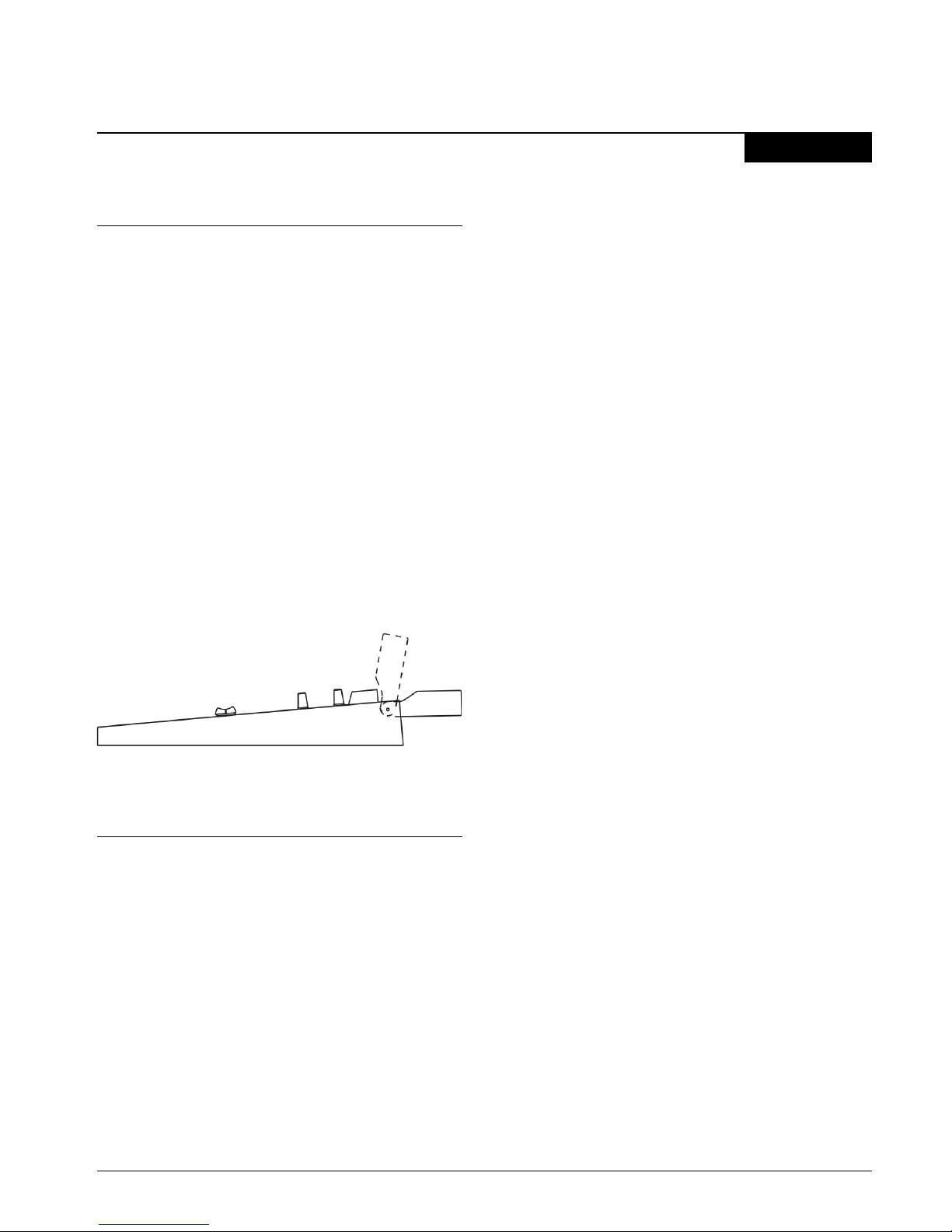
2.1 On installation
Installation of Solidyne audio console doesn’t pre-
sent particular problems. However, keep in mind the
basic rules for all professional audio installations.
The inputs and outputs of the D-816 series incorpo-
rate DIN-5 multi-pin connectors for stereo balanced
inputs (provided with the console). You can acquire
the Solidyne wiring kit (MNG816), which incorporates
all the cables and connectors needed for installing
D816.
For console grounding use the rear side GND bronze
tip with a 2mm cable to a good buried cooper bar.
2.1.1 Parasitic signals
All unwanted signals that appear in audio lines usu-
ally consider parasitic signals. A common type are
denominated umming, low frequency signals (multi-
ples of 50/60 Hertz) caused by the interaction of
electromagnetic fields coming from the AC line.
When the interference source is a magnetic field (ge-
nerally originated in a supply transformer) the resul-
tant interference will be denominated electromagne-
tic umming. When the interference is due to such
electric potentials as cables that take supply tensi-
ons, that are elevated in comparison with the audio
signals present in the circuit, you will be in presence
of electrostatic umming. The distinction is not me-
rely academic, because the resolution of a problem
supposes the knowledge of the noise type to apply
the correct solution.
Examples: To minimize t e reception of electromagnetic
umming in t e wires, remember t e following rule: "THE
AREA AMONG TWO AUDIO WIRES WILL BE MINIMUM."
It implies t at t e cables will be tied very close, like t e
s ielded twisted pair audio cables. T ey s ould pass far
away from any transformer or devices t at manage ig -
intensity currents. Is important to remember t at a wire
can be good s ielded, but if is conductors don’t complete
t e conditions of minimum area it will be susceptible to
take magnetic umming.
Other parasitic signals are: AC HUM, RADIO FRE-
QUENCY and CROSSTALK. As hum noises like the
radio frequency are originated by electromagnetic fi-
elds of high frequency; the first ones are originated
by disturbances due to the connection and discon-
nection of equipment’s to the AC line, the seconds
ones are generated by communications transmitters
or industrial equipment. If these signals penetrate
into audio lines, with sufficient intensity, can surpass
the action of the special protection filters, and to rea-
ch some sensible part of the input stages. In that
case, the interfering signals can be demodulated and
already turned audio signal, and will be amplified by
the rest of the system. It is fundamental, therefore, to
maintain the interference within reduced margins. It
is obtained avoiding very long audio lines, with aerial
sections or that pass near of transformers or RF
transmitters. For protection against very high fre-
quencies is advisable to use double shielded cables,
guarantied by the manufacturer.
CROSSTALK is the reception of signals coming from
other lines of audio. This, like all unwanted noise, it
can be supposed controlled when its level is below
the level of the system residual noise. Then, all con-
siderations mentioned for the case of buzz are valid.
2.1.2 RF interference (Hum)
D-816 consoles have numerous internal protections
against RF fields, for the AM and FM broadcasting
band. When the transmission station is installed cor-
rectly, there will be no interference problems, still
with FM equipment of 50 KW installed in the terrace
of the radio station. Nevertheless, when the antenna
is badly positioned with respect to the Studio or has
severe SWR problems, then it does not have the mi-
nimum value of field intensity, downward. Or maybe
there is a faulty ground connection, then, strong
standing waves will appear on the cables of the Stu-
dio that can induce high electrical currents inside the
audio console.
Symptoms: If the interference takes place at the
A.M. band, the sound transmitted by the A.M. radio
will be listened in the loudspeakers on background
(or at buses PGM, REC). In case of FM transmissi-
ons, the interference inside the console demodulates
the A.M component of the FM carrier; (usually hum
from power supply) causing background humming,
because in many transmitters of FM, the final output
stage is not powered with stabilized tension. There-
fore, if console D816 presents humming, please
make a test shutting down the transmitter a few se-
conds to check if the problem disappears. Someti-
mes, an FM transmitter with the output stage badly
SOLID NE D·816 broadcast console Page 7