BOSSCO SNR24023 User manual

FormNo.MSC25235RevA
Owner'sManual
V-BladePlowKit
SnowratorMAG
PartNo.SNR24023—SerialNo.400000000andUp
Registeratwww.bossplow.com.
OriginalInstructions(EN)*MSC25235*
BOSSProductslimitedconsumerwarrantyandBOSS
Productscommercialwarrantypoliciesarelocatedat
www.bossplow.com.
Patentswww.ttcopats.com.
Introduction
Note:ThisplowattachestotheSnowratorMAG.
TheV-bladeplowisintendedtobeusedonaBoss
stand-on,multi-purposemachine.Thebladeis
designedtohydraulicallychangeitsangleasneeded
forsnowremoval.Usingthisproductforpurposes
otherthanitsintendedusecouldprovedangerousto
youandbystanders.
Readthisinformationcarefullytolearnhowtooperate
andmaintainyourproductproperlyandtoavoid
injuryandproductdamage.Youareresponsiblefor
operatingtheproductproperlyandsafely.
Visitwww.bossplow.comforproductsafetyand
operationtrainingmaterials,accessoryinformation,
helpndingadealer,ortoregisteryourproduct.
Wheneveryouneedservice,genuineBOSSparts,or
additionalinformation,contactanAuthorizedBOSS
DealerorBOSST echnicalService(1-800-286-4155)
andhavethemodelandserialnumbersofyour
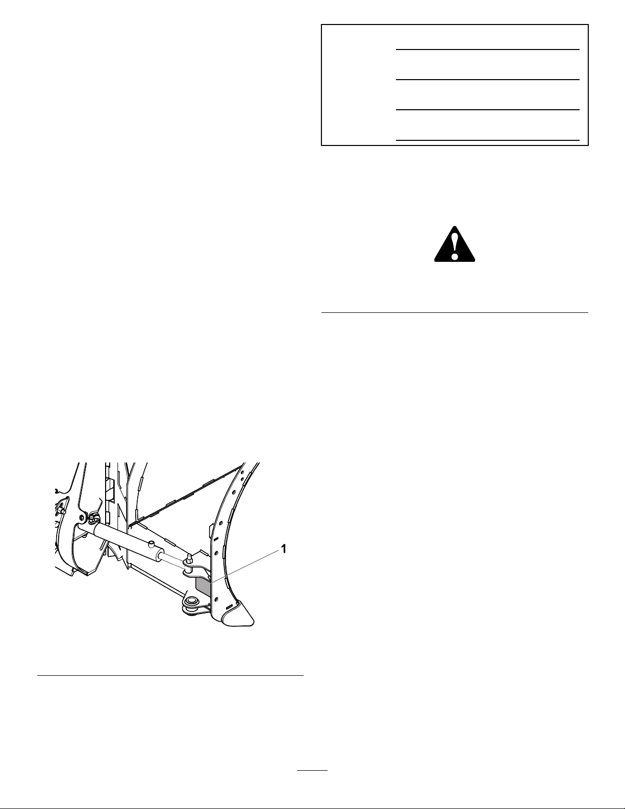
productready.Figure1identiesthelocationofthe
modelandserialnumbersontheproduct.Writethe
numbersinthespaceprovided.
g373489
Figure1
1.Modelandserialnumberlocation
Date
Purchased
ModelNo.
SerialNo.
BladeCrate
SerialNo.
Thismanualidentiespotentialhazardsandhas
safetymessagesidentiedbythesafety-alertsymbol
(Figure2),whichsignalsahazardthatmaycause
seriousinjuryordeathifyoudonotfollowthe
recommendedprecautions.
g000502
Figure2
1.Safety-alertsymbol
Thismanualuses2wordstohighlightinformation.
Importantcallsattentiontospecialmechanical
informationandNoteemphasizesgeneralinformation
worthyofspecialattention.
©2022—BOSSProducts
P .O.Box787
IronMountain,MI498012
Contactusatwww.bossplow.com.
PrintedintheUSA
AllRightsReserved

Contents
Safety.......................................................................3
Preparation.........................................................3
Operation............................................................3
SafetyandInstructionalDecals..........................4
Setup........................................................................5
MountingthePlow..............................................5
ProductOverview.....................................................6
Controls.............................................................6
Operation..................................................................8
MountingthePlow..............................................8
RemovingthePlow.............................................8
OperatingTips...................................................8
Maintenance.............................................................9
RecommendedMaintenanceSchedule(s).............9
...........................................................................9
Maintenance..........................................................9
ReplacingtheCuttingEdge....................................9
Storage...................................................................10
StoringthePlow...............................................10
RemovingthePlowfromStorage......................10
Troubleshooting.......................................................11
Safety
Improperuseormaintenancebytheoperatoror
ownercanresultininjury.Toreducethepotential
forinjury,complywiththesesafetyinstructions
andalwayspayattentiontothesafety-alert
symbol,whichmeans:Caution,Warning,or
Danger—personalsafetyinstruction.Failureto
complywiththeinstructionmayresultinpersonal
injuryordeath.
Preparation
•ReadtheOwner’sManualbeforeoperatingor
servicingtheplow.
•Ensurethatonlytrainedpersonnelinstallsand
performsmaintenanceontheequipmentand
hydrauliccomponents.
•Alwayswearappropriatepersonalprotective
equipmentwhenloading,unloading,andservicing
theplow.
Operation
•Usea500kg(1/2ton)minimumliftingdeviceto
moveheavyplowcomponents.
•Donotexceed8km/h(5mph)whileoperating.
•Neverputanypartofyourbodybetweentheplow
andthevehicle.
•Wearappropriateclothing,includinghearingand
eyeprotection,protectivegloves,andsubstantial,
slip-resistantfootwear.Tiebacklonghair,secure
looseclothing,anddonotwearloosejewelry.
•Whentransportingtheplow,ensurethatitis
properlysecured.Instructionsareavailableat
www.bossplow.com.
•Whentransportingthevehicle,positiontheplow
soasnottoblockyourvisionorheadlights.
•Donotchangethebladepositionwhentraveling.
•Alwayslowerthebladewhenthevehicleisnotin
use.
•Donotoperatethemachinewhileill,tired,or
undertheinuenceofalcoholordrugs.
•RefertotheOwner’sManualforproperparking
procedures.
•Turnthevehicleandplowoffbeforelling,
servicing,orcleaningit.
•Donotclimbintoorrideontheplow.
•Keepyourhands,feet,andclothingawayfrom
movingpartsandmountingpoints.
•Useyourfullattentionwhileoperatingthe
machine.Donotengageinanyactivitythat
3
causesdistractions;otherwise,injuryorproperty
damagemayoccur.
•Donotoperatetheplowwithin8m(25ft)of
bystanders.
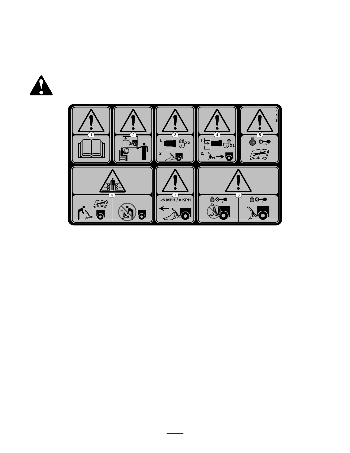
SafetyandInstructionalDecals
Safetydecalsandinstructionsareeasilyvisibletotheoperatorandarelocatednearanyarea
ofpotentialdanger.Replaceanydecalthatisdamagedormissing.
decalmsc23037
MSC23037
1.Warning—readtheOwner’sManual.5.Warning—shutofftheengine,removethekey,andreadthe
Owner’sManualbeforeperformingmaintenance.
2.Warning—alloperatorsshouldbetrainedbeforeoperating
themachine.
6.Crushinghazard—donotstandbetweentheplowandvehicle
duringmaintenance.
3.Warning—couplermustbelockedbeforeplowing.7.Warning—donotexceed8km/h(5mph)whenplowing.
4.Warning—couplermustbeunlockedtoremovetheplow.8.Warning—lowertheplowwhenthevehicleisnotinuse.
4
Setup
MountingthePlow
1.Parkthemachineonalevelsurface.
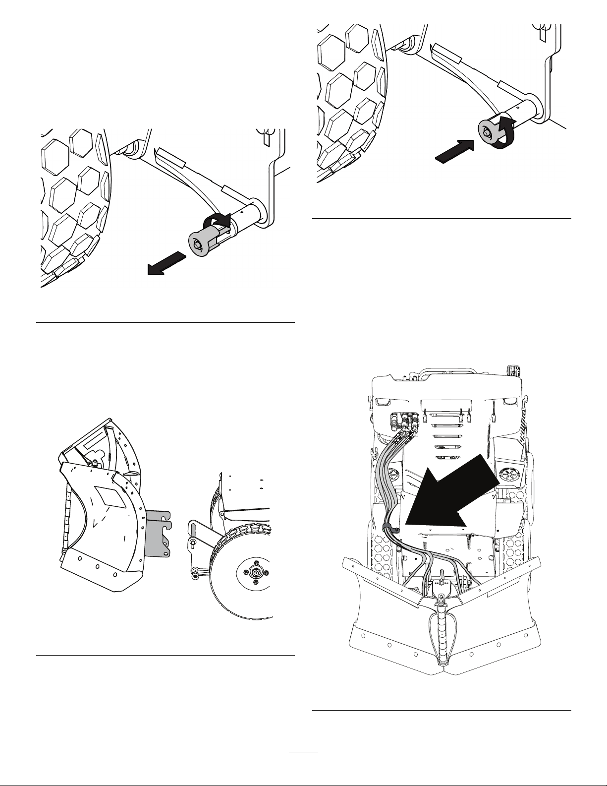
2.Pullthecouplerpinsoutwardandrotate90°to
lockinthedisengagedposition.
g373475
Figure3
3.Makesurethatthehydraulichosesdonotblock
theplowattachmentpoint.
4.Startthemachine.
5.Slowlydriveforwarduntilthecouplermeetsthe
plowhooks.Raisethecouplertohookitonto
theplow.
g381690
Figure4
6.Rotatethecouplerpin90°sothatitengages
withtheplowassembly.
Note:Ensurethatthecouplerpinalsoinserts
throughtheholeinthepinchannelontheplow
coupler.
g373477
Figure5
7.Lowertheattachmentcoupleruntiltheplow
restsontheground.
8.Shutoffthemachineengine,waitforallmoving
partstostop,ensurethattheparkingbrakeis
engaged,andremovethekey.
9.Routethehydraulichosesfromtheplow,
throughthehosestrap,totheconnectionson
themachine
Note:Theleftlowowhosesarecoloredyellow
andconnecttothecenterports.
g381686
Figure6
10.Startthemachine.
5

11.Usethecontrolstomovetheplowinall
directionstocyclethehydraulicuid.
12.Lowertheplowandshutoffthemachine.
13.Checkandllthehydraulicuid;refertothe
machineOwnersManual.
WARNING
Hydraulicuidescapingunderpressure
canpenetrateskinandcauseinjury.
•Ifhydraulicuidisinjectedintothe
skin,itmustbesurgicallyremoved
withinafewhoursbyadoctorfamiliar
withthistypeofinjury.Gangrenemay
resultifthisisnotdone.
•Keepyourbodyandhandsawayfrom
pinholeleaksornozzlesthateject
high-pressurehydraulicuid.
•Usecardboardorpapertond
hydraulicleaks.
•Safelyrelieveallpressureinthe
hydraulicsystembeforeperforming
anyworkonthehydraulicsystem.
•Makesurethatallhydraulic-uid
hosesareingoodcondition,and
allthatthehydraulicconnections
andttingsaretightbeforeapplying
pressuretothehydraulicsystem.
ProductOverview
Controls
g381687
Figure7
1.Anglelevers2.Attachmentcouplerlever
•Usetheattachmentcouplerlevertoraise,lower,
oroattheplow.
g381689
Figure8
6
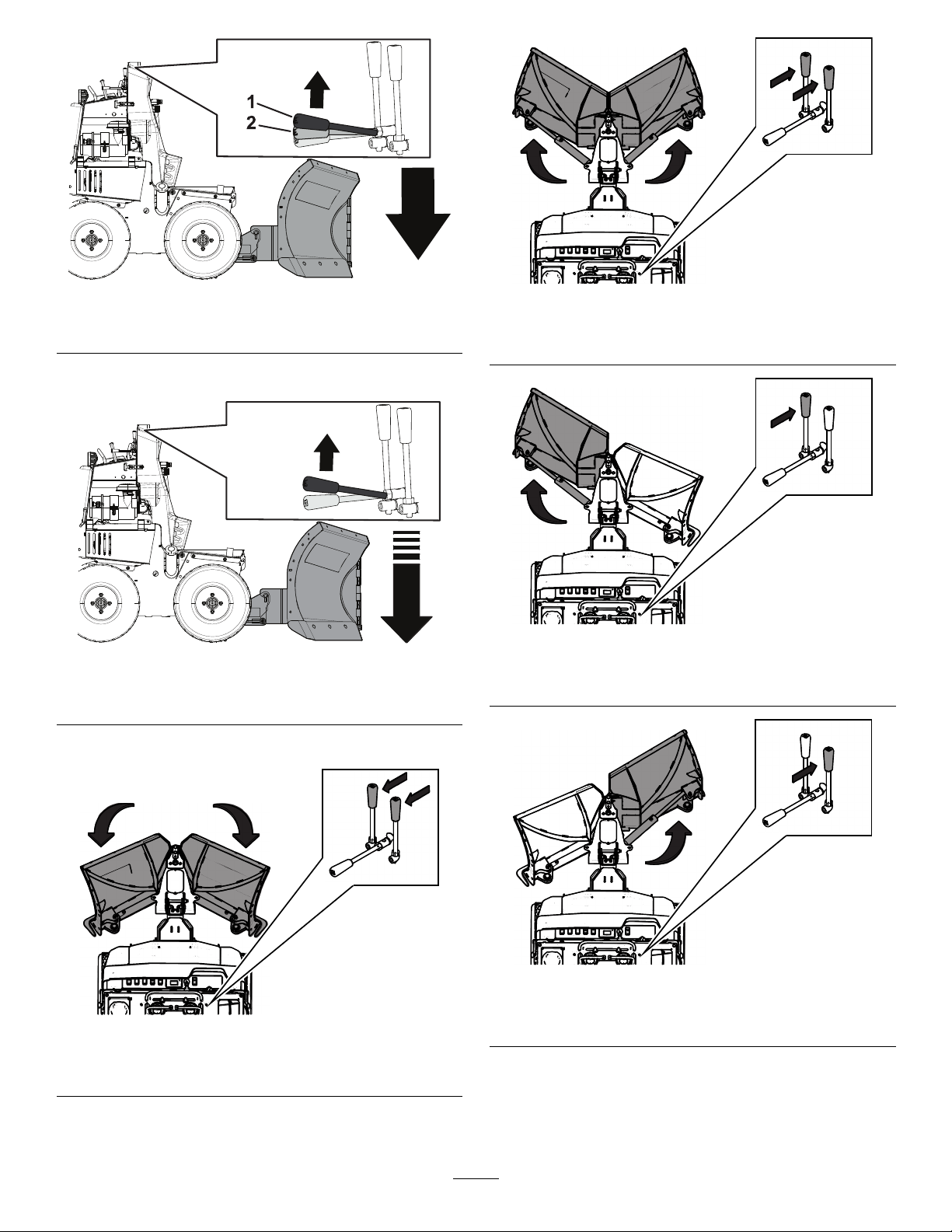
g381688
Figure9
1.Float2.Lower
Note:Donotplowforwardindownforce.
g381948
Figure10
DownForce
•Usetheangleleverstoangletheplowblades.
g373490
Figure11
Vposition
g373488
Figure12
Scoopposition
g373487
Figure13
Rightangle
g373483
Figure14
Leftangle
7
Operation
MountingthePlow
RefertotheMountingthePlow(page5)section
above.
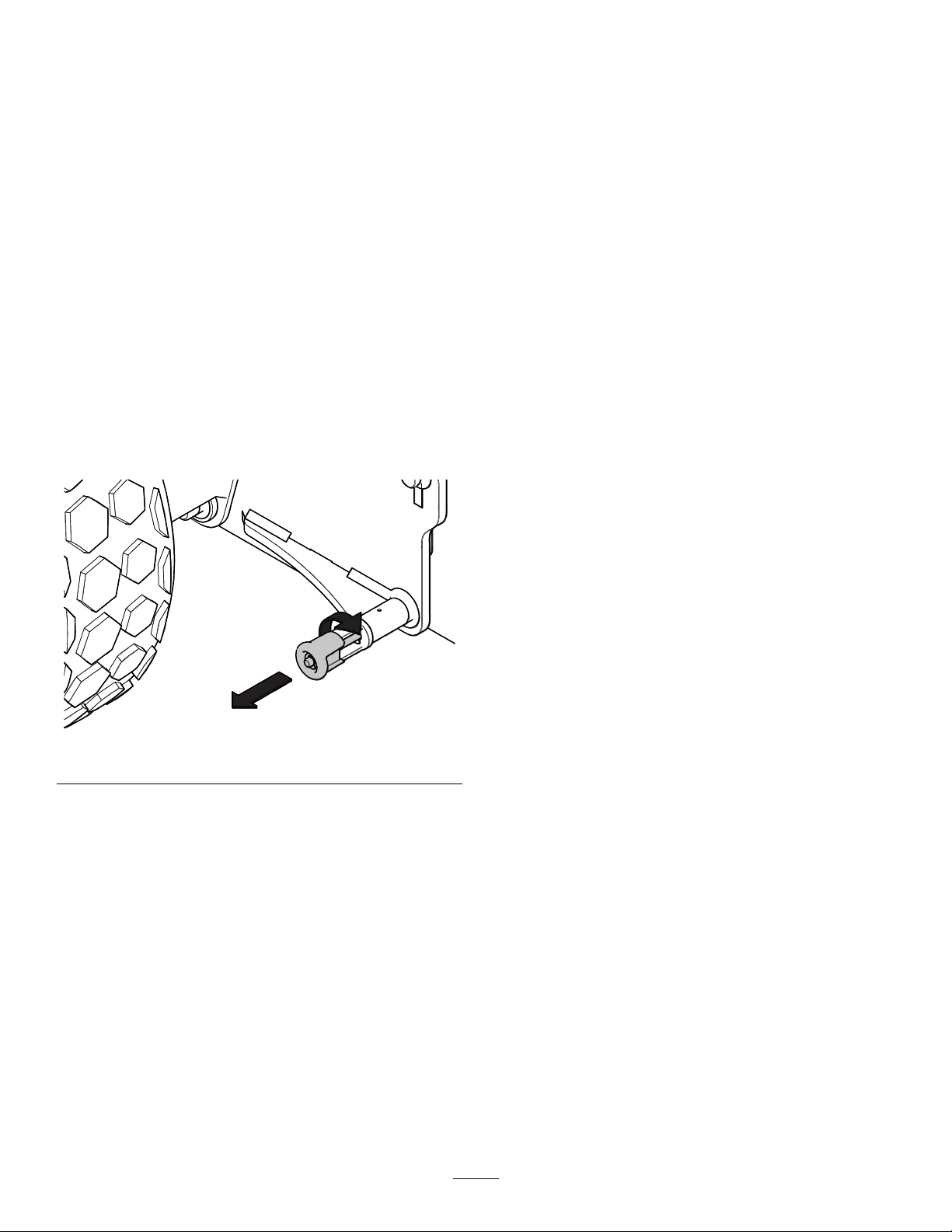
RemovingthePlow
1.Stopmachineonalevelsurface.
2.PlacetheplowintheVposition
3.Lowertheplowuntilthecuttingedgeis2.5to5
cm(1to2inches)fromtheground.
4.Shutofftheengine,waitforallmovingpartsto
stop,engagetheparkingbrake,andremove
thekey.
5.Disconnectthehydraulics.
6.Pullthecouplerpinsandturnit90°untiltheplow
isdisconnectedfromthemachine.
g373484
Figure15
7.Startmachine,lowerattachmentcoupler,and
slowlybackawayfromplow.
8.Arrangethehydraulichosesanddisconnectsso
thattheyarenotrestingontheground.
OperatingTips
•Becomefamiliarwiththeareayouareplowing;
hiddenobstructionssuchascurbsandpipescan
damageyourplowormachine.
•Donotletsnowaccumulate;alwaysplowwiththe
storm.
•Lowertheplowwhennotinusetopreventpossible
injury.
•Alwaysplowatasafespeedincaseyouhithidden
obstructions.
•Whentransportingthemachine,donotblockyour
visionwiththeplow.
•Donotchangetheplowpositionwhileplowing.
•Ensurethatthekickstandisraisedbeforeplowing
topreventdamagetotheplowormachine.
•Formoreplowingtips,visitwww.bossplow.com.
8

Maintenance
RecommendedMaintenanceSchedule(s)
MaintenanceService
IntervalMaintenanceProcedure
Aftertherst2hours•Tightenallhardware.
Beforeeachuseordaily
•Checkthehydrauliccylinders.
•Checkthehydrauliclinesandhoses.
•Checkallfasteners,pins,retainers,nuts,andbolts.
•Checkthecuttingedgeforwear.
Beforestorage
•Lightlysandandusetouch-uppaintonpaintedareasthatarescratched,chipped,
orrusted.
•Greasethehydrauliccylinderrods.
•Lightlysandandusetouch-uppaintonpaintedareasthatarescratched,chipped,
orrusted.
Maintenance
•Checkthehydrauliclinesandhosesdailyfor
leaks,kinkedlines,loosemountingsupports,wear,
loosettings,weatherdeterioration,andchemical
deterioration.Makeallnecessaryrepairsbefore
operating.
•Checkthehydrauliccylindersdailyforleaks,rust,
orpittingontherods.Makeallnecessaryrepairs
beforeoperating.
•Checkthecuttingedgedailyforwear.Replacethe
cuttingedgeifitisworndown.
•Checkallfasteners,pins,retainers,nuts,andbolts
dailytoensurethattheyaresecure.T orquethem
totheappropriatevalueiftheyareloose.
ReplacingtheCutting
Edge
Note:Replacementhardwareisavailablethroughan
AuthorizedBossDealerorBossTechnicalService.
1.Removeanddiscardthe3nutsand3washers
holdingthecuttingedgetotheblade.
g373480
Figure16
2.Removeanddiscardthe3carriageboltsand
cuttingedge.
9

g373481
Figure17
3.Installnewcuttingedgewithnewhardware.
Torqueto101N·m(75ft-lbs).
Storage
StoringthePlow
1.Drivetheplowtoyourstoragelocationand
removetheplow;refertoyourmachine
Operator’sManual.
2.Greaseanyexposedmetalonthehydraulic
cylinderrods.
3.Lightlysandandusetouch-uppaintonpainted
areasthatarescratched,chipped,orrusted.
RemovingthePlowfrom
Storage
1.Checkthetorqueofallfasteners;tightenas
necessary.
2.Checkthehydrauliclinesandhosesforcracks
orleaks.
3.Checkthecuttingedgeforwear.
4.Lightlysandandusetouch-uppaintonpainted
areasthatarescratched,chipped,orrusted.
5.Attachtheplowtothemachine;refertoyour
machineOperator’sManual.
6.Movetheplowthroughitsrangeofmotionto
checkthehydrauliccylinderrods.
10

Troubleshooting
ProblemPossibleCauseCorrectiveAction
1.Acylinderorhoseisbad.1.Checkthecylinders,hoses,andall
ttingsforleaks.Tightenanyloose
connections.Replaceanydamaged
components.
Theplowwingsretractwhileplowing.
2.Thepressurereliefvalveisbad.2.Checkthepressurereliefvalve,
locatedontheSnowratorMAGtraction
unit.Ifthevalveiscontaminated,clean
orreplaceit.
1.Thehydraulicuidlevelislow.1.Checkthehydraulicuidlevel;referto
yourSnowratorMAGOwner'sManual.
2.Thepressurereliefvalveisbad2.Checkthepressurereliefvalve,
locatedontheSnowratorMAGtraction
unit.Ifthevalveiscontaminated,clear
orreplaceit.
3.Acylinderorhoseisbad.3.Checkthecylinders,hoses,andall
ttingsforleaks.Tightenanyloose
connections.Replaceanydamaged
components.
Theplowwing(s)donotextend,retract,
ortheymoveslowly.
4.Thehydrauliccouplingsarenot
attachedtothevehicle.
4.Connecttheplowhydraulicstothe
vehiclehydraulics.
Theleftwingextends/retractswhenthe
rightcontrolleverisactuated,orvice
versa.
1.Thehosesareconnectedtothewrong
controlvalves.
1.Disconnectthehosesandconnect
themtothecorrectcontrolvalves.
1.Ahoseisbad.1.Checkhosesforleaks.Tightenany
looseconnections.Replaceany
damagedcomponents.
2.Acylinderisbad.2.Replacethecylinder.
Oilleaksfromthehydrauliccylinders.
3.Thecylinderrodispitted.3.Polishtherodwithsteelwool.Replace
thecylinderisthepittingistoobad.
Thebladetripstooeasily.1.Thetrip-springsneedadjustment.1.Tightenthesprings.Replacethemif
theyaredamaged.
Theplowdoesnotfollowthecontourof
theground.
1.Theattachmentcouplerleverisnotin
theoatposition.
1.Ensurethattheattachmentcoupler
leverisintheoatpositionwhile
plowing.
11

Table of contents
Other BOSSCO Snow Blower Accessories manuals


