Bostit CAP2045ST-OL User manual

BEFORE OPERATING THIS COMPRESSOR, THE USER SHOULD STUDY THIS MANUAL TO UNDERSTAND AND
FOLLOW THE SAFETY WARNINGS AND INSTRUCTIONS. KEEP THESE INSTRUCTIONS WITH THE COMPRESSOR
FOR FUTURE REFERENCE. IF YOU HAVE ANY QUESTIONS, CONTACT YOUR BOSTITCH REPRESENTATIVE OR
DISTRIBUTOR.
ANTES DE USAR ESTE COMPRESOR, EL USUARIO DEBE ESTUDIAR ESTE MANUAL PARA ENTENDER Y SEGUIR
LAS ADVERTENCIAS DE SEGURIDAD Y LAS INSTRUCCIONES. CONSERVE ESTAS INSTRUCCIONES CON EL
COMPRESOR PARA REFERENCIA FUTURA. SI TIENE ALGUNA PREGUNTA, DIRÍJASE AL REPRESENTANTE O AL
DISTRIBUIDOR.
AVANT D’UTILISER LE COMPRESSEUR, L’UTILISATEUR DOIT LIRE CE MANUEL AFIN DE COMPRENDRE ET DE
RESPECTER LES AVERTISSEMENTS ET CONSIGNES DE SÉCURITÉ. GARDER CES INSTRUCTIONS AVEC LE
COMPRESSEUR POUR RÉFÉRENCE ULTÉRIEURE. POUR DE PLUS AMPLES INFORMATIONS, COMMUNIQUER
AVEC VOTRE REPRÉSENTANT OU DISTRIBUTEUR BOSTITCH.
158590REVA 6/02
OPERATION and MAINTENANCE MANUAL
MANUAL DE OPERACIÓN Y DE MANTENIMIENTO
MANUEL D’OPÉRATION ET DE MAINTENANCET
D’ENTRETIEN
CAP2045ST-OL
AIR COMPRESSOR
COMPRESOR DE AIRE
COMPRESSEUR D’AIR

INTRODUCTION
Congratulations on your purchase of a High Performance BOSTITCH Portable Air Compressor.
This compressor has been designed to provide compressed air to power various pneumatic
tools - including pneumatic fastening tools.
Before assembling, operating or maintaining this air compressor, users must read and
understand the information contained in this owner’s manual. Carefully review the Rules for
Safe Operation section in this owner’s manual and fully understand all warnings.
Danger indicates an imminently hazardous situation which, if not avoided, WILL
result in death or serious injury.
Warnings indicate a potentially hazardous situation which, if not avoided,could
result in death or serious bodily injury.
NOTICE!: Notice indicates important information that if not followed correctly could result in
damage to equipment.
INDEX
Safety Instructions ..........................................................................................................................2
Rules for Safe Operation ..........................................................................................................3, 4
Electrical Grounding Instructions ............................................................................................5, 6
Features...............................................................................................................................................7
Operation Instructions.....................................................................................................................8
General Maintenance .................................................................................................................8, 9
Trouble Shooting guide .................................................................................................................10
Warranty ...........................................................................................................................................11
NOTE:
Bostitch compressors have been engineered to provide excellent customer satisfaction and
are designed to achieve maximum performance.
2

RULES FOR SAFE OPERATION
Be Educated:
All users must read and fully understand all information contained in this owner’s manual
before assembling, operating, or maintaining this air compressor.
Avoid Moving Parts:
When the compressor is plugged into an electrical source and the pressure switch is in the
ON/AUTO position, this compressor will cycle automatically.
• Never touch any moving parts.
• Keep all body parts, hair, clothing, and jewelry away from moving parts.
• Never operate the air compressor without all guards and shrouds in place.
• Never stand on the compressor.
Attachments and Accessories:
For any attachment or accessory you will be using with this compressor, the maximum
allowable recommended pressure should be clearly marked on the product or should be
clearly noted within the operations manual. Exceeding the pressure rating of these
attachments (including, but not limited to: air tools, air operated accessories, spray guns, air
hose, air hose connections, tires and other inflatables) could cause them to fly apart or
explode and could result in serious injury.
• Never exceed the maximum allowable pressure recommended by the manufacturer of any
attachment or accessory you use with this compressor.
Personal Protection:
The employer and/or user must ensure that proper eye protection is worn. Eye protection
equipment must conform to the requirements of the American National Standards Institute
ANSI Z87.1-1989 and provide both frontal and side protection.
NOTICE!: Non-side shielded spectacles and face shields alone do not provide adequate
protection. Eye protection conforming to ANSI Z87.1-1989 will always be marked “Z87”.
CAUTION: Additional Safety Protection will be required in some environments. For
example, the working area may include exposure to noise level which can lead to hearing
damage. The employer and user must ensure that any necessary hearing protection is
provided and used by the operator and others in the work area. Some environments will
require the use of head protection equipment. When required, the employer and user must
ensure that head protection conforming to ANSI Z89.1-1986.
• Always wear eye protection.
• Wear proper hearing and head protection.
• Compressed air blast must never be aimed at anyone. Compressed air can cause bodily
injury and can propel loose particles and small objects at high speed.
• Keep children away from area of operation.
Transporting:
Use the handle to move the compressor. Do not drag or pull the compressor by the power
cord or air hose. Always disconnect the air compressor before transporting.
3

RULES FOR SAFE OPERATION (continued)
Air Tanks:
Due to condensation associated with the process of compressing air, moisture will build up
inside your compressor’s air tank. Drain tanks of moisture daily (See General Maintenance).
Failure to drain moisture from the tanks properly could lead to the formation of rust and
thinning of the steel tank.
WARNING: FAILURE TO REGULARLY DRAIN TANK MAY CAUSE TANK CORROSION AND
RISK OF TANK EXPLOSION, RESULTING IN SERIOUS INJURY. TO AVOID RISK OF TANK
FAILURE DURING USE, DRAIN TANK AFTER EACH USE OR EVERY FOUR HOURS OF
OPERATION TO PREVENT CONDENSATION BUILD-UP AND TANK CORROSION.
WARNING: DO NOT PERFORM WELDING OR REPAIR OPERATIONS ON THE AIR TANK OF
THIS COMPRESSOR. WELDING ON THE AIR COMPRESSOR TANK CAN SEVERELY IMPAIR
TANK STRENGTH AND CAUSE AN EXTREMELY HAZARDOUS CONDITION. WELDING ON
THE TANK IN ANY MANNER WILL VOID THE WARRANTY.
Ventilation:
WARNING: RISK OF FIRE OR EXPLOSION - DO NOT SPRAY FLAMMABLE LIQUID IN A
CONFINED AREA. SPRAY AREA MUST BE WELL VENTILATED. DO NOT SMOKE WHILE
SPRAYING AND DO NOT SPRAY WHERE SPARK OR FLAME IS PRESENT. KEEP
COMPRESSORS AS FAR FROM SPRAYING AREA AS POSSIBLE.
Risk of Burns:
All air compressors generate heat, even operating under normal conditions. Bostitch
compressors have been designed to reduce the risk of burns by limiting access to tubes and
cylinder head parts. In areas where tubes are exposed, a protective sheathing has been
added to the tubes to reduce risk; however, risk of burns does exist.
• To avoid serious burns, never touch the cylinder head parts or tubing during or immediately
after operation.
4

ELECTRICAL GROUNDING INSTRUCTIONS:
This product should be electrically grounded. In the event of an electrical short circuit,
grounding reduces the risk of electrical shock by providing an escape wire for electrical
current. This product is equipped with a cord having a grounding wire with an appropriate
grounding plug. The plug must be plugged into an outlet that is properly installed and
grounded in accordance with all local codes and ordinances.
DANGER: IMPROPER INSTALLATION OF THE GROUNDING PLUG CAN RESULT IN A RISK
OF ELECTRIC SHOCK. If a repair or replacement cord is necessary, do not connect the
grounding wire to either flat blade terminal. Check with a qualified electrician or serviceman,
if the grounding instructions are not completely understood or if there is doubt as to whether
this product is properly grounded. Do not modify the plug provided. If the supplied plug does
not fit the outlet, have the proper outlet installed by a qualified electrician.
This product is shipped for use on a nominal 120-volt circuit, and has a grounding plug that
looks like the plug in sketch A. A temporary adapter that looks like the adapter illustrated in
sketches B and C may be used to connect this plug to a 2-pole receptacle as shown in sketch
B, if a properly grounded outlet is not available. The temporary adapter should be used only
until a properly grounded outlet (sketch A) can be installed by a qualified electrician. The
green colored rigid ear, lug, or like extending from the adapter must be connected to a
permanent ground such as a properly grounded outlet box cover. Whenever the adapter is
used, it must be held in place by a metal screw.
The motor of this compressor has a thermal overload protector in the motor winding. If the
motor should overheat, the overload protector will shut the motor off. When the temperature
returns to normal, the motor will restart automatically.
NOTICE! Do not stop the compressor by pulling out the plug. Use only the Auto/Off switch,
which operates a pressure relief valve on the compressor. If the compressor is plugged in
with the switch in the “Auto” position, the compressor may have trouble restarting against
the high pressure which could cause excessive heat build up and could damage the motor.
Safety Valve:
This compressor is equipped with a safety valve that is set to avoid over-pressurization of the
air tanks. This valve is factory pre-set at 140 PSI and will not function unless tank pressure
reaches this pressure. DO NOT ATTEMPT TO ADJUST OR ELIMINATE THIS SAFETY DEVICE.
ANY ADJUSTMENTS TO THIS VALVE COULD CAUSE SERIOUS INJURY. If this device
requires service or maintenance, see an Authorized BOSTITCH Service Center.
5
Grounding Pin
Metal Screw
Grounding Pin
Grounding Means
Cover of
grounded
outlet box
AB
C

ELECTRICAL GROUNDING INSTRUCTIONS: (continued)
DUTY CYCLE:
To ensure long life of your BOSTITCH air compressor, do not operate on more than a 50% duty
cycle. If this air compressor pumps air more than 50% of one hour, then the compressor’s
capability is less than the air delivery required by the application. Always match the air
volume requirements of the attachment or accessory with the air volume delivery of the
compressor.
Notice!: BOSTITCH does not recommend the use of extension cords with compressors. The
use of an extension cord can result in the loss of voltage supplied to the compressor which
could prevent the compressor from starting. For optimum performance, plug the compressor
directly into an outlet and increase the length of airline as needed.
If an extension cord must be used, use these guidelines:
Distance Needed Recommended Gauge
Less than 25 ft. 12 Gauge
25 - 50 ft. 10 Gauge
Greater than 50 ft. Not Recommended
6

FEATURES OF THE BOSTITCH CAP2045ST-OL
A. Pressure Switch: The pressure switch is
the activation mechanism that is used to start
and stop the compressor. When the switch is
moved to the “AUTO” position, the motor and
pump will compress air until tank pressure
reaches the upper limit of the factory set
operating pressure. When tank pressure falls
below the factory set “cut in” pressure, the
compressor will again automatically start to
compress air.
B. Tank Pressure Gauge: The tank pressure
gauge indicates the air pressure that is
present in the tank in PSI (lbs/sq. in.).
C. Regulated Pressure Gauge: The regulated pressure gauge indicates the amount of
pressure that is allowed into the two discharge lines (E) according to the setting of the
regulator.
D. Regulator Knob: The regulator knob is used to adjust the air pressure that is available at
the two discharge lines. The discharge air pressure is increased by turning the knob
clockwise and decreased by turning the knob counter clockwise.
E. Discharge Lines: This compressor is equipped with two discharge lines. These lines extend
from the control panel as 1/4” female NPT to allow the end user to attach the appropriate size
fitting for the application.
F. Drain Cocks: Pull-style or twist style valves that drain moisture from the tanks when they
are opened.
G. Oil Drain: By removing the sight glass plug, oil can
be drained from the compressor crankcase. The
opening is tapered so that a small receptacle can be
placed under the opening to cleanly catch the oil.
H. Oil Fill: When adding oil to the unit, it is poured into
this opening. The opening is designed to act as a
funnel to make filling easier and cleaner.
I. Sight Glass: This oil drain plug is see-through so that
the user can quickly and easily verify the oil level prior
to operation.
7
A
B
C
D
E
F
G
H
I

OPERATION INSTRUCTIONS
Pre-Start Procedures:
1. Inspect the compressor for any damaged components. Do not operate if compressor is
damaged.
2. Check oil level in the compressor pump (See “Checking Oil Level”).
3. Verify that the tanks have been drained and are clear of any moisture or dirt (See
“Draining Tank”).
4. Verify that the air filter is securely in place (See “Air Filter Installation”).
Start-Up Procedures:
1. Verify that the Auto/Off switch is in the Off position.
2. Verify that the tank air pressure is at 0 PSI.
3. Attach the air hose to the discharge line.
4. Plug the unit into a properly grounded outlet.
5. Turn the Auto/Off switch to Auto. The compressor will automatically cycle on and off to
keep the tank pressure maintained .
6. Adjust the pressure regulator to the proper pressure setting required for the air tool.
Shut-Off Procedures:
1. Turn the Auto/Off switch to the Off position.
GENERAL MAINTENANCE
Service and Maintenance:
Prior to performing service and maintenance to the compressor, always disconnect all
accessories and attachments from the unit and disconnect the compressor from the
electrical source. When replacing parts, only use Genuine BOSTITCH replacement parts.
Checking the pump Oil Level - Using the Sight Glass:
1. Verify that the compressor is turned off and on a level surface.
2. Observe the oil level through the clear sight glass that is located at the base
of the crankcase.
3. If oil is visible to the middle of the sight glass, then the oil level is acceptable.
Checking the pump Oil Level - Using the Dipstick:
1. Verify that the compressor is turned off and on a level surface.
2. Remove the dipstick from the oil fill port.
3. Wipe oil off the dipstick.
4. Reinsert dipstick fully into the oil fill port for a few moments.
5. Remove the dipstick and observe the oil level, which should be no
higher than the “MAX” mark and no lower than the “MIN” mark.
8

GENERAL MAINTENANCE (continued)
Changing the Oil:
1. Verify the compressor is turned Off.
2. Place a small catch basin under the oil drain port (an 8oz. cup will work fine).
3. Remove the dipstick.
4. Remove the oil drain plug/sight glass.
5. Allow the oil to drain into the catch basin - tilting the compressor toward the
drain plug is beneficial.
6. Insert the oil drain plug/sight glass into the oil drain port.
7. Add 7.5 oz of 30w non detergent oil to the crankcase.
8. Insert dipstick.
Draining Tanks - Pull-Style Drain Cocks:
1. Verify that the compressor is turned Off.
2. Holding the handle, tilt the compressor toward the drain cocks so that they are positioned
at the bottom of the tank.
3. Pull the cord to open the drain valves.
4. Hold until all moisture has been removed.
5. Release when done.
Draining Tanks - Twist-Style Drain Cocks:
1. Verify that the compressor is turned Off.
2. Holding the handle, tilt the compressor toward the drain cocks so that they are positioned
at the bottom of the tank.
3. Turn the drain cocks to open the valve.
4. Keep the compressor tilted until all moisture has been removed.
Air Filter Installation:
1. Remove the plastic plug from the side of the pump head.
2. Remove the air filter from the box.
3. Screw the air filter into the threaded opening on the side of the pump head.
Checking/Cleaning the Air Filter:
WARNING: COOLING FINS, PUMP HEAD, AND SURROUNDING PARTS ARE VERY HOT. DO
NOT TOUCH.
1. Verify that the compressor is turned Off.
2. Remove the cap by turning clockwise.
3. Remove the filter element from the cap.
4. Clean filter pad with soap and water as necessary. If the filter becomes clogged or
damaged, replace it.
WARNING: NEVER CLEAN AIR FILTER WITH A FLAMMABLE LIQUID OR SOLVENT.
EXPLOSIVE VAPORS MAY ACCUMULATE IN THE AIR TANKS AND CAUSE AN EXPLOSION,
RESULTING IN SERIOUS INJURY OR DEATH.
5. Insert filter element into the cap.
6. Place the filter cap onto the filter base and turn counter-clockwise to attach.
ANY OTHER SERVICE SHOULD ONLY BE PERFORMED BY AN AUTHORIZED
BOSTITCH SERVICE CENTER
9

TROUBLE SHOOTING GUIDE
NOTE: REMOVE POWER SOURCE AND DRAIN TANK PRESSURE PRIOR TO MAKING ANY REPAIRS OR ADJUSTMENTS.
Problem Probable Cause Correction
Unit will not run Tank pressure exceeds “cut in” pressure Once pressure drops below “cut in” pressure, the unit will start.
Extension cord causing excessive amp draw Check guidelines for proper cord gauge
(use of extension cords is not recommended).
Fuse or circuit tripped Replace fuse or breaker
Unit not turned on or not plugged in Check pressure switch and verify that it is in the Auto position.
Verify that unit is plugged in.
Air filter plug not removed Remove air plug and install Air filter.
Cold weather conditions Place compressor in warmer environment for at least 30 minutes
(typically temperatures below freezing) then try restarting.
Air leaks at fittings Fittings loose Tighten fitting. Check with soapy water. DO NOT OVER TIGHTEN.
Air leak at pressure switch Clogged check valve Remove and clean check valve
Unit will not build pressure Application requires excessive air demand Reduce demand on compressor
Loose head Tighten bolts on head
Blown gasket Remove head and check for
broken or deformed gasket. Replace if needed.
Unit will not build pressure Worn or broken valves Remove head and replace valves.
Air leak at tank or air tank Damaged air tank
welds. WARNING: DO NOT DRILL INTO , WELD OR OTHERWISE MODIFY AIR TANK.
DAMAGED OR MODIFIED TANKS CAN RUPTURE. REPLACE TANK IMMEDIATELY.
10

11
LIMITED WARRANTY
Bostitch, Inc., warrants to the original retail purchaser that this product is free from defects in
material and workmanship, and agrees to repair or replace, at Bostitch's option, any defective
product within 1 year from the date of purchase. This warranty is not transferable. It only covers
damage resulting from defects in material or workmanship, and it does not cover conditions or
malfunctions resulting from normal wear, neglect, abuse, accident or repairs attempted or made by
other than our regional repair center or authorized warranty service center.
THIS WARRANTY IS IN LIEU OF ALL OTHER EXPRESS WARRANTIES. ANY WARRANTY OF
MERCHANTABILITY OR FITNESS FOR A PARTICULAR PURPOSE IS LIMITED TO THE DURATION OF THIS
WARRANTY. BOSTITCH SHALL NOT BE LIABLE FOR ANY INCIDENTAL OR CONSEQUENTIAL DAMAGES.
This warranty is limited to sales in the United States and Canada. Some states do not allow
limitations on how long an implied warranty lasts, or the exclusion or limitation of incidental or
consequential damages, so the above limitations or exclusions may not apply to you. This warranty
gives you specific legal rights, and you may also have other rights which vary from state to state.
To obtain warranty service, return the product at your expense together with proof of purchase to a
Bostitch Regional or authorized warranty repair center. You may call us at 1-800-556-6696 for the
location of authorized warranty service centers in your area.

INTRODUCCIÓN
Felicitaciones por su compra del compresor de aire portátil BOSTITCH de alto rendimiento. Este
compresor se ha diseñado para dar aire comprimido y operar diversas herramientas neumáticas —
inclusive herramientas neumáticas para instalar clavos, etc.
Antes del ensamblaje, operación o mantenimiento de este compresor de aire, los usuarios deben
leer y entender la información contenida en este manual del propietario. Lea minuciosamente la
sección de reglas para el funcionamiento seguro en este manual del propietario y observe
especialmente todas las advertencias.
Peligro indica una situación peligrosa inminente que, si no se evita, OCASIONARÁ
lesiones graves o fatales.
Las advertencias indican una situación de peligro potencial que, si no se evita,
podría causar la muerte o serias lesiones físicas.
¡AVISO!: El aviso indica información importante que si no se sigue correctamente podría ocasionar
daños al equipo.
ÍNDICE
Instrucciones de seguridad ..................................................................................................................12
Reglas para el funcionamiento seguro ......................................................................................13, 14
Instrucciones para conexión eléctrica a tierra ........................................................................15, 16
Características..........................................................................................................................................17
Instrucciones de uso...............................................................................................................................18
Mantenimiento general.....................................................................................................................18 19
Guía para solucionar problemas..........................................................................................................20
Garantía ......................................................................................................................................................21
NOTA:
Los compresores Bostitch se han diseñado para rendir con un alto grado de satisfacción de los
clientes y lograr un desempeño óptimo.
12

REGLAS PARA EL FUNCIONAMIENTO SEGURO
Infórmese:
Antes del ensamblaje, operación o mantenimiento de este compresor de aire, todos los usuarios
deben leer detenidamente toda la información contenida en este manual del propietario.
Evite las piezas en movimiento:
Cuando el compresor esté enchufado en un tomacorriente y el interruptor de presión esté en la
posición encendido/automático (ON/AUTO), el compresor hace sus ciclos automáticamente.
• Nunca toque piezas en movimiento.
• Mantenga todas las partes del cuerpo, cabello, ropa y joyas alejados de las piezas en movimiento.
• Nunca opere el compresor de aire sin tener en su sitio todas las protecciones y resguardos.
• Nunca se ponga de pie sobre el compresor.
Aditamentos y accesorios:
Para todo aditamento o accesorio que vaya a usar con este compresor, la presión recomendada
permisible máxima debe estar marcada claramente en el producto o debe anotarse claramente
dentro del manual de operaciones. Si se excede la presión nominal de estos aditamenteo
(inclusive, entre otros, herramientas neumáticas, accesorios operados con aire, pistolas
rociadoras, mangueras de aire, conexiones de mangueras de aire, neumáticos y otros artículos
inflables) podría ocasionar que se vuelen o exploten causando lesiones graves. • Nunca exceda la
presión permisible máxima recomendada por el fabricante de ningún aditamente o accesorio que
use con este compresor.
Protección personal:
El empleador y/o el usuario deben asegurar que se protejan debidamente los ojos. El equipo de
protección ocular debe estar en conformidad con los requisitos del Instituto Nacional Americano
de Normas (American National Standards Institute), ANSI Z87.1-1989 y proteger por delante y por el
costado.
¡AVISO!: Las gafas o caretas sin protección lateral por sí solas no dan una protección adecuada.
Los protectores oculares en conformidad con la norma ANSI Z87.1-1989 siempre tienen la marca
“Z87”.
En algunos ambientes se necesitará protección adicional de seguridad. Por
ejemplo, el área de trabajo puede exponer a un nivel de ruido que lesione el oído. El empleador y el
usuario deben comprobar que se cuente con la protección necesaria del oído y que el operador y
los demás presentes en el área la usen. Algunos ambientes exigirán el uso de casco protector.
Cuando sea necesario, el empleado y el usuario deben verificar que se proteja la cabeza en
conformidad con la norma ANSI Z89.1 -1986.
• Protéjase siempre los ojos.
• Protéjase correctamente los oídos y la cabeza.
• Nunca debe apuntarse el aire comprimido hacia una persona. El aire comprimido puede
ocasionar lesiones físicas y puede impulsar partículas sueltas y objetos pequeños a alta
velocidad.
• Mantenga a los niños alejados del área de trabajo.
Transporte:
Use el mango para mover el compresor. No arrastre ni tire del compresor por el cable eléctrico ni
la manguera de aire. Desconecte siempre el compresor de aire antes de transportarlo.
13

REGLAS PARA EL FUNCIONAMIENTO SEGURO (continuación)
Tanques de aire:
Debido a la condensación relacionada con el proceso de comprimir aire, se acumulará humedad
dentro del tanque de aire del compresor. Drene la humedad de los tanques todos los días
(Consulte la sección Mantenimiento general). Si no se drena la humedad de los tanques
debidamente, podría formarse óxido y adelgazarse el tanque de acero.
SI NO SE DRENA REGULARMENTE EL TANQUE, PUEDE CORROERSE EL TANQUE
A RIESGO DE EXPLOTAR, OCASIONANDO LESIONES GRAVES. PARA EVITAR EL RIESGO DE QUE
FALLE EL TANQUE DURANTE EL USO, DRÉNELO DESPUÉS DE CADA USO O CADA CUATRO HORAS
DE FUNCIONAMIENTO PARA EVITAR QUE SE ACUMULE CONDENSACIÓN Y SE CORROAN LAS
PAREDES DEL MISMO.
NO SUELDE NI REPARE NADA SOBRE EL TANQUE DE AIRE DE ESTE
COMPRESOR. SI SE SUELDA SOBRE EL TANQUE DEL COMPRESOR DE AIRE PUEDE AFECTAR
GRAVEMENTE LA RESISTENCIA DEL TANQUE Y CAUSAR UNA SITUACIÓN SUMAMENTE
PELIGROSA. EL TRABAJO DE SOLDADURA SOBRE EL TANQUE DE CUALQUIER MANERA
ANULARÁ LA GARANTÍA.
Ventilación:
PELIGRO DE INCENDIO O EXPLOSIÓN — NO ROCÍE NINGÚN LÍQUIDO
INFLAMABLA EN UNA ZONA CERRADA. EL ÁREA DE TRABAJO DEBE ESTAR BIEN VENTILADA.
NO FUME MIENTRAS ROCÍA Y NO TRABAJE DONDE HAYA CHISPAS O LLAMAS. MANTENGA
LOS COMPRESORES LO MÁS ALEJADOS DEL ÁREA DE TRABAJO QUE SEA POSIBLE.
Peligro de quemaduras:
Todos los compresores de aire generan calor, aun cuando funcionen bajo condiciones normales.
Los compresores Bostitch se han diseñado para reducir el riesgo de quemaduras al limitar el
acceso a tubos y piezas de cabezales de cilindros. En áreas donde estén expuestos los tubos, se
ha instalado un blindaje protector a los tubos para reducir el riesgo; sin embargo, igualmente existe
la posibilidad de quemadura.
• Para evitar quemaduras graves, nunca toque las piezas de cabezales de cilindros ni tubos
durante el funcionamiento o inmediatamente después.
14
INSTRUCCIONES DE CONEXIÓN ELÉCTRICA A TIERRA:
Este producto debe conectarse eléctricamente a tierra. En caso de un cortocircuito eléctrico, la
conexión a tierra reduce el riesgo de choque eléctrico al aportar un alambre de escape para la
corriente eléctrica. Este producto está equipado con un cable que tiene alambre a tierra con un
enchufe a tierra adecuado. Debe usarse el enchufe para conectar a un receptáculo que esté
debidamente instalado y conectado a tierra en conformidad con los códigos y las ordenanzas
locales.
LA INSTALACIÓN INCORRECTA DEL ENCHUFE A TIERRA PUEDE OCASIONAR
PELIGRO DE CHOQUE ELÉCTRICO. Si es necesario reparar o cambiar el cable, no conecte el cable
a tierra con ninguno de las terminales de hoja plana. Confirme con un electricista o técnico de
servicio capacitado si las instrucciones para la conexión a tierra no se entienden claramente o si
le cabe alguna duda en cuanto a que este producto esté debidamente conectado a tierra. No
modifique el enchufe provisto. Si el enchufe provisto no encaja en el receptáculo, pida a un
electricista capacitado que instale un receptáculo adecuado.
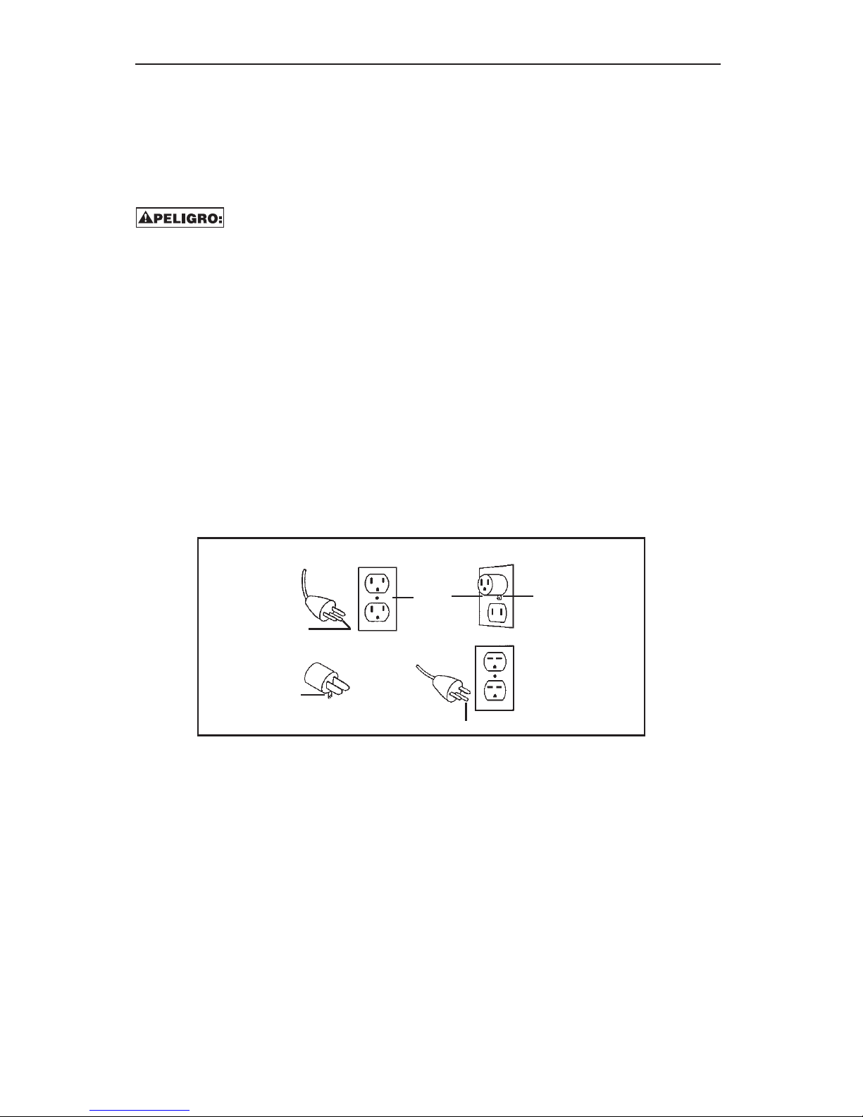
Este producto se envía para usarse en un circuito de 120 voltios nominales, y tiene un enchufe a
tierra que se ve como el que aparece en el dibujo A. Puede usarse un adaptador provisorio como
el que se ilustra en los dibujos B y C para conectar este enchufe en un receptáculo bipolar como
se muestra en el dibujo B, si no se cuenta con un receptáculo debidamente conectado a tierra.
Debe usarse el adaptador provisorio solamente hasta que un electricista capacitado pueda instalar
un receptáculo debidamente conectado a tierra (dibujo A). La oreja rígida de color verde o similar
que se extiende desde el adaptador debe conectarse a tierra permanentemente como, por
ejemplo, a la tapa de una caja de receptáculo debidamente conectada a tierra. Siempre que se use
un adaptador, debe sostenerlo en su lugar un tornillo metálico.
El motor de este compresor tiene un protector de sobrecarga térmica en el devanado del motor. Si
el motor se sobrecalentara, el protector de sobrecarga apaga el motor. Cuando la temperatura
vuelve al nivel normal, el motor se pone en marcha automáticamente.
¡AVISO! No detenga el compresor tirando del enchufe. Use solamente el interruptor de apagado
Auto/Off, el cual funciona como válvula de alivio de presión del compresor. Si el compresor está
enchufado con el interruptor en la posición “Auto”, puede tener dificultades para volver a ponerse en
marcha contra la presión alta que podría causar una acumulación de calor excesiva y dañar el motor.
Válvula de seguridad:
Este compresor está equipado con una válvula de seguridad que está fija de tal modo que evite el
exceso de presión en los tanques de aire. Esta válvula está prefijada de fábrica en 140 PSI y no
funciona a menos que la presión del tanque llegue a esta presión. NO INTENTE AJUSTAR NI
ELIMINAR ESTE MECANISMO DE SEGURIDAD. TODO AJUSTE A ESTA VÁLVULA PODRÍA
CAUSAR LESIONES GRAVES. Si el dispositivo necesita servicio o mantenimiento, consulte a un
Centro de Servicio Autorizado de BOSTITCH.
15
Pata a tierra
Tornillo metálico
Pata a tierra
Medio de conexión
a tierra
Tapa de la caja
de receptáculo
conectada a
tierra
AB
C

INSTRUCCIONES DE CONEXIÓN ELÉCTRICA A TIERRA: (continuación)
CICLO DE TRABAJO:
Para asegurar la larga vida útil del compresor de aire BOSTITCH, no lo haga funcionar a más del
50% del ciclo de trabajo. Si este compresor bombea aire más del 50% de una hora, entonces la
capacidad del compresor es menor que la entrega de aire necesaria para la aplicación. Siempre
haga coincidir los requisitos de volumen de aire del aditamento o accesorio con el volumen de aire
que entrega el compresor.
¡Aviso!: BOSTITCH no recomienda el uso de cables de extensión con los compresores. El uso de
un cable de extensión puede ocasionar la pérdida de voltaje suministrado al compresor, lo cual
podría impedir la puesta en marcha del mismo. Para lograr un rendimiento óptimo, enchufe el
compresor directamente en un receptáculo y aumente la longitud de la línea de aire según sea
necesario.
Si debe usar un cable de extensión, use estas directrices:
Distancia necesaria Calibre recomendado
menos de 25 pies Calibre 12
25 — 50 pies Calibre 10
Mayor que 50 pies No se recomienda
16

CARACTERÍSTICAS DEL BOSTITCH CAP2045ST-OL
A. Interruptor de presión: El interruptor de
presión es el mecanismo de activación que se
usa para poner en marcha y detener el
compresor. Cuando se mueve el interruptor a la
posición “AUTO”, el motor y la bomba comprime
el aire hasta que la presión del tanque llega al
límite superior de la presión operativa fijada en la
fábrica. Cuando la presión del tanque baja de la
presión de “entrada” fijada en la fábrica, el
compresor nuevamente comienza
automáticamente a comprimir el aire.
B. Medidor de presión del tanque: El medidor de
presión del tanque indica la presión existente en
el tanque en PSI (lbs/pulg. cuad.).
C. Medidor de presión regulada: El medidor de presión regulada indica la cantidad de presión que
se permite entrar a las dos líneas de descarga (E) según la selección del regulador.
D. Perilla del regulador: La perilla de regulador se usa para ajustar la presión de aire que está
disponible en las dos líneas de descarga. La presión de aire de descarga aumenta al girar la
perilla hacia la derecha y disminuye al girarla hacia la izquierda.
E. Líneas de descarga: Este compresor está equipado con dos líneas de descarga. Estas líneas se
extienden desde el panel de control tipo 1/4” hembra NPT para permitir al usuario final conectar el
accesorio del tamaño adecuado para la aplicación.
F. Grifos de drenaje: Válvulas de giro o extracción que drenan la humedad de los tanques cuando
se abren.
G. Drenaje de aceite: Al quitar el tapón de la mirilla, el
aceite puede drenarse del cigüeñal del compresor. La
abertura es aguzada para que pueda colocarse un
recipiente pequeño bajo la abertura para recoger
limpiamente el aceite.
H. Llenado de aceite: Al poner aceite en la unidad, se
vierte dentro de esta abertura. La abertura está diseñada
para actuar como embudo para facilitar un llenado más
limpio.
I. Mirilla: Este tapón de drenaje de aceite es transparente
para que el usuario uede verificar rápida y fácilmente el
nivel de aceite antes del funcionamiento.
17
A
B
C
D
E
F
G
H
I

INSTRUCCIONES DE OPERACIÓN
Procedimientos previos a la puesta en marcha:
1. Inspeccione el compresor en busca de componentes dañados. No lo haga funcionar si el
compresor está dañado.
2. Revise el nivel de aceite en la bomba del compresor (Consulte la sección “Verificación del nivel
de aceite”).
3. Revise que los tanques se hayan drenado y que estén despejados de toda humedad y suciedad
(Consulte la sección “Drenaje del tanque”).
4. Compruebe que el filtro de aire esté firme en su sitio (Consulte la sección “Instalación del filtro
de aire”).
Procedimientos de puesta en marcha:
1. Revise que el interruptor de apagado Auto/Off esté en la posición apagada Off.
2. Compruebe que la presión de aire del tanque esté en 0 PSI.
3. Conecte la manguera de aire a la línea de descarga.
4. Enchufe la unidad en un receptáculo debidamente conectado a tierra.
5. Ponga el interruptor Auto/Off en Auto. El compresor pasará automáticamente por sus ciclos de
encendido y apagado para mantener la presión del tanque.
6. Ajuste el regulador de presión a la selección correcta de presión necesaria para la herramienta
neumática.
Procedimientos de apagado:
1. Ponga el interruptor Auto/Off en la posición apagada Off.
MANTENIMIENTO GENERAL
Servicio y mantenimiento:
Antes de dar servicio o mantenimiento al compresor, desconecte siempre todos los accesorios y
aditamentos de la unidad, además desconecte el compresor del tomacorriente. Al cambiar piezas,
solamente use repuestos genuinos BOSTITCH.
Verificación del nivel de aceite de la bomba — Uso de la mirilla:
1. Revise que el compresor esté apagado y sobre una superficie nivelada.
2. Observe el nivel de aceite a través de la mirilla que está en la base
del cigüeñal.
3. Si se ve aceite hasta la mitad de la mirilla, el nivel de aceite es aceptable.
Verificación del nivel de aceite de la bomba — Uso de la varilla medidora:
1. Revise que el compresor esté apagado y sobre una superficie nivelada.
2. Retire la varilla del orificio de llenado de aceite.
3. Limpie el aceite de la varilla.
4. Reinsértela totalmente dentro del orificio de llenado de aceite unos momentos.
5. Retire la varilla y observe el nivel de aceite, el cual no
debe estar más arriba de la marca “MAX” ni más bajo de la marca “MIN”.
18

MANTENIMIENTO GENERAL (continuación)
Cambio de aceite:
1. Revise que el compresor esté apagado.
2. Ponga un recipiente pequeño bajo el orificio de drenaje del aceite (una taza común sirve).
3. Quite la varilla.
4. Retire el tapón de drenaje de aceite y mirilla.
5. Deje que el aceite drene dentro del recipiente — inclinando el compresor hacia
el tapón de drenaje para facilitar la tarea.
6. Inserte el tapón de drenaje de aceite y mirilla dentro del orificio de drenaje.
7. Ponga 7.5 oz de aceite no detergente 30w en el cigüeñal.
8. Inserte la varilla medidora.
Drenaje de los tanques — Grifos de drenaje tipo extracción:
1. Revise que el compresor esté apagado.
2. Sosteniendo el mango, incline el compresor hacia los grifos de drenaje de tal modo que queden
en la parte inferior del tanque.
3. Tire de la cuerda para abrir las válvulas de drenaje.
4. Sostenga hasta que se haya eliminado toda la humedad.
5. Suelte cuando termine.
Drenaje de los tanques — Grifos de drenaje tipo giro:
1. Revise que el compresor esté apagado.
2. Sosteniendo el mango, incline el compresor hacia los grifos de drenaje de tal modo que queden
en la parte inferior del tanque.
3. Gire los grifos de drenaje para abrir la válvula.
4. Mantenga el compresor inclinado hasta que se haya eliminado toda la humedad.
Instalación del filtro de aire:
1. Retire el tapón de plástico del costado del cabezal de la bomba.
2. Desmonte el elemento del filtro de aire de la caja.
3. Atornille el filtro de aire dentro de la abertura roscada en el costado del cabezal de la bomba.
Verificación y limpieza del filtro de aire:
LAS ALETAS DE ENFRIAMIENTO, EL CABEZAL DE LA BOMBA Y LAS PIEZAS
CIRCUNDANTES SE CALIENTAN MUCHO. NO LOS TOQUE.
1. Revise que el compresor esté apagado.
2. Retire la tapa girando hacia la derecha.
3. Desmonte el elemento del filtro de la tapa.
4. Limpie la almohadilla del filtro con agua y jabón según se necesite. Si el filtro se obstruye o
se daña, cámbielo.
NUNCA LIMPIE EL FILTRO DE AIRE CON UN LÍQUIDO O SOLVENTE INFLAMABLE.
SE PUEDEN ACUMULAR VAPORES EXPLOSIVOS EN LOS TANQUES DE AIRE Y CAUSAR UNA
EXPLOSIÓN, PRODUCIENDO LESIONES GRAVES O FATALES.
5. Inserte el elemento del filtro en la tapa.
6. Ponga la tapa del filtro en la base del mismo y gire hacia la izquierda para instalarla.
UN CENTRO DE SERVICIO AUTORIZADO DE BOSTITCH DEBE REALIZAR TODO OTRO SERVICIO
19

GUÍA PARA SOLUCIONAR PROBLEMAS
NOTA: DESCONECTE DE LA RED ELÉCTRICA Y DRENE LA PRESIÓN DEL TANQUE ANTES DE HACER REPARACIONES O AJUSTES.
Problema Causa probable Corrección
La unidad no funciona La presión del tanque excede la presión de “entrada” La unidad se pone en marcha una vez que baje la presión bajo la presión de “entrada”.
El cable de extensión causa excesivo consumo de amperaje Revise las pautas para ver el calibre correcto del cable
(no se recomienda usar cables de extensión).
Se disparó un fusible o circuito Cambie el fusible o disyuntor
La unidad no está encendida o no está enchufada Revise el interruptor de presión y verifique que esté en la posición Auto.
Compruebe que la unidad esté enchufada.
No se sacó el tapón del filtro de aire Retire el tapón de aire e instale el filtro de aire.
Condiciones climáticas frías Ponga el compresor en un ambiente más cálido al menos 30 minutos
(generalmente temperaturas bajo cero) luego pruebe volver a ponerlo en marcha.
Fugas de aire en los conectores Conectores sueltos Apriete los conectores. Revise con agua jabonosa. NO APRIETE EN EXCESO.
Fuga de aire en el interruptor Válvula de retención obstruida Retire y limpie la válvula de retención
de presión
La unidad no acumula presión La aplicación exige un consumo excesivo de aire Reduzca la demanda del compresor
Cabezal suelto Apriete los pernos del cabezal
Empaquetadura rota Retire el cabezal y revise si la empaquetadura está rota o deformada. Cámbiela si
es necesario.
La unidad no acumula presión Válvulas desgastadas o rotas Retire el cabezal y cambie las válvulas.
Fuga de aire en el tanque o Soldadoras dañadas del tanque de aire
tanque de aire. NO TALADRE, SUELDE NI MODIFIQUE EL TANQUE DE AIRE DE NINGUNA
MANERA. LOS TANQUES DAÑADOS O MODIFICADOS PUEDEN ROMPERSE. CAMBIE EL
TANQUE INMEDIATAMENTE.
20
Table of contents
Languages:


