Bredal SG500 Operation manual


2
EU Declaration of Compliance
(Directive 89/392/EEA, Annex II, supl. A)
Manufacturer: BREDAL A/S Nimvej 1, DK 7120 Vejle Ø
Hereby states that
BREDAL Type Serial number
Only for Teejet500 control
Cal. figure _____________________________
App. Rate cm3/impulse______________________
Impulses/100 meters _______________________
Computer no._____________________________
Is manufactured in compliance with the machinery directive
(Directive 89/392/EEA) with the latest amendments and national provisions
Bredal DK-7120 Vejle Ø 10th January 2013

3
Contents:
Start Page
Attachment ..........................................................................................................4
Mounting of computer and speed sensor.............................................................4
Calibrating of speed sensor……………………………………………………..4
Safety General ..................................................................................................................5
Road safety............................................................................................................5
Operation manually
Start /stop spreading..............................................................................................6
Adjustment of application.....................................................................................6
Adjustment of working width ...............................................................................6
Operation via computer
Overview...............................................................................................................7
Encode application................................................................................................7
Operation...............................................................................................................8
Registration of applied amount .............................................................................9
Alarms........................................................................................................... 10-11
Emptying.............................................................................................................12
Settings.......................................................................................................... 13-14
Speed sensor calibration......................................................................................14
Test......................................................................................................................15
Spreading salt
Downchute position.............................................................................................16
Height of discs.....................................................................................................16
Correction of spread pattern................................................................................16
Spreading of various materials
Fertilizer ..............................................................................................................17
Sand.....................................................................................................................17
Lime ....................................................................................................................17
Topdressing.........................................................................................................17
Maintenance
General ................................................................................................................18
Lubrication ..........................................................................................................18
After the season ..................................................................................................18
Technical data
Measures and weight...........................................................................................19

4
Attachment.
The spreader must be parallel to the ground or slightly inclined towards the tractor.
The height from the ground to the spread discs must be between 35 and 40 cm..
Hydraulic hoses must be coupled to the tractor and the oil flow set to approx. 25 to 30 ltr/minute.
Lights must be connected to the tractor and then make sure that lights are working properly before
bringing the spreader in operation.
Mounting of computer and speed sensor. (only SGS versions)
The Computer must be mounted in a way so the operation of it goes easy and smoothly, use the
bracket in the computer kit in order to get the best possible mounting. Most tractors do have a 3-leg
power supply connector which fits the power connector coming from the spreader. If the tractor
doesn’t have the 3-leg power supply it has to be established by eventually buying a power supply
kit from BREDAL. Do not in any case cut of the power connecter from the TeeJet 500 computer to
attach to the power supply direct, all warranty claims on the computer will be lost.
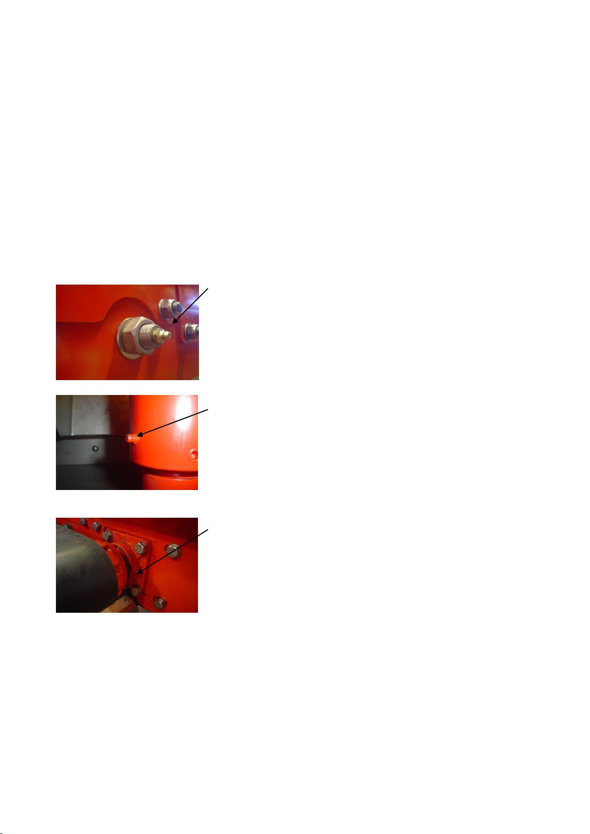
In order to get a speed input there are 2 ways.
Either there is a 7-pin plug in the tractor where the speed input can be taken by the use of a cable
(see below).
The other alternative is mounting a sensor on the 4-wheel drive shaft.
It´s important that the distance between sensor and magnet is maximum 4 mm.
Inductive sensor for speed. Cable from computer to speed sensor.
Calibrating of speed sensor.
Measure up a distance of 100 meters and drive to the start position..
Push the button menu, move the cursor with the arrows to encode, then enter, move the cursor to
speed sensor and push enter. Choose between radar and wheel sensor with the soft key buttons
under the screen, push drive 100 meter, drive 100 meter ahead, and enter to store the counted
number of impulses.
There should be a minimum of 300 to 400 impulses per 100 meters.
It´s possible to tap in the impulses if known.

5
Safety in general.
It´s important that safety precautions have been taken in order to avoid accidents with personnel and
items.
Follow the directions below:
-Do not stay in the working/spreading area when spreader is in operation.
-Do not stand on the spreader when in operation
-Do not stay on the spreader during road transport
-Avoid loading items that might be the cause of injuries when spread out.
-Guards over spread discs and the safety rails shall always be mounted when spreader is
operated.
-When maintenance work has been done on the spreader, be sure that the spreader is
sufficiently supported. Do never work on a raised spreader.
-When spreader is attached to the tractor, be careful not to stay between tractor and spreader.
-The pins for the 3-point linkage must be in the right sizes and locked by safety rings.
-Make sure that the lower link arms and the top linkage are as close to parallel with each
other as possible. A steep angled top linkage may overload the attachment points on tractor
and spreader.
Road safety.
Make sure that the traffic lights are undamaged, in working condition and are connected to the plug
on the tractor when driving on public roads. Remember to clean the lights every time you have been
spreading.

6
Start /stop spreading (SG).
Application and spreading discs are engaged and disengaged from the operation valves on the
tractor.
Adjustment of application (SG).
The application is set at the rear gates and the 2 valves at the front of the spreader.
When spreading salt the rear gate opening is set between 25 and 50 on the scale. When spreading
small amounts it can be necessary to minimize the rear gate opening.
The spreader doesn’t adjust the application automatically when the driving speed is changed, so it´s
important that a constant speed is held to obtain a consistent application.
The rear gate is set between scale 25 to 50 when
spreading salt.
When spreading vacuum salt the rear gate setting
shouldn’t be less than 30.
When spreading other materials the rear gate
opening is chosen depending on application and the
spreading width.
When the rear gates are set, then the floor belt speed
can be chosen on the 2 manual valves at the front of
the spreader.
One valve adjusts the speed on the floor belt and the
second valve adjusts the speed of the floor belt and
the speed of the spreading discs at the same.
The belt speed is chosen to comply with the forward
speed.
Adjustment of working width. (SG).
When application rate is set, the spreading width can be adjusted.
This is done on the second valve at the front of the spreader. One of the 2 valves is adjusting both
the floor belt speed and the spreading disc speed.
If the relation between application and working width is wrong, then change the rear gate opening
or the floor belt speed.
7
Overview.
Encode application.
The application is encoded in gram/m2 remember to encode the correct specific density of the
material to be spread for the correct application..
Press menu, move cursor to appl/setting and enter, move cursor to gram/m2 and enter. The figure
can be changed with the arrows, then enter to save the application or esc to go back to the previous
menu without saving.
The specific density is encoded in the same way.
BREDAL can supply a density kit for finding the exact specific density.
Then the rear gate setting must be encoded. First set the rear gates, then encode the set value in the
computer under menu and scale position.
When spreading salt a rear gate opening between 40 and 60 will be appropriate
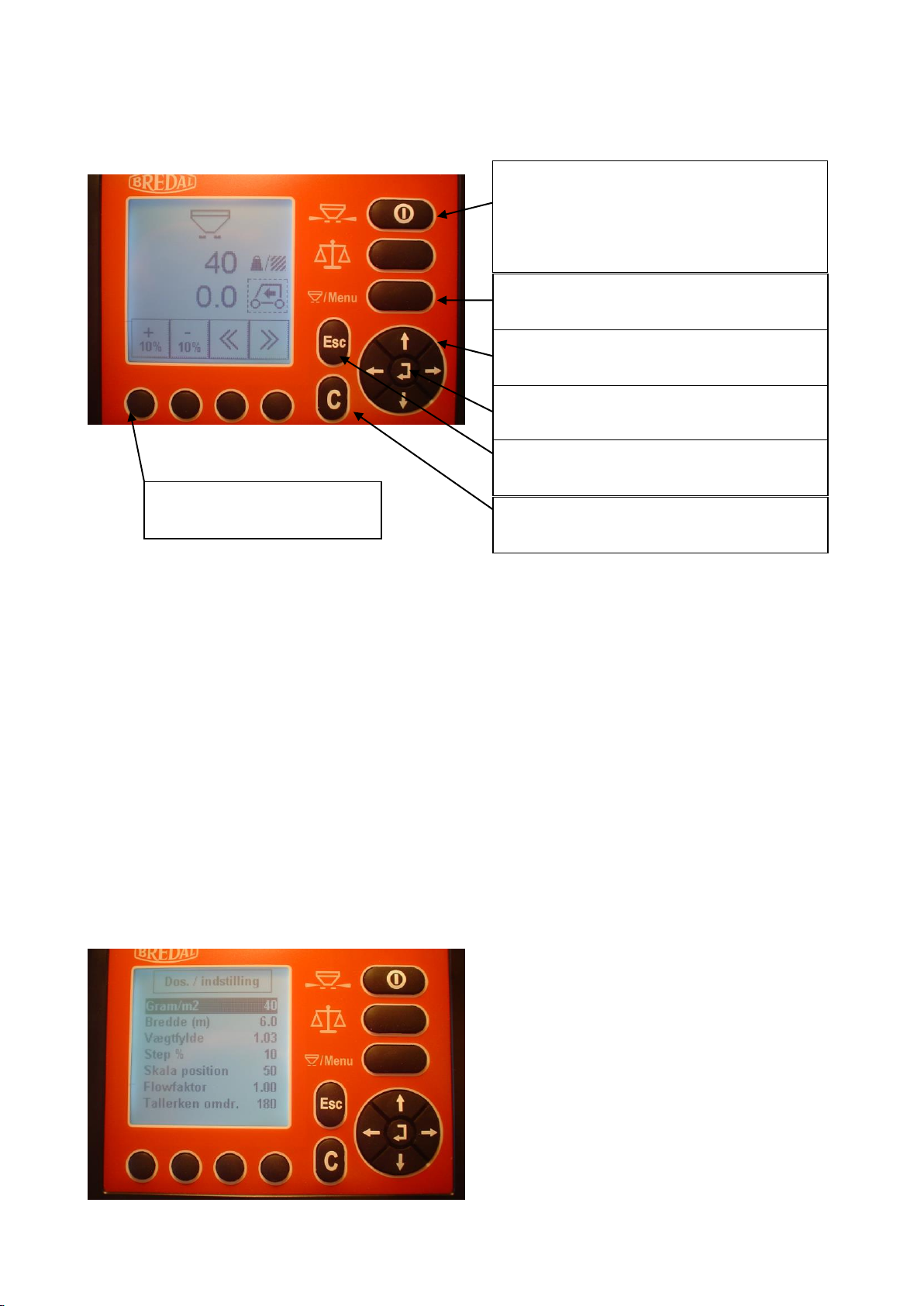
Application menu.
Before spreading encode the specific density in
gram/m2, working width, specific density and
scale position.
Menu, change between menu and
operation mode.
Arrows for moving the cursor or
changing value.
Enter, to accept the marked area.
C, to delete values and alarms.
On /off button, switch the computer on
by pressing this button and hold the
button down to switch the computer off.
Start /stop, spreading.
Esc, to step back without saving data.
To activate the symbols on
the screen.

8
Operation.
Operation 1.
Start /stop spreading by pressing start /stop.
Remember to engage oil flow to the spreader.
When spreading is engaged two “elongated
triangles” are shown.
The current application.
Change of application in percentage.
Operation 2.
When symbol ”m” is shown it´s possible to
change the working width in steps of +/- 1m
The current working width
By pressing the round buttons it´s possible to
switch between different pages.
Operation 3.
The arrows indicate that the floor belt speed is
changing.
The current application is changed by - 20% %
Forward speed.

9
Registration of applied amount.
There are 10 counters at disposal in the computer. The values in these counters can be deleted.
The main counter can´t be deleted.
To get to the counter press menu, move cursor
to counters and press enter.
Then move cursor to counter to be chosen and
click enter.
When a counter is chosen, the spread amount,
area and used time is shown.
Choose counter to delete the values and start a
new task.
If the values in the counter aren´t deleted
further registrations will be added.
The active counter is shown in the operation
menu when spreading.
.
A printer can be linked to the computer, so the
values in the counters can be printed out with
name and date on the receipt.
It´s possible to print one counter at the time or
all 10 counters in one go.

10
Alarms.
The computer surveys different functions on the spreader, in case of error the alarm will go off.
Once the alarm is activated, you can’t operate the computer until this alarm is set off by pressing the
C button.
Alarm will show if the floor belt doesn’t obtain
the correct speed.
The most common causes are:
No oil flow from tractor, open for oil flow.
Too small amount of oil from the tractor, either
increase the oil flow or reduce the forward
speed.
.
Alarm will show if the spread disc doesn’t
obtain the correct speed.
Most common causes:
No oil from the tractor, open for the oil flow.
The amount of oil is too low, increase
Alarm will show if there is a short circuit or if
power supply from the tractor is insufficient.
To set off the alarm, shut down the computer
and turn it on again.
Check all the cabling and connectors. If the
alarm still is activated call your Dealer.
The alarm can be set off by pressing the C
button, hereafter the computer can be operated
but there is no communication between tractor
and spreader.

11
> Alarms continued.
Alarm will show if menu is chosen when
spreading is going on.
Press C to set off the alarm, press start /stop to
stop spreading, then it´s possible to access the
menu.
Optional alarms.
It´s possible to set an alarm for almost empty
hopper.
Press menu, choose encode, alarms, kg rest.
Now the minimum amount can be encoded to
initiate the alarm.
Remember to set alarm by clicking On.
For the alarm to work properly it´s necessary to
encode how many kg is loaded, see explanation
below.
The kg /rest alarm is set in the following way.
Every time the hopper is filled up:
Press .
Press the button under the filling symbol.
Encode the amount in the hopper and press
enter. Press menu to return to operation mode.

12
Emptying.
If some material is left in the hopper it´s easy
to empty this out.
Press menu, choose emptying and press enter.
Emptying is started by pressing start /stop
Open eventually the rear gate.
Settings.
It´s possible to change the default settings on the computer.so it fits the best possible way for the
coming task.
Below different possibilities are shown.
It´s also possible to calibrate proportional valve and application rate.
Change of % step.
The step size in the operation mode can be set
as you wish.
Press menu, choose applic../setting, choose
step %, encode the chosen step size and press
enter.
Press menu to return to operation mode.
To change the step size of the working width.
Press menu, choose encode, choose working
width step, encode the new value and press
enter.
Press menu to return to operation mode.

13
> Settings continued.
The disc RPMs for the different working
widths are default encoded in the computer. If
the RPMs don’t fit the actual working width
it´s possible to encode an offset in %.
Press menu, choose encode, choose disc RPM
offset, encode the new offset and press enter.
Press menu to return to operation mode.
The proportional valve is already calibrated
from factory, but in some cases it´s necessary
to recalibrate it.
Press menu , choose encode, choose hydr.
calibration. Press enter to start calibration.
Remember to engage the oil flow from the
tractor.
The calibration will last for 1 minute, when
finished it will automatically return to the
menu encode.
Normally it´s not necessary to change the dose
calibration. If cm3/impulse is deleted by
mistake, the original figure can be encoded
again.. The dose calibration figure can be found
in the handbook.
Press menu, choose encode, choose dose.
calibration, encode the value and enter.
Press menu to return to operation mode

14
> Settings continued
If the screen doesn’t appear clear the brightness
contrast can be changed.
It´s possible to choose light on or off.
Press menu, choose system, choose contrast
/brightness and press enter.
Press menu to return to operation mode.
Speed sensor calibration.
The speed sensor must be calibrated to obtain
the right application and measuring the correct
area.
There must be minimum 300 to 400 pulses pr.
100 meter.
Press menu, choose encode, choose speed
sensor and press enter.
When impulses/100m is found, the figure can
be listed in the handbook
To calibrate the speed sensor, measure up a
distance of 100 meters and go to the start
position.
Choose between radar or wheel sensor.
Press button under symbol, and drive 100
meters (the impulses will appear) after the 100
meters press enter, the number of impulses is
shown, press enter to save and to go back to
encode menu.
.

15
Test.
In the menu test it´s possible to check the
different in- and outputs.
Press menu, then system, choose test and press
enter.
In the menu test it´s possible to check the
sensors.
When a sensor is activated, it will show on the
screen and switch between hi and low.
Every time a sensor is activated it will count.
In the menu test p.valve it´s possible to check
the output for the proportional valve.
If 40% is encoded, the power supply will be
40% of maximum power for the proportional
valve.
Remember to engage the oil flow from the
tractor.

16
Spreading salt.
Downchute position.
When spreading salt the downchutes must be
on scale 4. Remember to set both downchutes.
Height of discs.
When spreading salt there must be a distance of
40 cm from the ground.
Correction of spreading pattern.
It´s possible to change the spreading pattern by adjustment of downchutes and disc speed.
When the spread pattern is too wide or too narrow, the disc speed has to be changed so the correct
working width is obtained.
If the spreader is spreading on the correct width but the distribution of the spread material is wrong,
for example:
If there is too little amount behind the spreader and too much at the sides, it´s possible to correct
this by moving the downchutes one or two scales down
If the original setting on the downchute was 4, move it to scale 2 or 3.
If there is too much behind the spreader and too little at the sides, then move the downchutes one or
two scales up.

17
Spreading of various materials.
Fertilizer.
The biggest working width with fertilizer is 10 meters.
The downchute setting must be on scale 1 and the disc speed on 500 rpm.
These settings are valid from 2 to 10 meters of working width, in some cases the discs speed can be
reduced to 200 to 300 RPM on 2, 3 and 4 meters of working width.
Sand.
The spreader can be used for sand. The biggest working width is 6 to 10 meters depending of the
type of sand.
The downchute setting must be on scale 4 and the disc speed between 500 and 600 RPM and a rear
gate opening between 60 to 80.
Normally a ”big” opening of the rear gates is preferred by spreading of sand because of lumps. But
in some cases the rear gate opening has to be reduced because of sand breaking off in “lumps” and
causing a “jumping” spreading pattern.
Lime.
The biggest working width with lime is 6 meter.
The downchute setting must be on scale 4, 500 rpm´s on the spread discs and rear gate opening
between 80 to 100.
Topdressing.
The biggest working width will be 4 to 6 meters.
The downchutes must be set to scale 4 and the disc speed must be from 200 to 400 rpm and the rear
gates on scale between 60 and 80.
* Please consider that topdressing may cause an extensive wear on the spread vanes, so if possible
spread as narrow as possible with as less RPM on spreading discs as possible.
18
General maintenance.
It´s important to keep the spreader in top condition in order to prevent failures in the season.
In proper time before the spreading season the spreader has to be checked and worn out parts must
be replaced.
If the spreader is equipped with a computer, the computer must be stored warm and dry.
All electrical connections must be cleaned and sprayed with proper sprays for electrical
connections.
After every run the spreader must be cleaned.
Lubrication.
Guide rollers must be greased weekly.
The guide rollers are positioned in the middle of the carrying frame
on the left and right side.
The Pipes for spreading discs must be greased weekly.
The flanged bearings at the rear roller must be greased every second
week.
There is a bearing at each side of the roller.
After the season.
After the season a thorough wash is necessary.
Damaged paint must be repaired and finally the spreader must be oiled with appopriate oil.
Be careful not to expose rubber parts to oil.
The spreader must also be checked for further damages and worn out parts, the worn out parts must
be replaced by original parts in order to assure the right spreading performance.
If the spreader is equipped with computer, then store the computer dry and warm.

19
Measures and weight.
SG/SGS-1500
SG/SGS-1000
SG/SGS-500
Loading height
1430mm
1300mm
1125mm
Loading width
2000mm
1750mm
1400mm
Hopper length
1520mm
1200mm
1000mm
Total length
2035mm
2030mm
1970mm
Total width
2000mm
1770mm
1770mm
Total height
1430mm
1300mm
1120mm
Weight w/o extra load
445kg
420kg
400kg
This manual suits for next models
5
Table of contents


