Tribe EZ-Pilot Farmall 75C User manual

Version 5.00
Revision A
November 2013
Part number 78100-49-RS-E05
*78100-49-RS-E05*
INSTALLATION INSTRUCTIONS
Trimble® EZ-Pilot® Steering System
CaseIH Tractors Farmall 75C
Farmall 85C
Farmall 95C
Farmall 105C
New Holland Tractors T4.75
T4.85
T4.95
T4.105
T5.95
T5.105
T5.115

EZ-PILOT STEERING SYSTEM INSTALLATION INSTRUCTIONS 2
LEGAL NOTICES
Contact Information
Trimble Agriculture Division
10368 Westmoor Drive
Suite #100
Westminster, CO 80021
USA
www.trimble.com
©2012-2013, Trimble Navigation Limited. All rights reserved. Trimble,
the Globe & Triangle logo, EZ-Pilot, and FmX are trademarks of Trimble
Navigation Limited, registered in the United States and in other
countries. CFX-750 and Field-IQ are trademarks of Trimble Navigation
Limited.
Developed under a License of the European Union and the European
Space Agency. All other trademarks are the property of their respective
owners.
Release Notice
This is the November 2013 release (Revision A) of the EZ-Pilot Steering
System Installation Instructions, part number 78100-49-RS-E05.
Official Language
THE OFFICIAL LANGUAGE OF THESE TERMS AND CONDITIONS IS
ENGLISH. IN THE EVENT OF A CONFLICT BETWEEN ENGLISH AND
OTHER LANGUAGE VERSIONS, THE ENGLISH LANGUAGE SHALL
CONTROL.
Limited Warranty Terms and Conditions
Product Limited Warranty
Subject to the terms and conditions set forth herein, Trimble
Navigation Limited (“Trimble”) warrants that this product and its
internal components (the “Product”) shall be free from defects in
materials and workmanship and will substantially conform to Trimble’s
applicable published specifications for the Product for a period of one
(1) year, starting from the earlier of (i) the date of installation, or (ii) six
(6) months from the date of original Product shipment from Trimble.
Product Software
Product software, whether built into hardware circuitry as firmware,
provided as a standalone computer software product, embedded in
flash memory, or stored on magnetic or other media, is licensed and
not sold. If accompanied by a separate end user license agreement,
use of any such software will be subject to the terms of such end user
license agreement (including any differing limited warranty terms,
exclusions and limitations), which shall control over the terms and
conditions set forth in this limited warranty).
Software Updates
During the limited warranty period you will be entitled to receive such
Fix Updates and Minor Updates to the Product software that Trimble
releases and makes commercially available and for which it does not
charge separately, subject to the procedures for delivery to purchasers
of Trimble products generally. If you have purchased the Product from
an authorized Trimble distributor rather than from Trimble directly,
Trimble may, at its option, forward the software Fix Update or Minor
Update to the Trimble distributor for final distribution to you. Major
Upgrades, new products, or substantially new software releases, as
identified by Trimble are expressly excluded from this update process
and limited warranty. Receipt of software updates shall not serve to
extend the limited warranty period.
For purposes of this warranty the following definitions shall apply: (1)
“Fix Update” means an error correction or other update created to fix
a previous software version that does not substantially conform to its
published specifications; (2) “Minor Update” occurs when
enhancements are made to current features in a software program;
and (3) “Major Upgrade” occurs when significant new features are
added to software, or when a new product containing new features
replaces the further development of a current product line. Trimble
reserves the right to determine, in its sole discretion, what constitutes
a significant new feature and Major Upgrade.
Warranty Remedies
If the Trimble Product fails during the warranty period for reasons
covered by this Limited Warranty and you notify Trimble of such failure
during the warranty period, Trimble at its option will repair OR replace
the nonconforming Product, OR refund the purchase price paid by you
for the Product, upon your return of the Product to Trimble in
accordance with Trimble's standard return material authorization
procedures.
How to Obtain Warranty Service
To obtain warranty service for the Product, please contact your Trimble
dealer. Alternatively, you may contact Trimble to request warranty
service at +1-408-481-6940 (24 hours a day) or e-mail your request to
[email protected]om. Please be prepared to provide:
– your name, address, and telephone numbers
– proof of purchase
– this Trimble warranty card
– a description of the nonconforming Product including the model
number
– an explanation of the problem.
The customer service representative may need additional information
from you depending on the nature of the problem.
Warranty Exclusions and Disclaimer
This Product limited warranty shall only apply in the event and to the
extent that (i) the Product is properly and correctly installed,
configured, interfaced, maintained, stored, and operated in
accordance with Trimble's applicable operator's manual and
specifications, and; (ii) the Product is not modified or misused. This
Product limited warranty shall not apply to, and Trimble shall not be
responsible for defects or performance problems resulting from (i) the
combination or utilization of the Product with hardware or software
products, information, data, systems, interfaces or devices not made,
supplied or specified by Trimble; (ii) the operation of the Product
under any specification other than, or in addition to, Trimble's
standard specifications for its products; (iii) the unauthorized,
installation, modification, or use of the Product; (iv) damage caused
by: accident, lightning or other electrical discharge, fresh or salt water
immersion or spray; or exposure to environmental conditions for
which the Product is not intended; or (v) normal wear and tear on
consumable parts (e.g., batteries). Trimble does not warrant or
guarantee the results obtained through the use of the Product. NOTICE
REGARDING PRODUCTS EQUIPPED WITH GPS TECHNOLOGY: TRIMBLE
IS NOT RESPONSIBLE FOR THE OPERATION OR FAILURE OF OPERATION
OF GPS SATELLITES OR THE AVAILABILITY OF GPS SATELLITE SIGNALS.
THE FOREGOING LIMITED WARRANTY TERMS STATE TRIMBLE'S ENTIRE
LIABILITY, AND YOUR EXCLUSIVE REMEDIES, RELATING TO
PERFORMANCE OF THE TRIMBLE PRODUCT. EXCEPT AS OTHERWISE
EXPRESSLY PROVIDED HEREIN, THE PRODUCT AND ACCOMPANYING
DOCUMENTATION AND MATERIALS ARE PROVIDED “AS-IS” AND
WITHOUT EXPRESS OR IMPLIED WARRANTY OF ANY KIND, BY EITHER
TRIMBLE OR ANYONE WHO HAS BEEN INVOLVED IN ITS CREATION,
PRODUCTION, INSTALLATION, OR DISTRIBUTION, INCLUDING, BUT
NOT LIMITED TO, THE IMPLIED WARRANTIES OF MERCHANTABILITY
AND FITNESS FOR A PARTICULAR PURPOSE, TITLE, AND
NONINFRINGEMENT. THE STATED EXPRESS WARRANTIES ARE IN LIEU
OF ALL OBLIGATIONS OR LIABILITIES ON THE PART OF TRIMBLE
ARISING OUT OF, OR IN CONNECTION WITH, ANY PRODUCT.
SOME STATES AND JURISDICTIONS DO NOT ALLOW LIMITATIONS ON
DURATION OR THE EXCLUSION OF AN IMPLIED WARRANTY, SO THE
ABOVE LIMITATION MAY NOT APPLY TO YOU.
Limitation of Liability
TRIMBLE'S ENTIRE LIABILITY UNDER ANY PROVISION HEREIN SHALL BE
LIMITED TO THE AMOUNT PAID BY YOU FOR THE PRODUCT. TO THE
MAXIMUM EXTENT PERMITTED BY APPLICABLE LAW, IN NO EVENT
SHALL TRIMBLE OR ITS SUPPLIERS BE LIABLE FOR ANY INDIRECT,
SPECIAL, INCIDENTAL OR CONSEQUENTIAL DAMAGE WHATSOEVER
UNDER ANY CIRCUMSTANCE OR LEGAL THEORY RELATING IN ANYWAY
TO THE PRODUCTS, SOFTWARE AND ACCOMPANYING
DOCUMENTATION AND MATERIALS, (INCLUDING, WITHOUT
LIMITATION, DAMAGES FOR LOSS OF BUSINESS PROFITS, BUSINESS
INTERRUPTION, LOSS OF DATA, OR ANY OTHER PECUNIARY LOSS),
REGARDLESS OF WHETHER TRIMBLE HAS BEEN ADVISED OF THE
POSSIBILITY OF ANY SUCH LOSS AND REGARDLESS OF THE COURSE OF
DEALING WHICH DEVELOPS OR HAS DEVELOPED BETWEEN YOU AND
TRIMBLE. BECAUSE SOME STATES AND JURISDICTIONS DO NOT ALLOW
THE EXCLUSION OR LIMITATION OF LIABILITY FOR CONSEQUENTIAL OR
INCIDENTAL DAMAGES, THE ABOVE LIMITATION MAY NOT APPLY TO
YOU.
PLEASE NOTE: THE ABOVE TRIMBLE LIMITED WARRANTY
PROVISIONS WILL NOT APPLY TO PRODUCTS PURCHASED IN THOSE
JURISDICTIONS, SUCH AS COUNTRIES OF THE EUROPEAN ECONOMIC
COMMUNITY, IN WHICH PRODUCT WARRANTIES ARE OBTAINED
FROM THE LOCAL DISTRIBUTOR. IN SUCH CASE, PLEASE CONTACT
YOUR TRIMBLE DEALER FOR APPLICABLE WARRANTY INFORMATION.
Registration
To receive information regarding updates and new products, please
contact your local dealer or visit the Trimble website at
www.trimble.com/register. Upon registration you may select the
newsletter, upgrade or new product information you desire.
Notice to Our European Union Customers
For product recycling instructions and more information, please go to:
www.trimble.com/ev.shtml
Recycling in Europe:
To recycle Trimble WEEE, call +31 497 53 2430, and ask
for the “WEEE Associate”, or
mail a request for recycling instructions to:
Trimble Europe BV
c/o Menlo Worldwide Logistics
Meerheide 45
5521 DZ Eersel, NL

EZ-PILOT STEERING SYSTEM INSTALLATION INSTRUCTIONS 3
Safety Information
Always follow the instructions that accompany a Warning or Caution. The information they provide is
intended to minimize the risk of personal injury and/or damage to property. In particular, observe
safety instructions that are presented in the following format:
CWARNING – This alert warns of a potential hazard, which, if not avoided, can cause severe
injury.
CCAUTION – This alert warns of a hazard or unsafe practice which, if not avoided, can cause
injury or damage.
Note – An absence of specific alerts does not mean that there are no safety risks involved.
Warnings
CWARNING – When you are working on the vehicle’s hydraulic systems, vehicle attachments
that are suspended can drop. If you are working around the vehicle, you could suffer serious
injury if an attachment dropped on you. To avoid this risk, lower all vehicle attachments to the
ground before you begin work.
CWARNING – If someone else attempts to drive the vehicle while you are working on or under
it, you can suffer serious or fatal injuries. To avoid this possibility, install a lockout box on the
battery terminal to prevent the battery from being reconnected, remove the key from the
vehicle’s ignition switch, and attach a “Do not operate” tag in the cab.
CWARNING – Agricultural chemicals can pose serious health risks. If the vehicle has been used
to apply agricultural chemicals, steam clean the vehicle to remove any chemical residue from
the areas of the vehicle where you will be working.
CWARNING – Vehicle cabs can be quite high in the air. To avoid potentially serious injury
through falling from this height, always use the steps and handrails, and face the vehicle, when
you enter or exit it.Add the following warnings.
CWARNING – THE EZ-PILOT ASSISTED STEERING SYSTEM IS SOLELY INTENDED FOR
AGRICULTURAL USE IN AN OPEN FIELD ENVIRONMENT WITH AGRICULTURAL VEHICLES
APPROVED BY THE MANUFACTURER FOR USE WITH THE EZ-PILOT SYSTEM, AND SHOULD NOT
BE USED WITH ANY OTHER TYPE OF VEHICLE OR FOR ANY OTHER PURPOSE.
Contact your local EZ-Pilot® system reseller or check www.trimble.com to confirm that the
EZ-Pilot system has been tested and approved by the manufacturer for use with your vehicle
make and model. The EZ-Pilot system should not be installed on a vehicle not approved by the
manufacturer for such use. Installation of the EZ-Pilot system on an unapproved vehicle will
invalidate the product warranty.
EZ-PILOT STEERING SYSTEM INSTALLATION INSTRUCTIONS
Safety Information
4
Cautions
CCAUTION – When the vehicle has been running, parts of the vehicle, including the engine and
exhaust, can become extremely hot and can cause serious burns. To avoid burns, allow hot
machine parts to cool before you begin working on them.
CCAUTION – The system installation may bring you into contact with chemical substances, such
as oil, which can cause poisoning. Wash your hands thoroughly after you finish working on the
system.
CCAUTION – Battery posts, terminals, and related accessories contain lead and lead
compounds, which can cause serious illness. To avoid ingesting lead, wash your hands
thoroughly after touching the battery.
CCAUTION – Always wear protective equipment appropriate to the job conditions and the
nature of the vehicle. This includes wearing protective glasses when you use pressurized air or
water, and correct protective welder’s clothing when welding. Avoid wearing loose clothing or
jewelry that can catch on machine parts or tools.
CCAUTION – Parts of the vehicle may be under pressure. To avoid injury from pressurized parts,
relieve all pressure in oil, air, and water systems before you disconnect any lines, fittings, or
related items. To avoid being sprayed by pressurized liquids, hold a rag over fill caps, breathers,
or hose connections when you remove them. Do not use your bare hands to check for
hydraulic leaks. Use a board or cardboard instead.
CCAUTION – Do not direct pressurized water at:
- electronic or electrical components or connectors
- bearings
- hydraulic seals
- fuel injection pumps
- any other sensitive parts or components
Set the hose pressure as low as practicable, and spray at a 45° to 90° angle. Keep the nozzle of
the power washer away from the machine at the distance recommended by the manufacturer.
CCAUTION – To avoid malfunctions, or damage to cables:
- route cables away from areas where they may be pinched or rubbed.
- do not alter cable lengths and connections. If you must alter the length of the power cable do
not remove the fuse or fuse holder from the cable.

EZ-PILOT STEERING SYSTEM INSTALLATION INSTRUCTIONS 5
Contents
Safety Information . . . . . . . . . . . . . . . . . . . . . . . . . . . . . . . . . . . . . 3
Warnings . . . . . . . . . . . . . . . . . . . . . . . . . . . . . . . . . . . . . . . . . . . . . . . . . . . . . 3
Cautions . . . . . . . . . . . . . . . . . . . . . . . . . . . . . . . . . . . . . . . . . . . . . . . . . . . . . 4
1 Introduction. . . . . . . . . . . . . . . . . . . . . . . . . . . . . . . . . . . . . . . . . 7
Technical assistance . . . . . . . . . . . . . . . . . . . . . . . . . . . . . . . . . . . . . . . . . . . . . . . 7
Required components . . . . . . . . . . . . . . . . . . . . . . . . . . . . . . . . . . . . . . . . . . . . . . 8
Hardware organization . . . . . . . . . . . . . . . . . . . . . . . . . . . . . . . . . . . . . . . . . . . . . 9
2 EZ-Pilot System Installation . . . . . . . . . . . . . . . . . . . . . . . . . . . . . . . 10
Preparing the vehicle . . . . . . . . . . . . . . . . . . . . . . . . . . . . . . . . . . . . . . . . . . . . . .11
Removing the steering wheel . . . . . . . . . . . . . . . . . . . . . . . . . . . . . . . . . . . . . . . . . .11
Installing the anti-rotation bracket . . . . . . . . . . . . . . . . . . . . . . . . . . . . . . . . . . . . . . .22
Modifying the plastic cover . . . . . . . . . . . . . . . . . . . . . . . . . . . . . . . . . . . . . . . . . . .24
Reassembling the steering column . . . . . . . . . . . . . . . . . . . . . . . . . . . . . . . . . . . . . . .29
Assembling the SAM-200 EZ-Pilot drive motor . . . . . . . . . . . . . . . . . . . . . . . . . . . . . . . .32
Installing the SAM-200 EZ-Pilot drive motor. . . . . . . . . . . . . . . . . . . . . . . . . . . . . . . . . .33
Installing the Trimble steering wheel. . . . . . . . . . . . . . . . . . . . . . . . . . . . . . . . . . . . . .35
Removing the SAM-200 motor . . . . . . . . . . . . . . . . . . . . . . . . . . . . . . . . . . . . . . . . .41
Additional information . . . . . . . . . . . . . . . . . . . . . . . . . . . . . . . . . . . . . . . . . . . . .41
3 IMD-600 Unit Installation . . . . . . . . . . . . . . . . . . . . . . . . . . . . . . . . 42
Preparing the IMD-600 unit for installation . . . . . . . . . . . . . . . . . . . . . . . . . . . . . . . . . .43
Mounting the IMD-600 unit in the cab. . . . . . . . . . . . . . . . . . . . . . . . . . . . . . . . . . . . .44
4 Display Connections . . . . . . . . . . . . . . . . . . . . . . . . . . . . . . . . . . . 46
FmX integrated display . . . . . . . . . . . . . . . . . . . . . . . . . . . . . . . . . . . . . . . . . . . .47
CFX-750 display . . . . . . . . . . . . . . . . . . . . . . . . . . . . . . . . . . . . . . . . . . . . . . . .48
Connecting the EZ-Pilot system. . . . . . . . . . . . . . . . . . . . . . . . . . . . . . . . . . . . . . . . .49
Installing the emergency stop switch . . . . . . . . . . . . . . . . . . . . . . . . . . . . . . . . . . . . .55
CFX-750 and FmX displays: Installing the GNSS antenna and mounting plate . . . . . . . . . . . . . . . 57
CFX-750 and FmX displays: Installing the RTK radio antenna. . . . . . . . . . . . . . . . . . . . . . . . .60
5 Remote Engage . . . . . . . . . . . . . . . . . . . . . . . . . . . . . . . . . . . . . . 62
Installing the remote engage switch . . . . . . . . . . . . . . . . . . . . . . . . . . . . . . . . . . . . . .63
FmX integrated display . . . . . . . . . . . . . . . . . . . . . . . . . . . . . . . . . . . . . . . . . . .63
CFX-750 display . . . . . . . . . . . . . . . . . . . . . . . . . . . . . . . . . . . . . . . . . . . . . . .64
Setting up the CFX-750 display . . . . . . . . . . . . . . . . . . . . . . . . . . . . . . . . . . . . . . . . .68
Setting up the FmX integrated display . . . . . . . . . . . . . . . . . . . . . . . . . . . . . . . . . . . . . 69
6 Final Machine Check . . . . . . . . . . . . . . . . . . . . . . . . . . . . . . . . . . . 70
Performing the final machine check . . . . . . . . . . . . . . . . . . . . . . . . . . . . . . . . . . . . . .71
EZ-Pilot calibration tips . . . . . . . . . . . . . . . . . . . . . . . . . . . . . . . . . . . . . . . . . . . . .71
Front wheel steer tractors . . . . . . . . . . . . . . . . . . . . . . . . . . . . . . . . . . . . . . . . . . .72
Advanced parameters . . . . . . . . . . . . . . . . . . . . . . . . . . . . . . . . . . . . . . . . . . . . 72
Vehicle measurements . . . . . . . . . . . . . . . . . . . . . . . . . . . . . . . . . . . . . . . . . . . . .73


1
EZ-PILOT STEERING SYSTEM INSTALLATION INSTRUCTIONS 7
CHAPTER
Introduction 1
In this chapter:
Technical assistance
Required components
Hardware organization
This manual describes how to install the
Trimble® EZ-Pilot® steering system.
Even if you have used another Global Navigation
Satellite System (GNSS), such as the United
States’ Global Positioning System (GPS)
products before, Trimble recommends that you
spend some time reading this manual to learn
about the special features of this product. If you
are not familiar with GNSS, visit the Trimble
website (www.trimble.com) for an interactive
look at Trimble and GNSS.
Technical assistance
If you have a problem and cannot find the information you need in the product documentation,
contact Trimble technical support:
1. Log into http://agpartners.trimble.com.
2. Click the Feedback link at the right of the screen. A form appears.
3. Complete the form and then click Submit Feedback.

EZ-PILOT STEERING SYSTEM INSTALLATION INSTRUCTIONS
1– Introduction
8
Required components
EZ-Pilot platform kit components
Kits required Tools
EZ-Pilot platform kit: P/N 78100-49-RS
Trimble steering wheel kit: P/N 78200-00
Note – The Trimble steering wheel must be
purchased separately.
27 mm deep socket
T20 Torx screw driver
#2 Phillips screw driver
Offset ratcheting screw driver with T20 torx bit
Small thin-blade screw driver
Steering wheel puller
4 mm L-shaped stubby hex wrench
5 mm T-handle hex wrench
4 mm T-handle hex wrench
⅛'' drill bit
#1 step drill, ⅛'' - ½'' increments
#20 step drill, 9/16'' - 1'' increments
Component Component
cSteering shaft lower adapter gBracket, anti-rotation
dLock, telescopic extension hFlat washer, M8
ePin, anti-rotation, 75 mm iScrew, socket head cap, M5 x 0.8 x 12 mm
fSpacer, 5
/16" ID x ¾" OD x ⅞" long jScrew, socket head cap, M6 x 1.0 x 25 mm

EZ-PILOT STEERING SYSTEM INSTALLATION INSTRUCTIONS
1– Introduction
9
Hardware organization
Note:
the Trimble steering wheel.
The center cap and lock knob are included with
The Trimble steering wheel, P/N 78200-00,
must be purchased separately.
❶
❷
❸
❹
❺
❻
❼
❽

2
EZ-PILOT STEERING SYSTEM INSTALLATION INSTRUCTIONS 10
CHAPTER
EZ-Pilot System Installation 2
In this chapter:
Preparing the vehicle
Removing the steering wheel
Installing the anti-rotation bracket
Modifying the plastic cover
Reassembling the steering column
Assembling the SAM-200 EZ-Pilot drive
motor
Installing the SAM-200 EZ-Pilot drive motor
Installing the Trimble steering wheel
Removing the SAM-200 motor
Additional information
This chapter describes how to how to install the
anti-rotation bracket and drive motor for the
EZ-Pilot steering system.
CWARNING – To avoid potentially serious
personal injury or illness, and to prevent
damage to equipment, make sure that
you read and understand the Safety
Information chapter.
EZ-PILOT STEERING SYSTEM INSTALLATION INSTRUCTIONS
2 – EZ-Pilot System Installation
11
Preparing the vehicle
1. Park the vehicle on a hard, level surface.
2. Engage the park brake and then remove the ignition key.
3. On an articulated vehicle, install the articulation locks.
4. Remove all dirt and debris from the areas of the vehicle where the system is to be installed.
5. Open all kit boxes and lay all of the parts out on a clean workbench.
6. Check the contents of the boxes against the packing lists.
Note – The left and right sides of the vehicle are referenced while standing behind the vehicle, facing
the normal direction of travel.
Removing the steering wheel
CWARNING – To avoid potentially serious personal injury or illness, and to prevent damage to
equipment, make sure that you read and understand the Safety Information chapter.
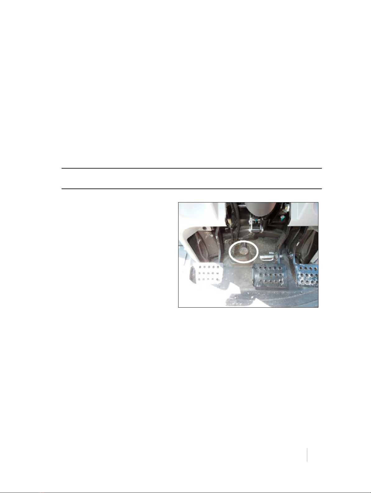
Step 1
Tilt the column fully down and then lock the
column into place.
Foot pedal tilt lever

EZ-PILOT STEERING SYSTEM INSTALLATION INSTRUCTIONS
2 – EZ-Pilot System Installation
12
Step 2
Remove the steering wheel center cap. Pull it
upwards by hand, or use a 1/8" flat blade
screwdriver to push it up.

EZ-PILOT STEERING SYSTEM INSTALLATION INSTRUCTIONS
2 – EZ-Pilot System Installation
13
Step 3
Machines are offered both with and without a
telescoping wheel. If equipped with a
telescopic wheel, use a 13 mm socket to
remove the hex nut. Remove the lock knob
and spacer underneath.
Step 4
Use a 27 mm deep socket, and an air or
electric impact tool to remove the large hex
nut.
Wheel with telescopic feature
Spacer
Wheel without telescopic feature

EZ-PILOT STEERING SYSTEM INSTALLATION INSTRUCTIONS
2 – EZ-Pilot System Installation
14
Step 5
Remove the steering wheel.
Example tool:
http://www.otctools.com, P/N 7403
www.oem-tools.com, P/N 27017
For machines equipped with a telescopic
wheel use the included 5
/16" ID x ¾" OD x ⅞"
long spacer to protect the threaded lock shaft
while pulling the wheel.
Non-telescopic steering columns
Use 6 mm x 1.0 x 65 mm bolts.
www.mcmaster.com,
P/N 91280A249
Telescopic steering columns
Use 6 mm x 1.0 x 100 mm bolts.
www.mcmaster.com, P/N 91280A358
Note – There are more images for this step on
the next page.
Telescopic steering column
OTC 7403 puller


EZ-PILOT STEERING SYSTEM INSTALLATION INSTRUCTIONS
2 – EZ-Pilot System Installation
16
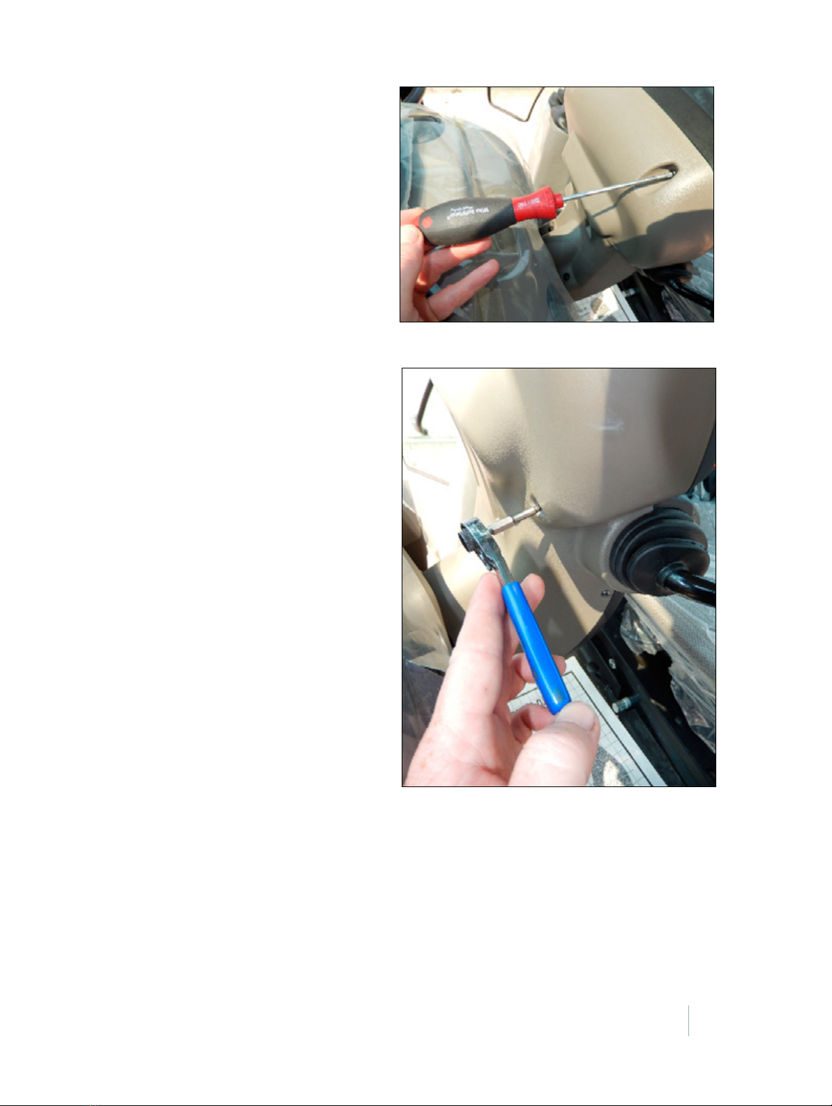
Step 6
Remove the eight screws that hold the plastic
cover in place:
• Four Torx screws are located on the back
around the instrument cluster. Use a T20
Torx screwdriver and offset ratcheting
screwdriver with T20 torx bit.
• Two Phillips head screws are on either side
just below the levers. Use a #2 Phillips
screwdriver.
• Two Phillips screws are at the lower front
near the bottom of the cover.
Example tools:
www.snapon.com
Part numbers: BTWOS, SDMTAS20
www.wihatools.com
Part numbers: 36254, 76855
Note – There are more images for this step on
page 17 and page 18.

EZ-PILOT STEERING SYSTEM INSTALLATION INSTRUCTIONS
2 – EZ-Pilot System Installation
17
x
EZ-PILOT STEERING SYSTEM INSTALLATION INSTRUCTIONS
2 – EZ-Pilot System Installation
18
y
T20 Torx screwdriver
Offset racheting screwdriver with T20 Torx bit
EZ-PILOT STEERING SYSTEM INSTALLATION INSTRUCTIONS
2 – EZ-Pilot System Installation
19
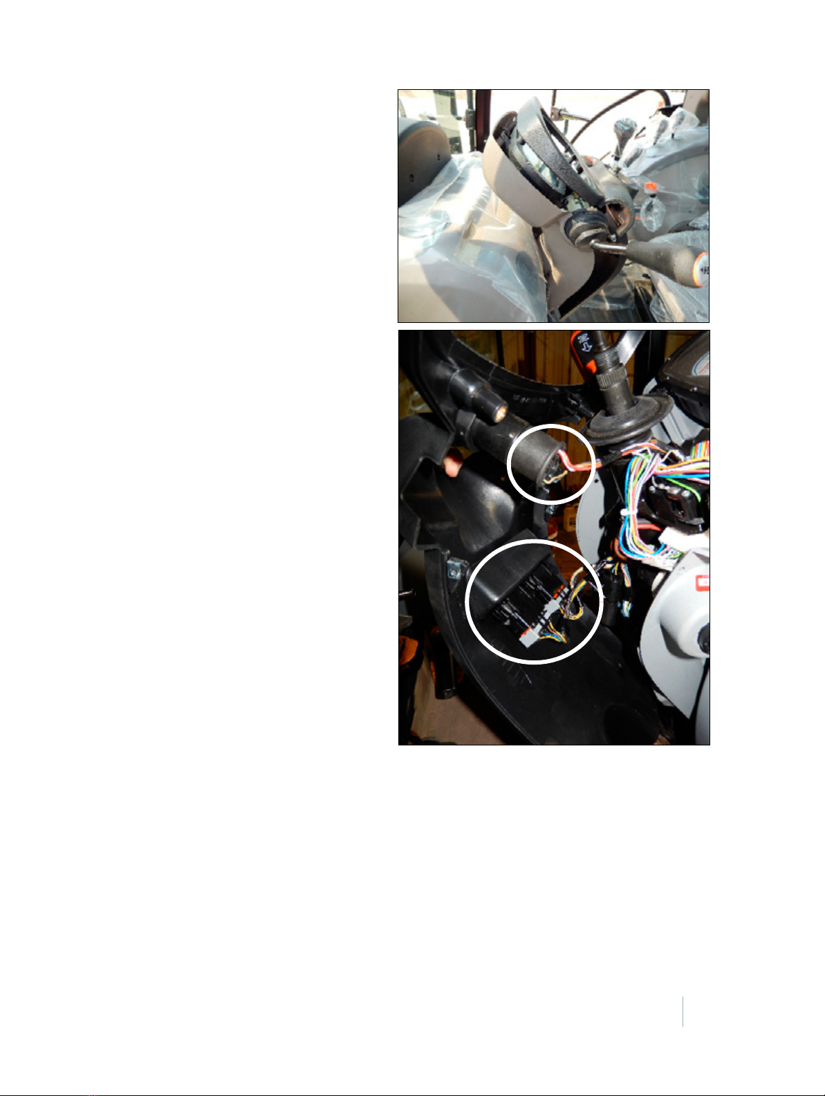
Step 7
Remove the cover and disconnect the wiring
harness from the switches. Pry the locking tabs
outward and then pull the connector out of
the socket.
Note – There are more images for this step on
the next page.
New Holland T5 series tractors

EZ-PILOT STEERING SYSTEM INSTALLATION INSTRUCTIONS
2 – EZ-Pilot System Installation
20
Locking tabs
New Holland T5 series tractors
Case IH Farmall C series tractors
This manual suits for next models
3
Table of contents


