C.P.Bourg BM-e User manual
OPERATOR
OPERATOR
MANUAL
MANUAL
Initial version: 11/08
Lastest revision: 02/10
9.134.030

Operator manual
Page 9 - 2 Initial version : 11/08
Lastest revision : -
Content of this documentation remains the exclusive property of C.P. Bourg SA and
it is only put at the user (including without limitation: Renter or Purchaser or their
employees) disposal within the exclusive scope of using and servicing the product.
Without C.P. Bourg SA prior agreement in writing, reproductions as well as changes
are prohibited.

Operator manual
Page 9 - 3 Initial version : 11/08
Lastest revision : 02/09
TABLE OF CONTENTS
1. IMPORTANT. . . . . . . . . . . . . . . . . . . . . . . . . . . . . . . . . . . . . . . . . . . . 5
2. INTRODUCTION. . . . . . . . . . . . . . . . . . . . . . . . . . . . . . . . . . . . . . . . . 6
2.1 Foreword . . . . . . . . . . . . . . . . . . . . . . . . . . . . . . . . . . . . . . . . . . . . . . . . . . . 6
3. BME . . . . . . . . . . . . . . . . . . . . . . . . . . . . . . . . . . . . . . . . . . . . . . . . . . 7
3.1 Warning Pictograms . . . . . . . . . . . . . . . . . . . . . . . . . . . . . . . . . . . . . . . . . . . 7
3.2 Warning pictograms location. . . . . . . . . . . . . . . . . . . . . . . . . . . . . . . . . . . . 10
3.3 BME description . . . . . . . . . . . . . . . . . . . . . . . . . . . . . . . . . . . . . . . . . . . . . 12
3.3.1 Technical characteristics ................................................................12
3.3.2 Stitching possibilities depending on paper width ............................15
3.3.3 Technical specifications ..................................................................16
3.3.4 Stitch and Fold offset possibilities ...................................................18
3.4 BM-e Process Description . . . . . . . . . . . . . . . . . . . . . . . . . . . . . . . . . . . . . 20
3.5 BME power ON . . . . . . . . . . . . . . . . . . . . . . . . . . . . . . . . . . . . . . . . . . . . . 21
3.6 Stitching head adjustment. . . . . . . . . . . . . . . . . . . . . . . . . . . . . . . . . . . . . . 22
3.6.1 Stitching heads mechanical unclutching ........................................22
3.6.2 Stitching wire length adjustment .....................................................23
3.6.3 Cassettes replacement with ISP heads...........................................23
3.6.4 Wire spool replacement (for Hohner heads) ..................................26
3.6.5 Wire jam in the stitching head ........................................................27
4. THE USER INTERFACE (UI) SCREENS. . . . . . . . . . . . . . . . . . . . . 28
5. SCREEN FUNCTIONS IN DETAIL . . . . . . . . . . . . . . . . . . . . . . . . . 29
5.1 U.I. screen options . . . . . . . . . . . . . . . . . . . . . . . . . . . . . . . . . . . . . . . . . . . 29
5.1.1 U.I. screen Operator's preferences ................................................30
5.1.2 Machines line configuration ..........................................................31
5.1.3 File menu ........................................................................................37
5.2 BST-e screen options . . . . . . . . . . . . . . . . . . . . . . . . . . . . . . . . . . . . . . . . . 38
5.3 BME screen options . . . . . . . . . . . . . . . . . . . . . . . . . . . . . . . . . . . . . . . . . . 39
5.3.1 Paper format and Stitcher parameters screen ...............................40
5.3.2 Folding parameter ...........................................................................42
5.3.3 Trimming parameter .......................................................................43
5.3.4 Output conveyor parameter ............................................................44
5.3.5 Productivity and Summary parameter ............................................45
5.3.6 File menu parameter ....................................................................46
5.3.7 Preferences Menu .........................................................................52
5.3.8 Warning screen and error messages ...........................................54
5.3.9 STOP button .................................................................................55
5.3.10 Start button .................................................................................55
5.3.11 Pause button .................................................................................55
5.3.12 Purge button .................................................................................55
5.3.13 Counter of set (configuration BST-e / BM-e) ................................56
5.3.14 U.I. version and update history .....................................................58
5.4 RUN screen options . . . . . . . . . . . . . . . . . . . . . . . . . . . . . . . . . . . . . . . . . . 59
5.4.1 BST-e adjustments in RUN mode ...............................................60

Operator manual
Page 9 - 4 Initial version : 11/08
Lastest revision : 02/09
5.4.2 BM-e adjustment in RUN mode ....................................................61
5.4.3 Manual feeding ...............................................................................64
6. PREVENTIVE MAINTENANCE . . . . . . . . . . . . . . . . . . . . . . . . . . . . 67
7. OPERATOR ADJUSTMENTS . . . . . . . . . . . . . . . . . . . . . . . . . . . . . 70
7.1 Squaring and stoppers . . . . . . . . . . . . . . . . . . . . . . . . . . . . . . . . . . . . . . . . 70
7.1.1 Stitcher joggers squareness adjustment ........................................70
7.1.2 Stitcher joggers squareness adjustment ........................................71
7.1.3 Folder trays squareness adjustment ..............................................72
7.1.4 Trimmer stop squareness adjustment ............................................73
7.2 Trimmer stop squareness adjustment. . . . . . . . . . . . . . . . . . . . . . . . . . . . . 74
7.3 PA ball replacement . . . . . . . . . . . . . . . . . . . . . . . . . . . . . . . . . . . . . . . . . . 75
8. ENVIRONMENTAL COMPLIANCE . . . . . . . . . . . . . . . . . . . . . . . . . 76
Product recycling and Disposal. . . . . . . . . . . . . . . . . . . . . . . . . . . . . . . . . . . . . 76

Operator manual
Page 9 - 5 Initial version : 11/08
Lastest revision : -
1. IMPORTANT
F: Important
Cette machine ne peut fonctionner qu'avec toutes les sécurités au repos (capots plexi) et tous
les accessoires (plateau de réception ou de transfert, convoyeur de sortie, conteneur déchets
de coupe) en place.
Attention: Garder les mains à l’écart des pièces en mouvement.
GB/US: Important
This machine will operate only with all the safety devices of the collating / finishing line
deactived (guards) and delivery/transfer tray or conveyor waste container connected in working
position.
Caution: Keep hands clear of moving parts.
D: Wichtig
Diese Maschine kann nur in Betrieb genommen werden, wenn alle Sicherheitsvorrichtungen
der Verarbeitungsstrasse (Plexihauben, Notschalter, Empfangs oder Transfertplatte Auslage)
sich in Arbeitsposition befinden.
Achtung: Hände nicht in die Nähe laufender Maschinenteile bringen.
ESP: Importante
Esta máquina sólo se pondrá en funcionamiento cuando todos los dispositivos de seguridad
de la línea de clasificación / acabado estén desactivados (dispositivos protectores) y la
bandeja de salida / transferencia o el contenedor de desechos de la transportadora estén
conectados en la posición de funcionamiento.
Precaución: Mantenga las manos alejadas de las partes móviles.

Operator manual
Page 9 - 6 Initial version : 11/08
Lastest revision : -
2. INTRODUCTION
2.1 Foreword
Thank you for choosing a BOURG product.
This manual is a guide to operate the Booklet Maker E series.
Please follow carefully the instructions and you will enjoy years of excellent work with your system.
If you have any difficulty using your equipment, please call us and ask for technical assistance
(all the phone numbers are available at the end of this manual).
We will be delighted to help you.
All the information in this publication is based on the latest information available at the time of
approval for printing.
We reserve the right to revise this publication and to make changes in the content without
obligation to notify such revision or changes.
THIS MANUAL IS INTENDED TO BE USED EXCLUSIVELY BY QUALIFIED TECHNICAL
PERSONNEL.
Operator manual
Page 9 - 7 Initial version : 11/08
Lastest revision : -
3. BME
3.1 Warning Pictograms
The BME is a booklet maker which produces booklets or side stitched documents.
All format settings will be done automatically from the U.I.
The booklet maker jogs the set and in this position it is stitched.
The booklet is then folded and is front trimmed.
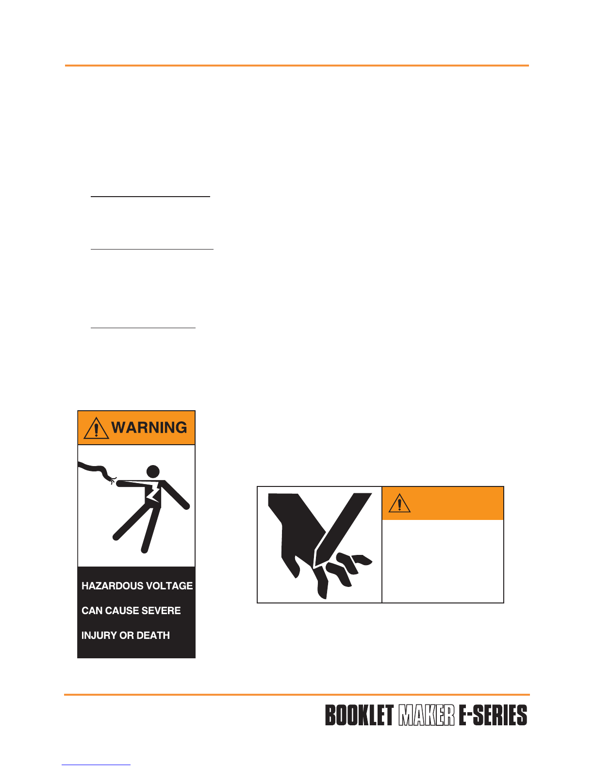
Please pay attention to the description of the following pictograms:
Caution:
on a yellow background,
indicates a hazardous situation that can cause small or severe injury.
Warning:
on a orange background,
is used to indicate a hazardous situation which has some probability of death or severe
injury. Warning should not be considered for property damage accidents unless personal
injury risk is present.
Danger:
on a red background,
indicates a hazardous situation with a high risk of death or severe injury. The ‘danger’ sign
does not apply to accidents causing material damage, unless they can cause personal
injury.
Orange background, warning.
This label is located near the main power unit. It warns
of a high risk of electrocution when opening the power
supply box with a risk of severe injury or death.
WARNING
KEEP HANDS CLEAR
CAN CAUSE
SEVERE INJURY
Orange background, warning.
This label is located near the knife of the folding machine. It
warns of a high risk of severe hand injuries when
placing your hands under the knife.

Operator manual
Page 9 - 8 Initial version : 11/08
Lastest revision : -
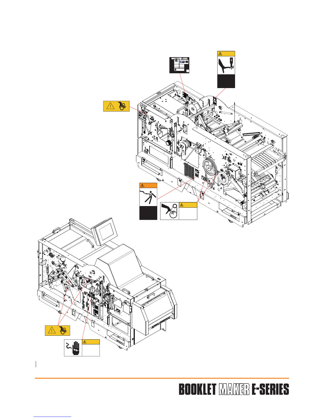
Yellow background, caution.
This label is located near the knife of the press-cutter. It indicates
a high risk of severe injury if you put you hands under the knife.
Yellow background, caution.
This label is located near the wheel-work of the chain. It
indicates a high risk of injury to your fingers if they get
stuck between the wheel-work and the chain.
Yellow background, caution.
This label is located near the stapling head. It indicates a
high risk of severe injury to your fingers if you place them
under this head.
CAUTION
CAUTION
KEEP HANDS CLEAR
DO NOT OPERATE
WITHOUT SAFETY
COVERS IN PLACE

Operator manual
Page 9 - 9 Initial version : 11/08
Lastest revision : -
Yellow background, caution.
This label is located near the primary
shaft. It indicates a high risk of severe
injury to your fingers if they get stuck
in the belt
Yellow background, caution.
This label is located at the rear of the machine under the
safety cover. It indicates that the machine may not be
operated, under no circumstances, without the safety
covers being in place.
Yellow background, caution.
This label is located near the
main power supply.
It indicates that this power supply
cabinet may only be opened by
qualified personnel.
CAUTION
DO NOT OPERATE
WITHOUT SAFETY
COVERS IN PLACE
CAUTION
ELECTRICAL HAZARD
AUTHORIZED SERVICE
PERSONNEL ONLY
CAUTION
PINCH POINTS
KEEP HANDS CLEAR
Operator manual
Page 9 - 10 Initial version : 11/08
Lastest revision : -
3.2 Warning pictograms location
CAUTION
PINCH POINTS
KEEP HANDS CLEAR
WARNING
HAZARDOUS VOLTAGE
CAN CAUSE SEVERE
INJURY OR DEATH
CAUTION
KEEP HANDS CLEAR
DO NOT OPERATE
WITHOUT SAFETY
COVERS IN PLACE
MADE IN BELGIUM BY c.p. bourg S.A.
Ottignies Tel : +32 / 10 / 62 22 11 Fax : +32 / 10 / 61 36 38 9.139.829
MODEL
VOLTS
A
Hz
:
:
:
:
AGR-PA BME AGR-PABME
120 230
8 5
60 50
LISTED
I.T.E.
E125337
Referto Installation M anual
formotor connection
CAUTION
ELECTRICAL HAZARD
AUTHORIZED SERVICE
PERSONNEL ONLY

Operator manual
Page 9 - 11 Initial version : 11/08
Lastest revision : -
CAUTION
PINCH POINTS
KEEP HANDS CLEAR
CAUTION
CAUTION
DO NOT OPERATE
WITHOUT SAFETY
COVERS IN PLACE
CAUTION
DONOT OPERATE
WITHOUTSAFETY
COVERSIN PLACE
CAUTION
ELECTRICAL HAZARD
AUTHORIZED SERVICE
PERSONNEL ONLY
MADE IN BELGIUM BY c.p. bourg S.A.
Ottignies Tel : +32 / 10 / 62 22 11 Fax : +32 / 10 / 61 36 38 9.139.830
MODEL
VOLTS
A
Hz
:
:
:
:
TR BME TR BME
120 230
5 3
60 50
LISTED
I.T.E.
E125337
Refer to Installation Manual
for motor connection
Operator manual
Page 9 - 12 Initial version : 11/08
Lastest revision : -
3.3 BME description
3.3.1 Technical characteristics
Verify that you electrical service corresponds with one of the following:
USA 120V AC +/- 10% - 60Hz
EUROPE 230V AC +/- 10% - 50Hz
JAPAN 230V AC +/- 10% - 60Hz
Check your environmental conditions.
This machine is designed for the following environment:
Storage and transport:•
Temperature: -34°C through 60°C / -30°F through 140°F
Relative humidity: 5 through 90% RH
Altitude: -31m through 12 192m / -100 ft.through 40 000 ft.
Atmospheric pressure: ≥56kPa (420mm Mercury)
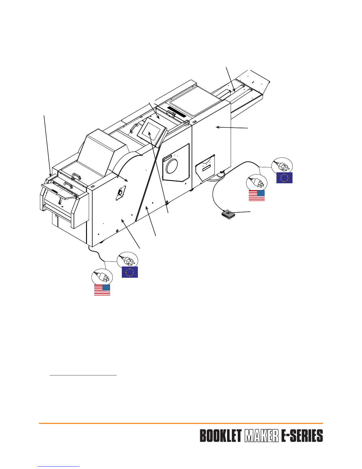
User interface
Output conveyor
Input
REAR
LEFT
RIGHT
Operator side
FRONT
Upper reception tray
Stitcher (AGR)
ITE with BSTd+/BST-e
Folder (PA)
Trimmer (TR)
optional
Pedal to activate the
motion of the
conveyor (only
available with TR
module)
Output
Operator manual
Page 9 - 13 Initial version : 11/08
Lastest revision : 02/10
Work envi• ronment:
Temperature: 10°C (50°F) through 32°C (89.6°F)
Relative humidity: 40 through 85% RH
Power consumption:•
BTU output: from 2525 to 5700 BTU/H (complete system).•
Noise level: 70 db.•
Warning: Never remove the power cord while the machine is turned ON.
General
- Input/Output paper path: 860 mm without ITE and 610 mm with ITE.
- Variable speed of input motor.
- Centered registration: the BME positions itself to the center of the processed paper
format from the upstream registered equipment thanks to a transversal motorization.
- Full automatic adjustment depending on the format.
- Upper reception tray for top/edge/corner stitched booklet or poor booklet.
- Paper path jam, open baffles and open covers detectors.
- Detection of output conveyor full and trim waste container full.
- Machine is managed via the U.I.
- Different component position (heads/stops/joggers/PA press/TR press/holding wheels/
conveyor motion) is automatic depending on the defined job in the U.I.
- Fine adjustments possible while machine is working.
Stitcher
- The BME is equipped with 2 or 4 stitching heads.
- Equipped with ISP stitching heads featuring toolless change over self threading cassette
for stitch wire supply.
- On demand before delivery, the machine can be equipped with 2 or 4 Hohner heads
compatible with various diameter wire.
- Hohner heads convertible to loop stitch model via optional upgrade kit.
- Heads supplied with wire n°25 (EU) or 25 Gauge (US).
- Capacity of 50.000 stitches (75 gsm, 2 to 30 sheets).
Folder
- Booklets folded between the belts with a fold crush device.
- Booklet pressure adjustment.
Trimmer
- Upper and lower knives, without heel, can be easily replaced.
- Equipped with a system to ease the ejection of the chips.
- Waste bin that can be emptied while machine is working.
Consumption
Machines
Maximum In operation
230 V
50Hz
120 V
60Hz
230 V
50Hz
120 V
60Hz
AGR-PA 994 W 924 W 740 W 760 W
AGR-PA-TR 1675 W 1480 W 1110 W 1160 W

Operator manual
Page 9 - 14 Initial version : 11/08
Lastest revision : -
Output Conveyor
- Operator adjustment on U.I. conveyor advance step per book.
- Conveyor full detector (can be disabled).
- Device to offset the sets - offset every N sets, with N adjustable by operator on U.I.
- Automatic positioning of set holding wheels, based on finished set dimensions.
- Pedal to activate the motion of the conveyor (only available with TR module).

Operator manual
Page 9 - 15 Initial version : 11/08
Lastest revision : -
3.3.2 Stitching possibilities depending on paper width
On demand before delivery, the machine can be equipped with 4 heads brackets but only 2
heads. In this case it could be upgraded with 2 additional heads.
Corner stitching
The middle of the stitch is placed at
14mm from the side (left or right) of the
sheet and at 7mm from the lead edge of
the sheet. You must clutch and activate
the used head (s).
To avoid severe mechanical interferences which could lead to serious damages,
unclutch the unused heads when it is asked on User Interface.
Paper width 119 (4.7") to 218 mm
(8.6 ")
218 (8.6") to 268
(10.5")
268 (10.5") to 370
(14.6")
Machine Type Stitch
position
2 heads on 2
bracket heads
2 saddle or
top Space between stitches = 80 (3.1") to paper width - 28 mm
1 corner YES (left or right)
2 heads on 4
bracket heads*
2 saddle or
top
"Space between
stitches =
80 (3.1") to paper
width - 28mm (middle
brackets**)"
"Space between
stitches =
80 (3.1") to 190
(7.5") (middle
brackets**)"
"Space between stitches
=
80 (3.1") to 190 (7.5")
(middle brackets**) and
240 (9.4") to paper width
- 28 mm (outside
brackets**)"
1 corner YES (left or right
middle brackets**) Not possible YES (left or right outside
brackets**)
4 heads
2 saddle or
top
"Space between
stitches =
80 (3.1") to paper
width - 28mm (middle
heads)"
"Space between
stitches =
80 (3.1") to 190
(7.5") (middle
heads)"
"Space between stitches
=
80 (3.1") to 190 (7.5")
(middle heads) and
240 (9.4") to paper width
- 28 mm (outside heads)"
4 saddle or
top Not possible
"Space between middle
stitches =
80 (3.1") to paper width
-188 mm"
1 corner YES (left or right
middle head) Not possible YES (left or right outside
heads **)
* Requires installation of heads on proper brackets (middle or outside ones)
** Stitching head position at installation
7mm
0.27"
14mm
0.5"
7mm
0.27"
14mm
0.5"

Operator manual
Page 9 - 16 Initial version : 11/08
Lastest revision : 09/09
3.3.3 Technical specifications
Note:The figures below represent what the BME is capable of producing.
The device feeding paper to the BME may alter those specifications.
Type of paper
Any type of paper except paper with a window or transparent paper.
Coated / uncoated from 60 to 160 gsm.
Covers from 80 to 250 gsm (up to 350 gsm if the covers are creased).
Paper format
Productivity
- Up to 5000 sets/hour, in each case (stitching only, stitching & folding or stitching,
folding and trimming).
- Based on A4 format 80 gsm.
Note: The specified paper thickness figures are given for guidance only. The actual
performances of the machine will depend on the nature of the paper and covers used.
Min = 180mm (7.1")
Max = 600mm (23.6")
Min = 119mm (4.7")
Max = 370mm (14.6")
Min = 70mm (2.8")
Max = 300mm (11.8")
Min = 119mm (4.7")
Max = 370mm (14.6")
Min = 170mm (6.7")
Max = 300mm (11.8")
Min = 119mm (4.7")
Max = 370mm (14.6")
Max. trim = 25mm (1")
Saddle stitching Top/side stitching
Folding/Trimming
For a format higher than or
equal to 190mm (95mm
folded)
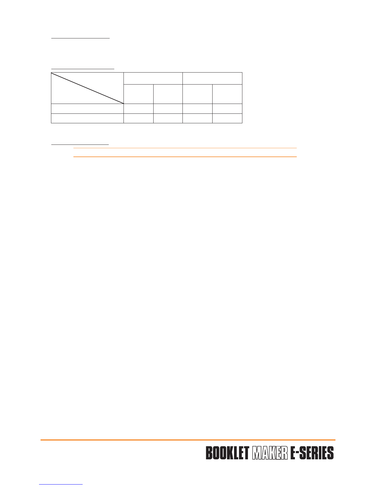
PRODUCTIVITY
(books / h)
(over lap 15 mm)
EURO USA
A4 A3 8,5 / 11 11 / 17
5 sheets 5050 4350 5150 4300
10 sheets 4700 4100 4850 4050
15 sheets 4450 3900 4600 3900
Operator manual
Page 9 - 17 Initial version : 11/08
Lastest revision : 02/10
Booklet thickness
Saddle stitching (middle of the sheet stitching) fold and cut :
- from 2 to 30 sheets of 75 gsm or equivalent thickness (cover included) Maximum 3 mm.
- Top or corner stitching (without either fold or cut) :
from 2 to 55 sheets of 80 gsm or equivalent thickness (cover included).
Stitcher
See “Stitching possibilities depending on paper width”.
Folder
Maximum pressure by default, pressure can be decrease through U.I. to avoid cover marking/
crackles.
Trimmer
Waste bin capacity: 8000 paper strips of 80 gsm with a cut of 5mm.
The waste bin can be emptied without stopping the machine during 50 cycles, after which the
machine will stop.
Conveyor
Capacity: 42 sets (A4 format) of 10 sheets (80gsm) - theoretical values.
Motion step:
Offset set device:
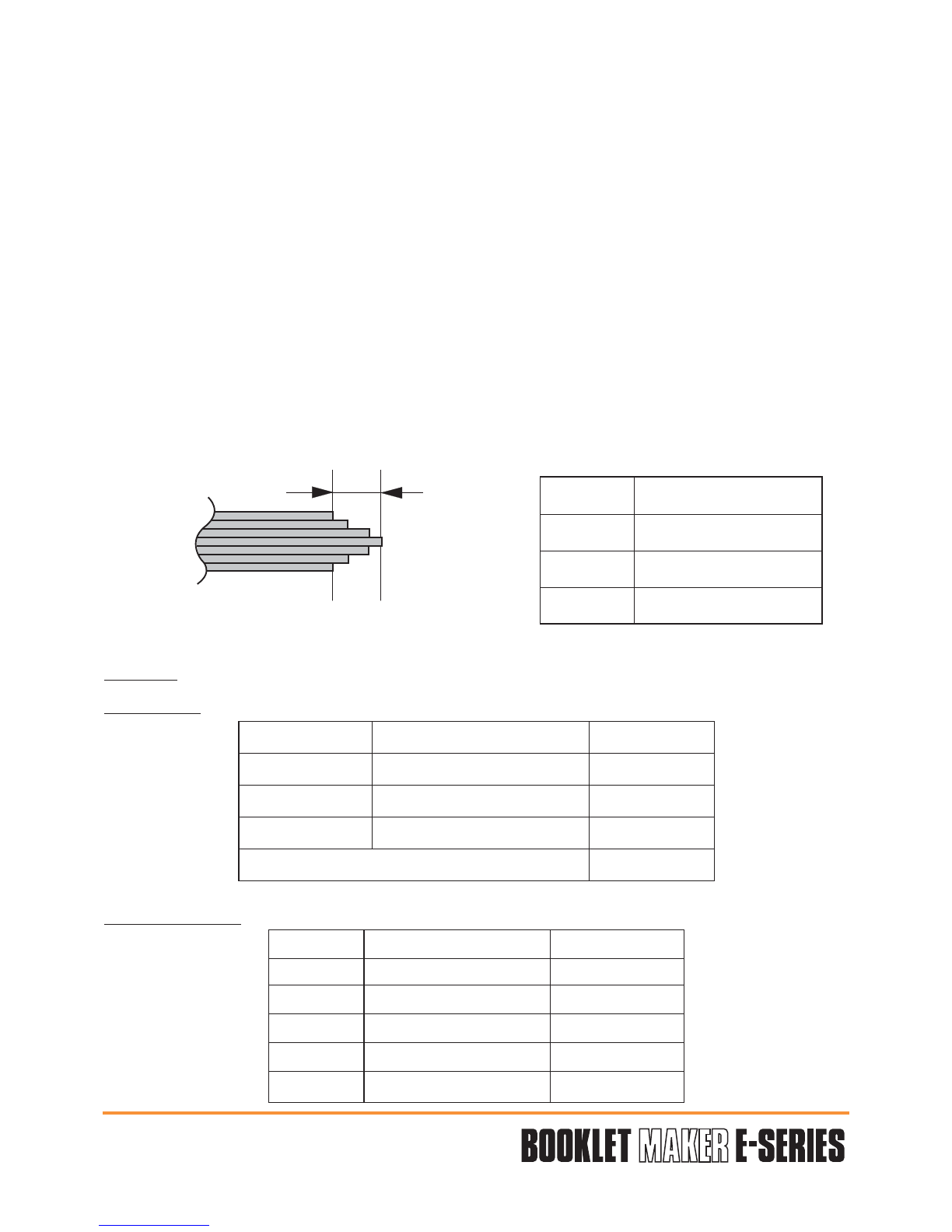
Length of the cut
Min. 0 mm (0 in.)
Max. 25 mm (1 in.)
Standard 5 mm (0.2 in.)
Step Value Value U.I.
Minimum 20 ± 10 mm 1
Maximum 330 ± 40 mm 29
By default 8
Conveyor does not stop 30
Offset Value on U.I.
No offset 1
Minimum Offset of 2nd set 2
Offset of 3rd set 3
Offset of nth set 11
Maximum Offset of 250th set 250

3.3.4 Stitch and Fold offset possibilities
Operator manual
Page 9 - 18 Initial version : 11/08
Lastest revision : 02/09
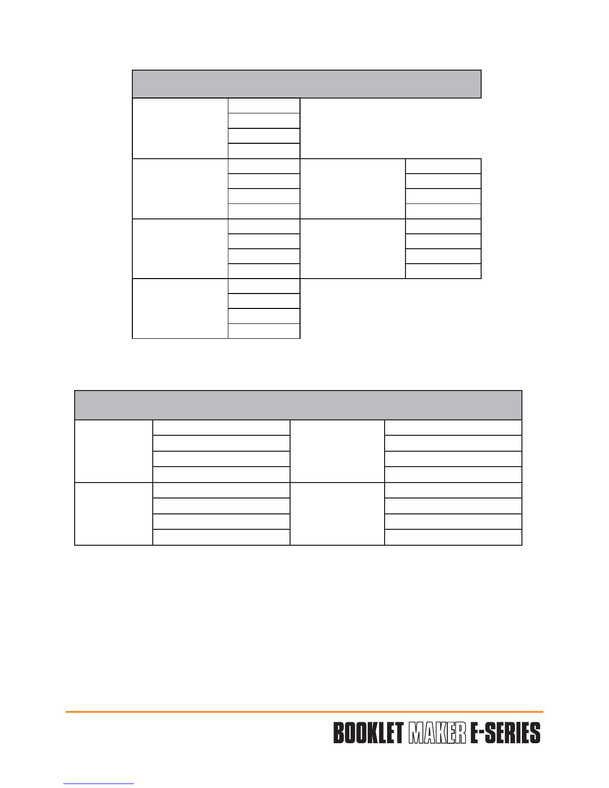
MINIMUM AND MAXIMUM OFFSET FOR EU FORMATS (mm)
A3
(portrait) :
A= -90 SRA3
(portrait) :
A= -75
B= 90 B= 75
C= -90 C= -75
D= 120 D= 135
A4
(portrait) :
A= -58,5 A4
(landscape) :
A= -15 SRA4
(portrait) :
A= -70 SRA4
(landscape) :
A= -22,5
B= 58,5 B= 15 B= 70 B= 22,5
C= -151,5 C= -195 C= -140 C=-187,5
D= 58,5 D= 15 D= 70 D= 22,5
A5
(portrait) :
A= - 15
B= 15
C= -195
D= 15
CD
(portrait) :
A= -35
B= 35
C= -175
D= 35
Operator manual
Page 9 - 19 Initial version : 11/08
Lastest revision : 02/09
MINIMUM AND MAXIMUM OFFSET FOR USA FORMATS (inch)
17x11 (portrait) : A= -3,31
B= 3,31
C= -3,31
D= 4,96
11x8,5 (portrait) : A= -1,96 8.5x11 (landscape) : A= -0,71
B= 1,96 B= 0,71
C= -6,31 C= -7,56
D= 1,96 D= 0,71
10x8 (portrait) : A= -1,46 8x10 (landscape) : A= -0,46
B= 1,46 B= 0,46
C= -6,81 C= -7,81
D= 1,46 D= 0,46
CD (portrait) : A= -1,38
B= 1,38
C= -6,89
D= 1,38
MINIMUM AND MAXIMUM OFFSET FOR JAPANESE FORMATS (mm)
B4 (portrait) : A= -92 B4 (landscape) : A= -38,5
B= 92 B= 38,5
C= -118 C= -171,5
D= 92 D= 38,5
B5 (portrait) : A= -38,5 B5 (landscape) : A= -1
B= 38,5 B= 1
C= -171,5 C= -209
D= 38,5 D= 1

Operator manual
Page 9 - 20 Initial version : 11/08
Lastest revision : -
3.4 BM-e Process Description
a. Paper path
b. Jam clearance
Table of contents


