Caliber RG4D User manual

Installation guide
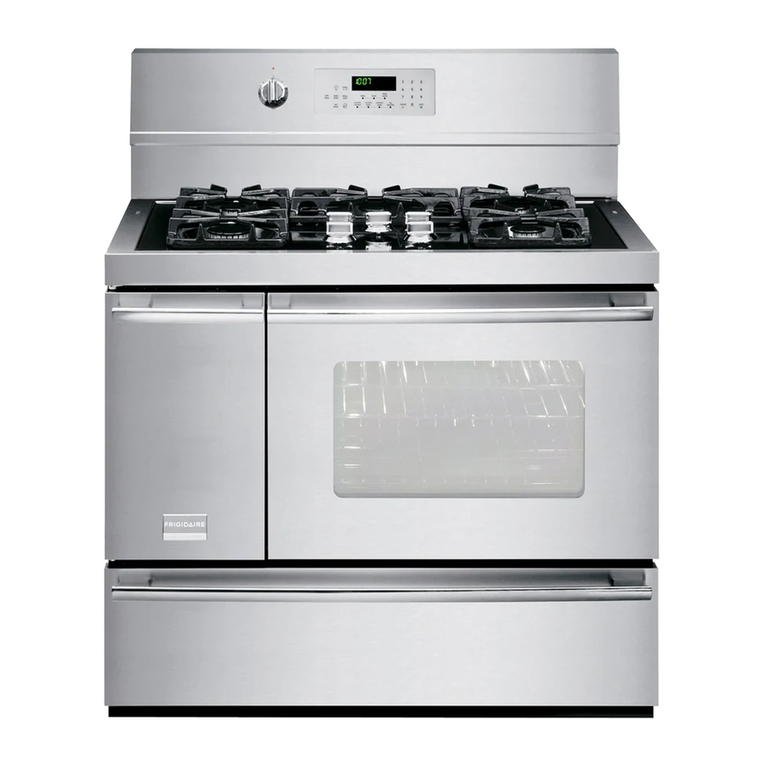
Professional 36” Range
RG3F, RG3G, RG3R & RG36
models
Professional 48” Range
RG4D, RG4F, RG4G, RG4R &
RG4T models
Professional 72” Range
RG68BFTGD & RG66BFT2GD
models
Professional 36” Rangetop
CG3F, CG3G, CG3R & CG36
models
Professional 48” Rangetop
CG4D,CG4F, CG4G, CG4R &
CG4T models

1
Do not store or use gasoline or other flammable vapors and
liquids in the vicinity of this or any other appliance.
NEVER use this appliance as a space heater to heat or warm
the room. Doing so may result in carbon monoxide
poisoning and overheating of the appliance.
WHAT TO DO IF YOU SMELL GAS
• Do not try to light any appliance.
• Do not touch any electrical switch.
• Do not use any phone in your building.
• Immediately call your gas supplier from a neighbor’s
phone. Follow the gas supplier’s instructions.
• If you cannot reach your gas supplier, call the fire
department.
Installation and service must be performed by a qualified
installer, service agency or the gas supplier.
WARNING
If the information in this manual is not followed exactly, a fire
or explosion may result causing property damage, personal
injury or death.
WARNING
To reduce the risk of tipping the appli-
ance, the appliance must be secured
by properly installed anti-tip device
packed with the appliance.
• A child or adult can tip the range
and be killed.
• Install the anti-tip device to the
structure by fastening the sup-
plied bracket to the floor and
wall following the instructions for
installing anti-tip device.
• Engage the anti-tip device.
• Re-engage the anti-tip device if
the range Is moved.
• See Installation Instructions for
details.
Failure to do so can result in death or
serious burns to children of adults.
A MESSAGE TO OUR CUSTOMERS 2
SAFETY PRACTICES AND PRECAUTIONS 3
MODELS 6
PLANNING THE INSTALLATION 9
UNPACKING AND HANDLING 11
VENTILATION REQUIREMENTS 13
INSTALLING ANTI-TIP DEVICE 14
CABINET PREPARATION 15
BACKGUARD INSTALLATION 21
ELECTRICAL CONNECTIONS 21
GAS HOOK-UP 22
TEST AND ADJUSTMENTS 24
CLEANING EXTERIOR SURFACES 25
INSTALLER FINAL CHECKLIST 26
SERVICE 27
FRENCH WARNINGS 28
TABLE OF CONTENTS

32
Thank you for selecting this professional Range. Because of this appliance's unique features we have
developed this Installation Guide. It contains valuable information on how to properly install your new
appliance for years of safe and enjoyable cooking.
For your convenience, product questions can be answered by a Caliber Appliances Customer Care
Representative by phone:
NOTE: Please write the Model and Serial Numbers on this page for reference on the label on the
back of the unit (middle to bottom right-hand corner of the oven frame or below backguard of the
rangetop).
MODEL NUMBER_________________________ SERIAL NUMBER __________________________
NOTE: Inspect the product to verify that there is no shipping damage. If any damage is detected, call
the shipper and initiate a damage claim. Caliber Appliances is not responsible for shipping damage.
DO NOT discard any packing material (box, pallet, straps) until the unit has been inspected.
WARNING!
Improper installation, adjustment alteration, service or maintenance can cause property damage, in-
jury or death. Read the installation, operating and maintenance instructions thoroughly before using,
installing or servicing this appliance. A risk of the appliance tipping over exists if the appliance is not
installed in accordance with installation instructions.
WARNING!
To reduce the risk of injury to persons in the event of a rangetop grease fire, observe the following:
Turn burner off first. Smother flames with a close-fitting lid, cookie sheet, metal tray, baking soda or
use a dry chemical or foam-type fire extinguisher. Be careful to prevent burns. If the flames do not
go out immediately, evacuate and call the fire department. Never pick up a flaming pan- You may be
burned. DO NOT USE WATER ON GREASE FIRES, including wet dishcloths or towels -a violent steam
explosion will result. Use an extinguisher ONLY if:
1. You know you have a Class ABC extinguisher, and you already know how to operate it.
2. The fire is small and contained in the area where it started.
3. The fire department is being called.
4. You can fight the fire with your back to an exit.
WARNING!
Installer: leave this manual with the customer.
Customer: please retain this manual for future reference and for the local inspector's use.
When properly cared for, your new Caliber Appliance has been designed to be a safe, reliable
cooking appliance. When using this restaurant caliber appliance, use it with extreme care, as this type
appliance provides intense heat and can increase the accident potential. Basic safety precautions must
be followed when using kitchen appliances, including the following:
• Read the user guide, which came with this appliance, thoroughly before using your new
appliance. This will help to reduce the risk of fire, electric shock, or injury to persons.
• Begin by insuring proper installation and servicing. Follow the installation instructions in this
manual. Be sure to have a qualified technician install and ground this appliance before using.
• Have the installer show you where the gas supply shut-off valve is located.
• If you smell gas, the installer has not done a proper job of checking for leaks. Shut the gas to the
appliance off and follow the instructions on the inside front cover of this manual. Do not attempt
to find the leak yourself. This must be done by a qualified service technician only.
• If by some chance a burner goes out and gas escapes, open a window or a door to let the room
air out. Do not attempt to use the appliance until the gas has had time to dissipate. Follow the
instructions on the inside front cover of this manual.
• This appliance has been factory assembled for natural or LP gas. It should be correctly adjusted
from the factory for the type of gas that is used.
• Do not repair or replace any part of this appliance unless it is specifically recommended in this
manual. All other servicing should be referred to a qualified technician.
• Children should not be left alone or unattended in an area where appliances are in use. They
should never be allowed to turn knobs, push buttons, sit or stand on, and/or touch any part of an
appliance while in operation.
• Children in walkers, or children crawling can be attracted to the oven door handle and may grab
and open the oven door. This can result in injury from the door being pulled open on a child, or
severe burns if the oven is in use and hot.
WARNING!
Do not store Items of Interest to children above or at the back of any appliance. Children could be
seriously Injured if they should climb onto the appliance to reach these items.
• Never store anything in the oven or on the rangetop. Flammable materials can catch fire, plastic
items may melt or ignite and other types of items could be ruined.
• Do not hang articles from any part of the appliance or place anything against the oven. Some
fabrics are quite flammable and may catch on fire.
• If the appliance is near a window be certain the curtains do not blow over or near the rangetop
burners; they could catch on fire.
• Keep rugs and mats well clear of the base of the range.
• Do not use water on grease fires. Turn all burners "OFF ... , then smother fire with baking soda or
use a dry chemical or foam-type fire extinguisher.
• Never let clothing, pot holders, or other flammable materials come in contact with, or too close
to, any burner or burner grate until it has cooled. Fabric may ignite and result in personal injury.
• Be certain to use only dry pot holders: moist or damp pot holders on hot surfaces may cause
burns from steam. Do not use a towel or other bulky cloth in place of pot holders. Do not let pot
holders touch hot burners, or burner grates.
A MESSAGE TO OUR CUSTOMERS SAFETY PRACTICES AND PRECAUTIONS

54
• For personal safety, wear proper apparel, loose fitting garments or hanging sleeves should never
be worn while using this appliance. Some synthetic fabrics are highly flammable and should not
be worn while cooking.
• Do not use aluminum foil to line any part of the oven or rangetop. This will cause heat to be
trapped underneath it. This trapped heat can upset the cooking performance and can damage
the finish of the oven or the rangetop parts.
WARNING! NEVER cover any slots, holes or passages in the oven bottom or cover
an entire rack with materials such as aluminum foil. Doing so blocks airflow through the oven and may
cause carbon monoxide poisoning. Aluminum foil linings may also trap heat, causing a fire hazard.
This appliance is for cooking. Never use the oven or rangetop to warm or heat a room. This could
damage the rangetop or oven parts.
• When using the rangetop: Do not touch the burner grates or the immediate surrounding area.
Areas adjacent to the burners may become hot enough to cause burns.
• When using the oven: Do not touch the interior surfaces of the oven, the exterior area
immediately surrounding the door or the back trim. The surfaces directly above the oven door
may be hot if the oven has been operated with the door open, or if something has prevented the
door from sealing.
• Never leave the rangetop unattended when using high flame settings. When cooking with high
flame settings, boil-overs may cause smoking and greasy spillovers may ignite. More importantly,
if the burner flames are smothered by a severe boil-over which affects the igniter, unburned gas
will escape into the room.
• Only certain types of glass, heat-proof glass-ceramic, ceramic, earthen ware, or other glazed
utensils are suitable for rangetop use. Some utensils may break with sudden temperature
changes. Use only on low or medium flames settings according to the manufacturer's directions.
The use of professional utensils is recommended.
• Do not heat unopened food containers; a build up of pressure may cause the container to burst.
• During cooking, set the burner control so that the flame heats only the bottom of the pan and
does not extend beyond the bottom of the pan. This could heat and/or melt the handles, and
may increase cooking time.
• Always use utensils that have flat bottoms large enough to cover the burner. The use of
undersized utensils will expose a portion of the flame to direct contact and may result in ignition
of clothing.
• To minimize burns, ignition of flammable materials and unintentional spill overs, position handles
of utensils inward so they do not extend over adjacent work areas, cooking areas, or the edge of
the rangetop.
• Hold the handle of the pan to prevent movement of the utensil when stirring or turning food.
• Grease is flammable. Let hot grease cool before attempting to handle it. Avoid letting grease
deposits collect around the rangetop burners. Clean after each use or boil over.
• Do not remove the grease drip-pan from the griddle or grill until completely cool.
• For proper lighting and performance of the rangetop burners, keep the burner ports clean. It may
be necessary to clean these when there is a boil over or when the burner does not light, even
though the electronic igniters click.
• Do not use the grill for cooking excessively fatty meats or products which promote flare-ups. Do
not use cooking utensils on the grill.
• Clean the rangetop with caution. Avoid steam burns; do not use a wet sponge or cloth to clean
the rangetop while it is hot. Some cleaners produce noxious fumes if applied to a hot surface.
Follow directions provided by the cleaner manufacturer.
• Be sure all the range and/or rangetop controls are turned off and the appliance is cool before using
any type of aerosol cleaner on or around the appliance. The chemical that produces the spraying
action could, in the presence of heat, ignite or cause metal parts to corrode.
• Place oven racks in desired position while the oven is cool. If a rack must be moved while the oven
is hot, do not let the pot holders contact the hot interior of the oven.
• Use care when opening the oven door; let hot air or steam escape before removing or replacing
foods.
• Do not rub, damage, move or remove the door gasket. It is essential for a good seal during baking.
Wash the gasket with hot water only.
• Clean the ventilator hood and filters above the range or rangetop frequently so grease from
cooking vapors does not accumulate on them. The filters can be cleaned in a dishwasher or dish
drawer. Follow directions provided by ventilation manufacturer for cleaning.
• Turn the ventilator “OFF” in case of fire or when intentionally “flaming” liquor or other spirits on the
rangetop. The blower, if in operation, could unsafely spread the flames.
• DO NOT obstruct the flow of combustion or ventilation air to the appliance. Be sure a fresh air
supply is available.
• For safety reasons and to avoid damage to the appliance never sit, stand, or lean on the oven door
or cooking surface.
• Service should only be done by authorized technicians. Technicians must disconnect the power
supply before servicing this appliance.
WARNING!
California Proposition 65 - The burning of gas cooking fuel generates some by-products which are known
by the State of California to cause cancer or reproductive harm. California law requires businesses to warn
customers of potential exposure to such substances. To minimize exposure to these substances, always
operate this unit according to the manufacturer’s instructions and provide good ventilation to the room
when cooking with gas.
REQUIREMENTS FOR HOOK-UP TO GAS SUPPLY
• The gas supply connections should be made by a qualified technician in accordance with local
codes or ordinances. In the absence of a local code, the installation must conform to the latest
edition of National Fuel Gas Code ANSI Z.223.1 (Warning: this appliance must be installed by a
licensed plumber or gas fitter when within the Commonwealth of Massachusetts).
• A manual shut-off valve (supplied by the installer) must be installed in an
accessible location in the gas line external to the appliance for the purpose of
turning on or shutting off gas to the appliance.(In Massachusetts such shut-
off valves should be approved by the Board of State Examiners of Plumbers &
Gas Fitters.) The shut-off valve must be located within 6 feet (1.8 meters) of the
appliance it serves.
Important!
Caliber Appliances recommends installing the manual shut-off valve in a location readily accessible by the
customer, so that gas to the appliance can be shut off in an emergency situation. However, the appliance
must not be modified In any way to accommodate such placement.
• The gas supply line must not protrude beyond the back of the appliance as this would prevent the
product from being pushed completely against the wall.
• Make sure the gas supply is turned off at the wall valve before connecting the appliance.
• Leak-testing of the appliance shall be conducted according to the manufacturer's instructions. See
instructions in section 'Test and adjustments'.
SAFETY PRACTICES AND PRECAUTIONS SAFETY PRACTICES AND PRECAUTIONS
76
MODELS MODELS
48”models
Professional 48” Range Models:
RG4D, RG4F, RG4G, RG4R & RG4T
Professional 48” Rangetop Models
(surface cooking only - no ovens):
CG4D,CG4F, CG4G, CG4R & CG4T
36"models
Professional 36” Range Models:
RG3F, RG3G, RG3R & RG36
Professional 36” Rangetop Models
(surface cooking only - no ovens):
CG3F, CG3G, CG3R & CG36

98
MODELS
72"models
Professional 72” Range Models:
RG68BFTGD & RG66BFT2GD
IMPORTANT INSTALLATION INFORMATION
The range Is tested In accordance with ANSI Z21.1 Standard for Household Cooking Gas Appliances.
The range must be Installed In conjunction with a suitable overhead vent hood. (See section 'Ventila-
tion
Requirements'). Due to the professional high heat capacity of this unit, particular attention should be
paid to the hood and duct work installation to ensure it meets local building codes. To eliminate risk
of burns or fire by reaching over heated surface units, cabinet storage located above the surface units
should be avoided.
All range and rangetop models have an integral island trim with a hight of 2 5/8” from countertop
level. - See section 'Backguard Installation'.
All range and rangetops have a standard 2 5/8" integral island trim.
• For all ranges and rangetops, the full backguard may be purchased separately from Caliber
(see specifications information below in Fig.1).
Full Backguard Specifications
48” Range
and Rangetop
Models
Width Height
47 7/8” 33 3/8”
36” Range
and Rangetop
Models
35 7/8” 33 3/8”
72” Range
Models
71 7/8” 33 3/8”
Check local building codes for the proper method of range installation. Local codes vary.
Installation, electrical connections, and grounding must comply with all applicable codes. In the
absence of local codes, the range should be Installed in accordance with the latest edition of
National Fuel Gas Code ANSI Z223.1 and National Electrical Code ANSI/ NFPA 70.
Be sure that the unit being installed is set up for the kind of gas being used. The gas range is
shipped from the factory set and adjusted for Natural Gas or LP (propane), depending on the
specific model ordered. Verify that the range Is compatible with the gas at the installation site
before proceeding further. Return range to dealer if the unit is not set for site gas supply.
PLANNING THE INSTALLATION
35 7/8” for 36” models
47 7/8” for 48” models
71 7/8" for 72" models
33 3/8”
for
all
models
Fig. 1
RG68BFTGD
Eight burners, French Top &
Griddle
Caliber Pro Range (R) Configurations 72”
RG66BFT2GD
Six burners, French Top &
Double Griddle

1110
RECOMMENDED INSTALLATION SEQUENCE
Install components in the following order:
1. Locate and level range according to range and rangetop installation instructions.
5. Follow vent hood manufacturer's installation instructions to install vent hood.
6. Connect gas and electric connections and slide range into position.
NOTE: A manual gas shut-off valve must be installed. See section 'Gas Hook-up~
Steps 2,3 & 4 are only relevant if you are installing a Wall Mount Full Backguard:
2. Measure distance from floor to top of island trim on range, adding 1/4” for backguard
clearance.
3. Transfer this measurement to the wall. This will mark the bottom of your backguard.
4. From this line measure 33 3/8” up wall to mark the top of a wall mount full backguard. This is
the minimum height that the bottom of your vent hood can be installed.
UNPACKING AND HANDLING
WARNING!
420-630 lb
190-285 kg
Extremely Heavy
Proper equipment and adequate manpower must be used in moving
the range to avoid personal injury or damage to the unit or the floor.
The unit is heavy and rests on adjustable steel legs. Rangetops are less
than half of the weight of the ranges.
Failure to follow this advice may result in damage or personal injury.
WARNING!:
DO NOT lift range by the oven door handles!!
WARNING!:
DO NOT remove the grill or griddle assemblies
MOVING AND PLACING THE RANGE
The ranges have shipping weights varying from 420 lbs. to 630 lbs. less approx. 50 lbs. after removal
of packing material. It is recommended that the door(s), grates, and front kick panel be removed to
facilitate handling. This will reduce the weight for ease of handling.
It may be necessary to remove the oven door(s) to pass through some doorways. With the door(s)
removed, a 29-1/2” wide opening is required. Without removing the door, a 32” wide opening is
required. Remove the outer carton and packing material from the shipping base.
PLANNING THE INSTALLATION
MOVING AND PLACING THE RANGE (cont.)
Anti-tip device should be Installed (see section 'Installing
anti-tip device' for instructions). The professional range
should be transported by a dolly close to its final location.
The range can be tipped back and supported on the rear
legs while the dolly is removed. The floor under the legs
should be protected (wood strips, carpet, paneling, etc.)
before pushing the unit back into position.
Gas connections should be made before the range is slid
Into the cabinet opening (see section 'Gas hook-up'). If
installing a full backguard with the range, it should also
be installed before the range is placed in its final position
(see sections 'Planning the Installation' and 'Backguard
Installation'). For proper performance, the professional
range should be level. Flooring in cabinet opening must be
at the same level as flooring located In front of the cabinets.
To achieve a flush fit of the range to adjoining countertops,
it will be necessary to have level cabinets (front to back, and
left to right across opening of the range). After checking
the countertops for level and before sliding the range into
place, measure the distance from the floor to the top of
the counter work surface. In the rear left and right corners.
Adjust the corresponding rear corner of the range to an
equal height of the counter, as the rear leveling legs are
not accessible once the range is pushed into place. Once
the range Is in place, the front leg levelers can be accessed
to level the front of the range. Replace the kick panel (Fig.
2a) and oven doors by reversing the procedure described
further below. It is Important that the two screws retaining
the kick panel are secure to prevent accidental access to live
electrical components and wires (Fig. 2b).
To remove the kick panel:
Remove two screws at the top of the kick panel (Fig. 2c).
Due to the weight, a dolly with soft wheels should be used
to move this unit. The weight must be supported uniformly
across the bottom (Fig. 3).
Kick Panel
(range models)
UNPACKING AND HANDLING
Fig. 2a
Fig. 2b
Fig. 3
Fig. 2c

1312
To remove door:
WARNING!:
Do not lift oven door by the handle -this will cause
damage! Be sure the oven and door are cool before you
begin to remove the door!
1. Open the door completely.
2. Unlock the door hinges by rotating the lock forward
(Fig. 4a).
3. Once both hinges are unlocked, gently close the door
until approximately halfway closed. Grabbing the sides
of the door and gently lifting up and slightly forward, the
door will unlatch from the hinge.
4. Continue to lift and pull the door away from the range.
To re-install door:
1. Position the door in approximately halfway open
position.
2. Simply place the hinge tongue into the hinge slots
{See Fig. 4b).
3. Push the door into the slots until you feel them fall
into the latches.
4. Open the door completely and rotate the locks into
the closed position (Fig. 4c).
5. Close the oven door.
Fig. 4a Hinge retainer clip comes down for
the unlocked position
Fig. 4b Hinge assembly
Fig. 4c Hinge retainer clip in locked position
UNPACKING AND HANDLING
A suitable exhaust hood must be installed above the range. The following chart indicates the
minimum blower capacity recommended for hood ventilation.
Ventilation Unit Standard Counter Installation
Recommendations
Island Installation
Recommendations
HOOD 23” Deep x Unit Width 30” Deep x 36” at Bottom
BLOWER
72” Range and Rangetops 1400 CFM 1400 CFM
48” Range and Rangetops 1200 CFM 1200 CFM
36” Range and Rangetops
600 -1200 CFM*
600 -1200 CFM
* 36" and 48" range and rangetops featuring a grill require a 1200 CFM ventilation unit and 1400 CFM for 72" ranges.
CAUTION:
Ventilation hoods and blowers are designed for use with single wall ducting. However, some local
building codes or inspectors may require double wall ducting and/or a damper. Consult local building
codes and/or local agencies, before starting, to ensure that hood and duct installation will meet local
requirements.
Hood blower speeds should be variable to reduce noise and loss of heated or air conditioned household
air when maximum ventilation is not required. Normally, the maximum blower speed is only required
when using the grill or the self-cleaning cycle.
For best smoke elimination, the lower edge of the hood should be installed a minimum of 30" to a
maximum of 36" above the range cooking surface, (see section 'Cabinet Preparation'). If the hood
contains any combustible materials (e.g. a wood covering) it must be a minimum of 36" above the
cooking surface.
Due to a high volume of ventilation air, a source of make-up air {outside replacement air) is
recommended. This is particularly important for tightly sealed and insulated homes. A reputable heating
and ventilating contractor should be consulted.
VENTILATION REQUIREMENTS
INSTALLATION ANTI-TIP DEVICE
A
3 3/8” Anti-tip
Device
Back view of anti-tip device
Fig. 5a Fig. 5b
A

1514
All ranges must have an anti-tip device correctly installed as per the following instructions. If you pull the
range out from the wall for any reason, make sure that the device is properly engaged when you push
the range back against the wall. The bracket captures the post of the leveling leg to prevent tipping. If it
is not, there is a risk of the range tipping over and causing injury if you or a child stand, sit or lean on an
open oven door.
INCLUDED PARTS:
4 #10 x 2” wood screws, (1) Anti-tip bracket, and (1) Installation Instructions.
INSTALLING THE KIT:
Instructions are provided for wood and cement floors. Any other type of construction may require special
installation techniques as deemed necessary to provide adequate fastening of the Anti-tip bracket to the
floor and wall. The use of this bracket does not preclude tipping of the range when not properly installed.
Install the anti-tip bracket to the ground and wall 3 3/8” measuring from the left or right side edge of
the range to the centerline of the bracket. The bracket engages the post of the leveling leg to prevent
tipping.
WOOD CONSTRUCTION:
Place the bracket against the back wall, into the right rear corner where the range is to be located. Leave
a gap between the wall (or side of range} and the bracket 3 3/8” to the centerline of the bracket if the
cabinet cut out matches the size of the range at 36” or 48” (see Fig. 5a and 5b on page 13). Drill (4) 1/8"
diameter pilot holes in the center of the small holes. A nail or awl may be used if a drill is not available.
Fasten the bracket securely to the floor and wall.
For all installations:
Fasten the bracket to the back wall using the four holes on the back of the bracket. Follow the method
described in 'wood construction'.
Model
Series
RG3F-36, RG3G-36, RG3R-36
& RG36-36
RG4D-48, RG4F-48, RG4G-48,
RG4R-48 & RG4T-48
RG68BFTGD-72,
RG66BF2GD-72
“A” in
Fig. 5a
& 5b on
page
13
3 3/8” from right side edge of
the range to the centerline of
bracket pictured, but can also
be placed to 3 3/8” from the
left side edge of the range.
WARNING!
• A child or adult can tip the range
and be killed.
• Install the anti-tip device to the
structure.
• Engage the anti-tip device.
• Re-engage the anti-tip device if
the range Is moved.
• See Installation Instructions for
details.
Failure to do so can result in death or
serious burns to children of adults.
INSTALLATION ANTI-TIP DEVICE
1. The range is a free standing unit. If the unit is to be placed adjacent to cabinets, the
clearances shown in the following diagrams are required. The same clearances apply to
island installations.
2. The range can be placed in various positions with respect to the cabinet front, with the front
frame either flush or projecting, depending on the countertop depth.
3. The electrical and gas supply should be within the zones shown in the following diagrams.
4. A manual shut-off valve {supplied by the installer) must be installed in an accessible location
in the gas line external to the appliance for the purpose of turning on or shutting off gas to
the appliance. (In Massachusetts such shut-off valves should be approved by the Board of
State Examiners of Plumbers & Gas Fitters.) The shut-off valve must be located within 6 feet
(1.8 meters) of the appliance it serves.
Important!
Caliber Appliances recommends Installing the manual shut-off valve In a location readily
accessible by the customer, so that gas to the appliance can be shut off in an emergency
situation. However, the appliance must not be modified in any way to accommodate such
placement.
5. The maximum depth of over head cabinets installed on either side of the hood is 13”.
6. Any openings in the wall behind the range and in the floor under the range must be sealed.
7. Always keep the appliance area clear and free from combustible materials, gasoline and
other flammable vapors and liquids.
8. Do not obstruct the flow of combustion and ventilation air to the unit.
9. The horizontal surfaces of the rangetop trim must not be below countertop level.
CABINET PREPARATION

1716
Supply area dimensions
(see diagram figures 6-12 for further
clarification)
RG68BFTGD-72
RG66BFT2GD-72
RG4D-48
RG4F-48
RG4G-48
RG4R-48
RG4T-48
RG3F-36
RG3G-36
RG3R-36
RG36-36
CG4D-48
CG4F-48
CG4G-48
CG4R-48
CG4T-48
CG3F-36
CG3G-36
CG3R-36
CG36-36
Adistance from left or right edge of
range to supply area Fig. 9, 10 & 11
3” 3” 3” N/A N/A
Bdepth of supply areas (i.e.
maximum protrusion of gas
connection from wall) Fig. 6 & 7
3” 3” 3” N/A N/A
Cheight of gas and electrical supply
area (from floor) Fig. 8, 9, 10 & 11
16” 16” 16” 16” 16”
CABINET PREPARATION CABINET PREPARATION
LOCATION OF ELECTRICAL & GAS SUPPLY- RG3, RG4 & RG6 RANGE MODELS
Fig. 9 location of electrical and gas supply - RG3 36” RANGE MODELS
A
C (16")
A
C (16")
C
Fig. 6 range supply
areas for RG3/RG4
models
Fig. 8 location of
electrical and gas
supply - CG3/CG4
RANGETOP MODELS
B
LOCATION OF ELECTRICAL & GAS
SUPPLY- CG4 & CG3 RANGETOP MODELS
C
DEPTH OF RANGE SUPPLY AREAS
Fig. 7 range supply
areas for RG6
models
Fig. 10 location of electrical and gas supply - RG4 48” RANGE MODELS
Fig. 11 location of electrical and gas supply - RG6 72” RANGE MODELS
Fig. 12 side
view of RG3/
RG4/ RG6
Range Models
A
B
ANTI-TIP
BRACKET
lOCATION
ANTI-TIP
BRACKET
lOCATION
COUNTER
TOP
HEIGHT
COUNTER
TOP
HEIGHT

1918
Fig. 12 Cabinetry dimensions rangetops
see diagrams
following for
gas connection
details
CABINET PREPARATION
Cabinetry dimensions for rangetop models
CG4D (48”)
CG4F (48”)
CG4G (48”)
CG4R (48”)
CG4T (48”)
CG3F (36”)
CG3G (36”)
CG3R (36”)
CG36 (36”)
Aminimum width of ventilation hood installed above range 48” 36”
Bminimum vertical distance between countertop and cabinet
extending above counter
18” 18”
Cminimum clearance from left and right edge of range to
nearest vertical combustible surface
12” 12”
Dminimum clearance from cooking surface to:
-combustible surface centered above the cooking surface
36” 36”
Emaximum overall depth of overhead cabinetry 13” 13”
F1
F2
width of cabinetry opening
countertop edge width opening (see detail above)
46 /”
48”
34 /”
36”
Gmaximum height from bottom of countertop front cut out to
top countertop (note: rangetop surface height should never be
lower than countertop height)
8 /”
8 /”
A
B
CD
E
F2 G
F1
Rangetop
Specifications
CALIBER INDOOR PROFESSIONAL RANGETOP SERIES SPECIFICATIONS
48” Rangetop
Models
36” Rangetop
Models
Full height to vent hood backsplash with shelf accessory models also available in Stainless Steel with Stainless Steel Shelves
see diagrams
following for
gas connection
details
CABINET PREPARATION
Fig. 11 Cabinetry dimensions ranges
Cabinetry dimensions for range models
RG68BFTGD
(72”)
RG66BF2GD
(72”)
RG4D (48”)
RG4F (48”)
RG4G (48”)
RG4R (48”)
RG4T (48”)
RG3F (36”)
RG3G
(36”) RG3R
(36”) RG36
(36”)
Aminimum width of ventilation hood installed above range 36” 48” 36”
Bminimum vertical distance between countertop and
cabinet extending above counter
18” 18” 18”
Cminimum clearance from left and right edge of range to
nearest vertical combustible surface
12” 12” 12”
Dminimum clearance from cooking surface to:
-combustible surface centered above the cooking surface
36” 36” 36”
Emaximum overall depth of overhead cabinetry 13” 13” 13”
Fminimum width of cabinetry opening 72” 48” 36”
Gmaximum height from floor to countertop is adjustable
leveling: (note: rangetop surface height should never be
lower than countertop height)
35 /” to
37”
35 /” to
37”
35 /” to
37”
Hmaximum depth from wall to cabinet front 28 /” 28 /” 28 /”
A
B
CD
E
F
G
H
Range
Specifications
CALIBER INDOOR PROFESSIONAL RANGE SERIES SPECIFICATIONS

2120
BACKGUARD INSTALLATION
The backguard is located as shown in Fig. 13 on page 20. Secure the backguard to the wall behind
the range (full backguards). Specific instructions for installation can be found packaged with the
backguard. See also "Planning The Installation" section.
For all models, Caliber Appliances backguards are sold separately.
ELECTRICAL CONNECTIONS
Important!
Always disconnect electric supply cord from the wall outlet or service
disconnect before servicing this appliance.
Observe oil governing codes and ordinances when grounding, in
absence of which, observe National Electrical Code ANSI/NFPA No. 70.
ELECTRICAL CONNECTIONS - RG6, RG4/CG4 & RG3/CG3 MODELS
The electrical supply must be a correctly polarized 120 volt AC, 60 Hz,
single phase circuit suitable for the maximum current draw of the model,
as detailed in the table below. Please verify your model's current draw by
checking the rating label on the back of the range.
REQUIRED GROUNDING METHOD - RG6, RG4/CG4 & RG3/CG3 MODELS
This appliance is factory equipped with a power supply cord with a three-prong grounding plug (with
polarized parallel blades). It must be plugged into a mating grounding-type receptacle, connected
to a correctly polarized 120 volt circuit. If the circuit does not have a grounding type receptacle, it is
the responsibility and obligation of the installer to have the existing receptacle changed to a properly
grounded and polarized receptacle in accordance with all applicable local codes and ordinances by a
qualified electrician. In the absence of local codes and ordinances, the receptacle replacement shall be
in accordance with the National Electrical Code.
Note: The third prong should not under ANY circumstances, be cut or removed.
RG6, RG4/CG4 and RG3/CG3
Fig. 14 The rating label is
located on the back of the
range and rangetop.
Asdenedinthe•NationalFuelGasCode
(ANSI Z223.1, Latest Edition). The horizontal surfaces of the range
top (rangetop) trim must not be below countertop level.
CABINET PREPARATION
Standard Installation:
Use the appropriate range
mount. Full backguard models
are available from Caliber, but
not required.
Fig. 13 full backguard specifications

2322
GAS HOOK-UP
Important!
Caliber Appliances recommends installing the manual shutoff valve in a location
readily accessible by the customer, so that gas to the appliance can be shut off in an
emergency situation. However, the appliance must not be modified in any way to
accommodate such placement.
• The gas supply line must not protrude beyond the back of the appliance.
• Make sure the gas supply is turned off at the wall valve before connecting the
appliance
• Leak-testing of the appliance shall be conducted according to the
manufacturer’s instructions. See instructions in section ‘Test and adjustments’.
• The appliance must be isolated from the building’s gas supply piping system
by closing its individual manual shut-off valve during any pressure testing of
the gas supply piping system at test pressures equal to or less than 1/2 psig
(3.5kPa.). The appliance and its individual shut-off valve must be disconnected
from the gas supply piping system during any pressure testing of the system
at the test pressures in excess of 1/2 psig (3.5kPa.). When checking the
manifold gas pressure, the inlet pressure to the regulator should be at least
7.0” W.C. for natural gas or 12.0” for LP.
• The flex line for the gas supply must be metal and be approved for appliance
use by a certifying agency (CSA, CGA, or UL). Never use a hose made of
rubber or other synthetic material, as the heat may cause the hose to melt
and develop leaks.
• When hooking up the gas supply from the wall hard pipe to the range
hard pipe, installation length of flex line between range/wall hard piping
must accommodate range being pulled from wall for cleaning or servicing
purposes. When range is pulled from wall, no strain should occur at range or
wall hard pipe connections
An emergency shut-off
valve for the gas line in
the front of the range
units have additionally
been provided by
Caliber in Fig. 17 for
easy maintenance
issues, however a
installer-supplied shut-
off valve should still
be provided for safety
issues. Fig. 17
GAS REQUIREMENTS
Verify the type of gas supplied to the location. The range is shipped from the factory set up
and adjusted for Natural Gas or LP (propane), depending on the specific model ordered from
the Factory. Verify that the gas type printed on the range or rangetop’s “rating plate” and
packaging is compatible with gas supply at the installation site before proceeding further.
This rating plate is located on the rear right side of the range or rangetop. Return the range
to the dealer if the unit is not set for the gas supplied at the site.
Each range is shipped with a 3/4” NPT gas regulator and the rangetops with a 1/2” NPT
gas regulator. Both are set for 5 inches W.C. natural gas or 10 inches W.C. LP. On any LP 36”
range or 36”/48” rangetop unit it is acceptable to connect the appliance to 1/2” NPT supply.
For 48” ranges the minimum recommended gas supply size is 3/4” NPT or larger.
Natural Gas Supply Pressure: 6 to 9 inches W.C.
LP (Propane) Gas Supply Pressure: 11 to 14 inches W.C. If the LP gas supply comes from a
remote LP cylinder the supply must be equipped with a high pressure regulator that reduces
the supply pressure to the appliance to a maximum of 14 inches W.C.
REQUIREMENTS FOR HOOK-UP TO GAS SUPPLY
• The gas supply connections should be made by a qualified technician in accordance
with local codes or ordinances. In the absence of a local code, the installation must
conform to the latest edition of National Fuel Gas Code ANSI Z.223.1 (Warning:
this appliance must be installed by a licensed plumber or gas fitter when within the
Commonwealth of Massachusetts).
• A manual shut-off valve (supplied by the installer) must be installed in an accessible
location in the gas line external to the appliance for the purpose of turning on or
shutting off gas to the appliance (Fig.16a). (In Massachusetts such shut-off valves
should be approved by the Board of State Examiners of Plumbers & Gas Fitters.) The
shut-off valve must be located within 6 feet (1.8 meters) of the appliance it serves.
Fig. 16b Installer-supplied gas line with shut-off valve
to be connected to 3/4” NPT male pipe gas line in
the back of Caliber range models and 1/2” NPT male
pipe gas line in the back of rangetop models.
GAS HOOK-UP
Fig. 16a Manual shut-off valve.

2524
TEST AND ADJUSTMENTS
Check for the proper burner flame characteristics.
Burner flames should be blue and stable with no yellow
tips, excessive noise or lifting of the flame from the
burner. If any of these conditions exist, check that the
air shutter (oven burner only) (Fig. 20) or burner ports
are not blocked. If this condition persists, contact a
qualified technician.
The oven burner flames should be 3/8” to 5/8” (Fig.
21). The infrared broil burner flames should be
approximately 1/4” high over the entire burner screen
(Fig. 22).
The stainless steel surfaces may be cleaned by wiping with a damp soapy cloth or sponge.
Any liquid soap (like Dawn or Stainless Steel Magic) will remove fingerprints and smears.
Do not use steel wool as it will scratch this surface.
CLEANING EXTERIOR SURFACES
Fig. 22
GRIDDLE AND GRILL BURNERS (SOME MODELS ONLY)
Check for the proper burner flame characteristics and adjust air
shutters if necessary (Fig. 20). Each valve and air shutter is individually
tested and adjusted prior to shipment. Normally adjustment is not
required, however, vibration during transit, gas conversion or variations
in the local gas supply may make minor adjustments necessary. Burner
flames should be blue and stable with no yellow tips, excessive noise
or lifting of the flame from the burner. If any of these conditions
exist, check that the air shutter or burner ports are not blocked. If this
condition persists, adjust the air shutter as required. If the flame is too
yellow, indicating insufficient air, adjust the shutter counterclockwise
to increase air inlet. If the flame is noisy or tends to lift away from the
burner, indicating too much air, turn the shutter clockwise to reduce
air. The griddle flames should be 3/8” to 5/8”. The grill burner flames
should be 3/8” to 5/8” (Fig. 21).
INFRARED BROIL AND OVEN BAKE BURNERS
(MAIN OVENS IN RANGE RG6/RG4/RG3 MODELS ONLY)
CAUTION:
The oven infrared broiler burner has no air shutter and Is not
adjustable. The oven bake burner has an air shutter and is adjustable.
It is necessary to operate the oven broiler for 20-30 minutes to
eliminate the harsh odor of the insulation binder. This must be done
before using the range for the first time and with proper ventilation.
Fig. 20
air shutter
Fig. 21
RANGETOP BURNERS
The rangetop burners are not adjustable. Proper operation is achieved when the correct orifices for
gas supply are installed at the factory, based on model ordered.
When installing the burner port ring, be sure that the locating pin in the bottom side of the brass
star ring are properly aligned with the locating notch and center holes on the top side of the
burner base. Incorrect alignment will produce a potentially dangerous flame and poor burner
performance.
Note:
Burner flames should be blue and stable with no yellow-tipping (some yellow-tipping is normal
with LP gas), excessive noise, or lifting of flame from the burner (Fig. 18).
RANGETOP BURNER LIGHTING NOTE
The rangetop burners have an infinite number of heat settings and there are no fixed positions on
the control knobs between HI, LO and SIM. To turn the rangetop burner on, push in on the control
knob and turn it counterclockwise to the "LO" position. An audible clicking sound will be heard.
When the gas has been ignited by the electronic spark igniter, turn the knob to the desired setting
(Fig. 19).
Note:
The igniter will continue to click until a flame is present. If the rangetop burner does not ignite,
check the spark igniter by listening for a clicking sound. If you do not hear the igniter click, turn off
the burner. Check for a tripped circuit breaker, blown fuse, or poor wire connection to the igniter.
WARNING!:
When turning on any rangetop burner, be sure to stop at the "LO" position before turning the
burner to a flame setting for cooking. If the burner is not lit and it is turned beyond the "HI"
position, to HI there will be a burst of flame when the burner does light. This could cause burns or
damage to the surrounding countertop.
Fig. 18 Connect burner flame characteristics
Fig. 19
OFF
LO
SIM
LEAK TESTING:
• After final gas connection is made, turn on manual gas valve
and test all connections in gas supply piping for gas leaks with
a soapy water solution. During this test all appliance gas valves
have to be closed.
• In order to avoid property damage or serious personal injury,
never use a lighted match or open flame. If a leak is present,
tighten joint or unscrew, apply more joint compound, tighten
again and retest connection for leak.
•
WARNING!:
For warranty coverage, Caliber Appliances requires that burner
adjustments be made by a qualified technician at the time of
installation. Extreme care should be used when adjustments are made
after installation. IMPROPER OR LACK OF ADJUSTMENT WILL VOID
YOUR WARRANTY.
TEST AND ADJUSTMENTS
HI

2726
Important!
• Service should only be done by authorized technicians. Before servicing this appliance, the
technician must disconnect it from the power supply.
To obtain service, please contact Caliber Appliances at (714) 848-1349 or go to our website at
www.caliberappliances.com and choose “CONTACT” to email us the service needed. Before you call,
please have the following information ready:
• Model and serial number (located on the label above the kick panel on the right)
• Date of installation
• A brief description of the problem
Your satisfaction is of the utmost importance to us. If a problem cannot be resolved to your satisfaction,
Write:
Caliber Appliances
Attention: Customer Care
17812 Metzler Lane
Huntington Beach, CA 92647
BEFORE YOU CALL FOR SERVICE:
1. Is the circuit breaker tripped or the fuse blown?
2. Is there a power outage in the area?
SERVICEINSTALLER FINAL CHECKLIST
GENERAL
q Placement of unit.
q Specified clearance maintained to cabinet surfaces.
q Unit Level - front to back, side to side.
q All packaging material and tie straps removed.
q Radiant tray placed in grill unit (if equipped). The grill grate is in place.
ELECTRICAL
q Receptacle with properly rated over-current protection is provided for service cord connection.
q Adequate ground connection.
q Front kick panel in place and two (2) screws secure.
GAS SUPPLY
q Connection: 1/2” NPT with a minimum 1/2” flex line for LP 36” range or 36”/38” rangetop units
only and 3/4” NPT with a minimum 3/4” flex line for 48” ranges. Site gas supply is compatible with
range model, and sufficient pressure is available (see section 'Gas Hook-Up').
q The pressure regulator which is connected to the manifold is 3/4” NPT gas regulator and set for
5.0" W.C. for natural gas or 10.0” W.C. for LP.
q Manual gas shut-off valve installed in an accessible location.
q Unit tested and free of gas leaks.
OPERATION
q All internal packing materials removed. Check below the grate and inside the oven.
q If used on LP gas, verify that pressure regulator, orifice hoods, air shutters, and valve jets have
been set for use with LP gas.
q Grill compartment seated and does not rock (if equipped).
q Bezels centered on burner knobs and knobs turn freely.
q Each burner lights satisfactorily, both individually and with other burners operating at the same
time.
q Flame adjustment made on air shutter of each oven, griddle, or grill burner.
q Griddle is level and does not rock (if equipped).
q Oven door hinges seated and door opens and closes properly.
q Burner grates correctly positioned, level, and do not rock.
q Griddle flame correct.
q Grill flame correct.
q Rangetop burner flame correct.

2928
MESURES DE SÉCURITÉ ET DE PRÉCAUTION
• Utilisez seulement des gants isolants secs : les gants humides sur des surfaces chaudes peuvent
provoquer des brûlures causées par la vapeur. N’utilisez pas de serviette ou de linge épais à la
place de gants isolants. Ne laissez pas les gants isolants toucher les brûleurs ou leurs grilles.
• Pour assurer votre propre sécurité, habillez-vous de façon appropriée. Ne portez jamais de
vêtements ou de manches lâches lorsque vous utilisez l’appareil. Certains tissus synthétiques sont
extrêmement inflammables et ne doivent pas être portés pendant la cuisson.
• Ne recouvrez aucune partie du four ou de la table de cuisson avec du papier aluminium. C’est un
isolant thermique qui peut emprisonner la chaleur, laquelle peut alors affecter la performance de
la table de cuisson et endommager la finition du four ou des pièces de la table de cuisson.
AVERTISSEMENT! Ne recouvrez JAMAIS les fentes, trous ou passages situés au bas du four et évitez de
recouvrir entièrement une grille avec des matériaux tel que le papier d’aluminium. Cela a pour effet de bloquer
la circulation d’air à l’intérieur du four et peut causer un empoisonnement à l’oxyde de carbone. Le papier
d’aluminium peut également emprisonner la chaleur et causer ainsi un risque d’incendi
• Cet appareil électroménager est destiné à la cuisson. N’utilisez jamais le four ou la table de
cuisson pour réchauffer ou chauffer une pièce. Une telle utilisation peut endommager les pièces
de la table de cuisson ou du four.
• Durant l’utilisation de la table de cuisson : ne touchez pas les grilles des brûleurs ou les surfaces
adjacentes. Ces surfaces peuvent devenir suffisamment chaudes pour provoquer des brûlures.
• Durant l’utilisation du four, évitez de toucher les surfaces intérieures du four, la surface extérieure
autour de la porte et la garniture arrière. Les surfaces situées directement au-dessus de la porte
du four peuvent être chaudes si le four a fonctionné avec la porte ouverte ou si quelque chose a
empêché la porte de se fermer.
• Ne laissez jamais la table de cuisson sans surveillance lorsque vous cuisinez á flamme haute. Un
débordement par bouillonnement pourrait produire de la fumée et un déversement graisseux
qui pourrait prendre feu. Et, ce qui est plus grave, si les flammes des brûleurs sont étouffées par
un débordement important affectant l’allumeur, le gaz non brûlé s’échappera dans la pièce.
• Seuls certains types d’ustensiles en verre, vitrocéramique calorifugée, céramique, poterie ou
émaillés sont appropriés pour être utilisés sur la table de cuisson. Certains types d’ustensiles
peuvent se briser a la suite de changements de température soudains. Utilisez-les seulement à
feu doux ou moyen selon les instructions du fabricant. II est recommandé d’utiliser des ustensiles
de cuisine professionnels.
• Ne chauffez pas de contenant de nourriture fermé car la pression pourrait s’accumuler et le faire
exploser.
• Durant la cuisson, réglez la commande du brûleur de sorte que la flamme ne chauffe que le fond
du récipient et ne le dépasse jamais. Cela pourrait sinon chauffer ou faire fondre les poignées.
• Servez-vous toujours d’ustensiles à fond plat suffisamment larges pour couvrir les brûleurs.
L’utilisation d’ustensiles trop petits risque d’offrir un contact direct à la flamme et de mettre le feu
aux vêtements.
• Afin de réduire le risque de brûlures, d’allumage de matériaux inflammables et de déversement
involontaire, tournez les poignées des ustensiles vers l’intérieur afin qu’elles ne surplombent pas
les surfaces de travail adjacentes, les zones de cuisson et le bord extérieur de la table de cuisson.
• Tenez la poignée du récipient afin d’empêcher tout mouvement de l’ustensile lorsque vous
retournez ou remuez la nourriture.
FRENCH WARNINGSFRENCH WARNINGS
MESURES DE SÉCURITÉ ET DE PRÉCAUTION
Votre nouvel appareil Caliber fonctionnera de manière sûre et fiable pendant des années si vous
en prenez bien soin. Faites extrêmement attention quand vous utilisez cet appareil de niveau
professionnel, car il dégage une chaleur intense et peut augmenter les risques d’accidents. Vous
devez respecter des consignes de sécurité élémentaires durant l’utilisation d’appareils de cuisine,
dont celles-ci:
• Veuillez lire attentivement le guide d’utilisation avant d’utiliser votre nouvel appareil. Ceci vous
permettra de réduire les risques d’incendie, de choc électrique ou de blessures.
• Commencez par vous assurer que l’installation et l’entretien sont effectués correctement. Suivez
les instructions d’installation fournies avec cet appareil. Avant d’utiliser l’appareil, confiez son
installation et sa mise à la terre à un technicien qualifié.
• Demandez-lui de vous montrer l’emplacement du robinet d’arrêt de l’alimentation de gaz.
• Si vous sentez une odeur de gaz, cela signifique que l’installateur n’a pas vérifié correctement s’il
y avait des fuites. Coupez le gaz à l’appareil et suivez les instructions sur la couverture intérieure
de ce manuel. N’essayez pas de trouver la fuite vous-même. Ceci doit être fait par un technicien
qualifié de service seulement.
• Si jamais un brûleur s’éteint et laisse s’échapper du gaz, ouvrez la fenêtre ou la porte pour évacuer
l’air. N’essayez pas d’utiliser l’appareil avant que le gaz ne se soit complètement dissipé. Suivez les
instructions sur la couverture intérieure de ce manuel.
• Cet appareil électroménager a été monté en usine pour être utilisé avec du gaz naturel ou
propane. II doit être réglé correctement en usine selon le type de gaz utilisé.
• Ne réparez pas ni ne remplacez aucune pièce de cet appareil, sauf indication contra ire du manuel.
Tout autre travail d’entretien doit être confié à un technicien qualifié.
• Les enfants ne doivent pas être laissés seuls ou sans surveillance dans un endroit ou l’on utilise
des appareils électroménagers. II ne faut jamais les laisser tourner ou enfoncer des boutons, ni
s’asseoir ou se tenir debout sur ces appareil ou les toucher lorsqu’ils sont en marche.
• Des enfants en marchette ou à quatre pattes peuvent être attires par la poignée de la porte et la
saisir pour ouvrir la porte du four. Ils pourraient alors se blesser si la porte est ouverte ou se brûler
sérieusement si le four fonctionne et qu’il est chaud.
AVERTISSEMENT!
Évitez de ranger sur les appareils ou à l’arrière des articles pouvant attirer les enfants. Les enfants peuvent être
blessés sérieusement s’ils grimpent sur l’appareil pour atteindre ces articles.
• Ne rangez jamais rien dans le four ni sur la table de cuisson. Des matériaux inflammables
pourraient prendre feu, des éléments en plastique pourraient fondre ou s’enflammer et d’autres
types d’objets pourraient être détruits.
• Ne suspendez aucun article sur l’appareil et ne placez aucun objet centre le four. Certains
matériaux sont très inflammables et pourraient prendre feu.
• Si l’appareil se trouve près d’une fenêtre, assurez-vous que les rideaux sont suffisamment éloignés
des brûleurs de la table de cuisson; ils pourraient prendre feu sinon.
• Garder les paillassons et largement à l’écart de la base de la cuisinière.
• Ne versez pas d’eau sur les feux de graisse. ÉTEIGNEZ tous les brûleurs, puis étouffez le feu avec
du bicarbonate de soude ou à l’aide d’un extincteur à poudre ou à mousse.
• Ne laissez jamais des vêtements, gants ou autres matériaux inflammables en contact ou à
proximité d’un brûleur ou d’une grille de brûleur tant que ces derniers n’ont pas refroidi. Les tissus
peuvent s’enflammer et causer des blessures.

3130
MESURES DE SÉCURITÉ ET DE PRÉCAUTION
EXIGENCES CONCERNANT LE BRANCHEMENT DU GAZ
• Toutes les connexions d’alimentation en gaz doivent être effectuées par un technicien qualifié
conformément aux codes et règlements en vigueur. En l’absence d’une réglementation locale,
l’installation doit être conforme à la dernière édition du National Fuel Gas Code ANSI Z223.1.
(mise en garde : dans les limites de l'État du Massachusetts, cet appareil doit être installé par un
monteur d’installation au gaz ou plombier autorisé).
• Un robinet d’arrêt manuel (fourni par l’installateur) doit être installé dans un endroit accessible
de la canalisation externe de l’appareil pour pouvoir ouvrir ou couper l’alimentation en gaz a
l’appareil (au Massachusetts, de tels dispositifs doivent être approuvés par le Board of State
Examiners of Plumbers & Gas Fitters). Le robinet d’arrêt doit etre situé a mains de 6 pieds (1.8
mètres) de l’appareil qu’il sert.
Important!
Caliber recommande d’installer le robinet d’arrêt manuel dans un endroit facilement accessible par le client pour
couper l’alimentation en gaz en cas d’urgence. Cependant, l’appareil ne doit pas être modifié de quelque façon
pour adapter à un tel placement.
• La conduite d’alimentation en gaz ne doit pas dépasser l’arrière de l’appareil car ceci empêcherait
l’appareil d’être poussé complètement centre le mur.
• Avant de brancher l’appareil, prenez soin de couper le gaz par le robinet d’arrêt.
• La vérification des fuites doit être effectuée conformément aux instructions du fabricant. Voir la
section ‘Essai et réglages’ pour les instructions.
FRENCH WARNINGS
ROBINET D'ARRÊT (FOURNI
PAR L'INSTALLATEUR) EN
POSITION 'OUVERT'
TUYAU D'ALIMENTATION EN GAZ
FRENCH WARNINGS
MESURES DE SÉCURITÉ ET DE PRÉCAUTION
• La graisse est inflammable. Laissez toute graisse chaude refroidir avant d’essayer de la manipuler.
Évitez de laisser la graisse s’accumuler autour des brûleurs de la table de cuisson. Nettoyez après
chaque utilisation ou déversement.
• Pour assurer un bon allumage et une bonne performance des brûleurs de la table de cuisson,
gardez leurs ports dans un état propre. II peut s’avérer nécessaire de nettoyer ceux-ci en cas
de débordement ou lorsque le brûleur ne s’allume pas, même si les allumeurs électroniques
cliquent.
• N’utilisez pas le gril pour cuire des viandes ou des produits très gras pouvant alimenter les
flammes. N’utilisez pas d’ustensiles de cuisson dans le gril.
• Nettoyez la table de cuisson avec précaution. Évitez de vous brûler à la vapeur: n’utilisez pas
d’éponge ou de linge mouillé pour nettoyer l’appareil alors qu’il est encore chaud. Certains
produits de nettoyage dégagent des vapeurs nocives au contact d’une surface chaude. Respectez
le mode d’emploi du fabricant du produit de nettoyage.
• Assurez-vous que les boutons de la cuisinière ou de la table de cuisson sont fermes et que
l’appareil est froid avant d’utiliser des nettoyant aérosol sur l’appareil ou à proximité. L’élément
chimique qui produit le jet de vaporisation peut, en présence de chaleur, s’enflammer ou
provoquer la corrosion des parties métalliques.
• Placez les grilles de four à la position voulue quand le four est froid. Si vous devez déplacer une
grille alors que le four est encore chaud, ne laissez pas les gants isolants toucher l’intérieur chaud
du four.
• Faites attention lorsque vous ouvrez la porte du four; laissez s’échapper l’air chaud ou la vapeur
avant de retirer ou remplacer les aliments.
• Évitez de frotter, endommager, déplacer ou en lever le joint de la porte, car il est essentiel a
l’obtention d’une bonne cuisson. Lavez le joint avec de l’eau chaude seulement.
• Nettoyez fréquemment la hotte et les filtres de ventilation surplombant la cuisinière ou table de
cuisson afin d’empêcher toute accumulation de graisse provenant des vapeurs de cuisson. Le
filtre peut être nettoyé dans un lave-vaisselle ou un dishdrawer. Respectez le mode d’emploi du
fabricant du produit de ventilation en ce qui a trait au nettoyage.
• ÉTEIGNEZ le ventilateur en cas d’incendie ou si vous flambez intentionnellement des liqueurs ou
des spiritueux sur la table de cuisson. Si le ventilateur est en marche, il pourrait en effet répandre
les flammes.
• ÉVITEZ de bloquer la circulation de l’air de combustion ou de ventilation. Assurez toujours un
apport d’air frais.
• Pour des raisons de sécurité et pour ne pas endommager l’appareil, évitez de vous asseoir, de
vous tenir debout ou de vous appuyer contre la porte du four ou la surface de cuisson.
• Les réparations doivent être effectuées par des techniciens agréés uniquement. Ceux-ci doivent
débrancher le bloc d’alimentation avant de travailler sur l’appareil.
AVERTISSEMENT!
Proposition 65 de la Californie- L’incinération de gaz de cuisson génère des sous-produits considérés par
l’État de Californie comme pouvant causer le cancer ou des malformations congénitales. Les lois de Californie
exigent que les entreprises avertissent leurs clients qu’ils risquent d’être exposés à de telles substances. Pour
minimiser l’exposition à ces substances, faites toujours fonctionner l’appareil conformément aux instructions
du fabricant et assurez une bonne ventilation lorsque vous cuisinez au gaz.

Copyright © Caliber Appliances 2019.
All rights reserved.
The product specifications in this
booklet apply to the specific products
and models described at the date of
issue. Under our policy of continual
product improvement, these
specifications may change at any time.
You should therefore check with your
Dealer to ensure this booklet correctly
describes the products currently
available.
© Caliber Appliances 2019
P/N 15391 FRENCH rev. 4-2019
Caliber Appliances
17812 Metzler Lane
Huntington Beach, CA 92647
714-848-1349
www.caliberappliances.com
This manual suits for next models
19
Table of contents