New GentleYAGInstallation Procedure Candela Corporation
8503-01-0831,Revision BCandela Corporation Proprietary Page5of 6
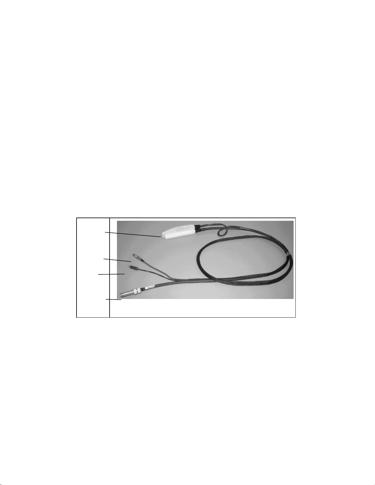
A-Handpiece Control Connector
B-Cryogen Output Connector
C-Fiber Proximal End (should be blue)
D-Glass Windows
E-Distance Gauge
F-O Ring
E D F
Figure 2. Distance Gauge
5. Distance Gauge Installation:
5.1. Refer to figure 1above for distance gauge location.
Note: The distance gauge must be removed before performing the calibration
procedure.
5.2. Insert the distance gauge into the distal end of the handpiece delivery
system.
6. Footswitch Installation:
6.1. Remove the footswitch from its package.
6.2. Attach the tubing end to the bulkhead connector on the rear panel of the
laser.
7. COMPLETETHE DATA SHEET, 10-400-00145,PER THE CALIBRATION AND
VERIFICATION DATA SHEET, 8503-01-0832.
8. Relocation:
8.1. Care should always be taken when moving the GentleYAG.The system was
designed to be moved, but special care should be taken when thresholds,
elevator doors, ramps, and other uneven or sloping floor surfaces are
encountered. A severe physical shock could cause the alignment of the
laser head or the optical fiber to be disturbed. Furthermore, if the system is
allowed to get out of control when being moved, personal injury or physical
damage could result.
8.2. If it becomes necessary to relocate the GentleYAG, call Candela or the
distributor for details. Failure to do so may result in damage to the system,
and may void any warranty.