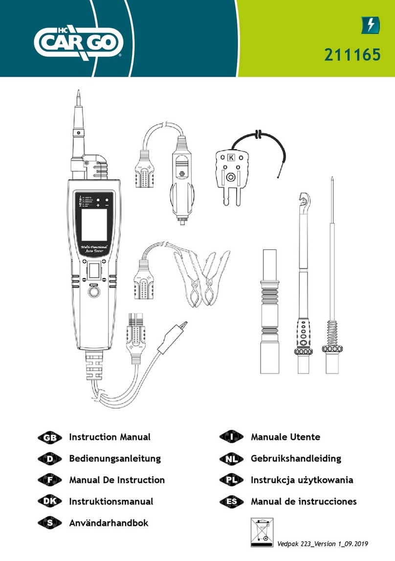
Cargo 211097 User manual

1Vedpak 132_501186_Version 4_12.2017
STRØMTESTER
Brugsanvisning
Vedpak 132_501186_Version 4_12.2017
TESTEUR / VOLTMETRE
MANUEL D’UTILISATION
CIRCUIT TESTER
USER MANUAL
211097

2Vedpak 132_501186_Version 4_12.2017
211097
INTRODUCTION
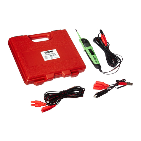
The HC-CARGO 211097 is the most revolutionary circuit
tester to date. The HC-CARGO 211097 literally speeds
you through the diagnosing of 12 to 24 volt automotive
electrical systems. After connecting the HC-CARGO
211097’s clips to the vehicle’s battery the automotive
technician can determine at a glance, the voltage level
and the polarity of a circuit without running for a voltme-
ter or reconnecting hook-up clips from one battery pole
to the other. The power switch allows the automotive
technician to conduct a positive or negative battery
current to the tip for activating and testing the function of
electrical components without wasting time with jumper
leads. And the HC-CARGO 211097 is short circuit pro-
tected. It tests for bad ground contacts instantly without
performing voltage drop tests. It allows you to follow and
locate short circuits without wasting precious fuses. The
HC-CARGO 211097 can also test for continuity with the
assistance of its auxiliary ground lead. With a ip of the
power switch, you will know at a glance that your HC-
CARGO 211097 is functionning without running to the
battery as you would otherwise have to do with simple
test lights. The HC-CARGO 211097’s long cable allows
you to test along the entire length of the vehicle without
constantly searching for ground hook-ups. An absolute
must for every automotive
technician looking for a fast and accurate solution to
electrical systems diagnostics.
Before using the tester please read the instruction book
carefully.
WARNING
When the testers switch is depressed battery current/
voltage is conducted directly to the tip which may cause
sparks when contacting ground or certain circuits.
Therefore the tester should NOT be used around
ammables such as gasoline or its vapors. The spark
of an energized HC-CARGO 211083 could ignite these
vapors.
Use the same caution as you would when using an arc
welder.
HC-CARGO 211097 is NOT to be used with 110/220
volt home electrical, it is only for use with 12-24 volt
systems.
Table of Contents
HC-CARGO 211097 instructions...........................................................................................1
Hook-up and quick self-test ..................................................................................................2
Turning the audio tone on and o .........................................................................................2
Circuit breaker.......................................................................................................................3
Voltage and polarity testing...................................................................................................3
Continuity testing ..................................................................................................................4
Activating components out of vehicle’s electrical system .....................................................5
Testing trailer lights and connections....................................................................................6
Activating electrical components in the vehicle.....................................................................7
Activating electrical components with Ground ......................................................................8
Checking for bad ground contact..........................................................................................9
Following and locating short circuits .....................................................................................9
Red/Green polarity indicator and audio tone ........................................................................9
Modes ...................................................................................................................................9
Modes chart ........................................................................................................................11
IMPORTANT TIP:
When powering-up components, you can increase the life of your
HC-CARGO 211097 switch, if you rst press the switch, then contact the tip
to the component. The arcing will take place at the tip instead of the
contacts of the switch.

3Vedpak 132_501186_Version 4_12.2017
211097
HOOK-UP
Unroll the cable.
Connect the RED battery hook-up clip to the POSITIVE
(+) terminal of the vehicle’s battery.
Connect the BLACK battery hook-up clip to the
NEGATIVE (÷) terminal of the vehicle’s battery.
When the tester is rst connected to a battery (power
source), it will sound a quick high and then low beep and
go into “Power Probe Mode“ (See Mode #1 on page 9)
and the 2 bright white LEDs 8dual head lights9 will be on
to illuminate the test area of the probe tip.
QUICK SELF-TEST
While the tester is in Power Probe Mode, press the po-
wer switch forward to activate the tip with a positive (+)
voltage. The positive sign (+) LED should light red and
the LCD display will read the battery (supply) voltage.
If the tone feature is turned on, a high pitched tone will
sound.
Press the power switch rearward to activate the tip with
a negative (÷) voltage. The negative sign (÷) LED should
light green and the LCD display will read “0.0“ (ground).
If the tone feature is turned on, a low pitched tone will
sound. The tester is now ready to use. If the indicator did
not light, depress the reset button of the circuit breaker
on the right side of the housing and try the selftest again.
TURNING THE AUDIO TONE ON AND OFF
While the tester is in Power Probe Mode, just do a quick
press of the mode button to toggle the tone on or o.
While quickly pressing (a quick press and release) the
mode button, if a short high beep is heard, this means
the audio tone is turned on. If a short low beep is heard,
the audio tone is o.

4Vedpak 132_501186_Version 4_12.2017
211097
CIRCUIT BREAKER
In Power Probe Mode (Mode#1) with the circuit breaker
tripped, the LCD will display the symbol
“C B“ (see page 11 for detail). All other functions of the
HC-CARGO 211097 are still active. This means that you
can still probe a circuit and observe the voltage reading.
When the circuit breaker is tripped, the HC-CARGO
211097 will NOT be able to conduct battery current to
the tip even when the power switch is pressed. Inten-
tionally tripping the breaker and using the HC-CARGO
211097 to probe can be considered an added precaution
against accidental pressing of the power switch.
VOLTAGE AND POLARITY TESTING
While the HC-CARGO 211097 is in Power Probe Mode,
contact the probe tip to a POSITIVE circuit. The red
positive sign “+“ LED will light and the voltmeter displays
the voltage reading within 1/10th of a volt (0.1 V.).
If the audio feature is turned on, a high pitched tone will
sound. (See RED/GREEN POLARITY INDICATOR AND
AUDIO TONE on page 9).
While the HC-CARGO 211097 is in Power Probe Mode,
contact the probe tip to a NEGATIVE circuit. The green
negative sign “÷“ LED will light and the voltmeter
displays the voltage. If the audio feature is turned on, a
low pitched tone will sound.
Contacting the Power Probe tip to an OPEN circuit will
be indicated by neither of the LED indicators lighting.
While the HC-CARGO 211097 is in Power Probe Mode, con-
tact the probe tip to a POSITIVE circuit. The red positive sign
“+“ LED will light and the voltage reading of the circuit will be
indicated on the LCD display. If the audio feature is turned
on, a high pitched tone will sound.
While the HC-CARGO 211097 is in Power Probe Mode, con-
tact the probe tip to a NEGATIVE circuit. The green negative
sign “÷“ LED will light. If the audio feature is turned on, a low
pitched tone will sound.

5Vedpak 132_501186_Version 4_12.2017
211097
CONTINUITY TESTING
While the HC-CARGO 211097 is in Power Probe Mode,
and by using the Power Probe tip in connection with the
auxiliary ground lead, continuity can be tested on
wires and components that are disconnected from the
vehicle’s electrical system.
When continuity is present, the green negative sign “÷“
LED will light and the LCD display should indicate “0.0“
volts.
No continuity
Green = Continuity
Continuity

6Vedpak 132_501186_Version 4_12.2017
211097
ACTIVATING COMPONENTS OUT OF VEHICLE’S ELEC-
TRICAL SYSTEM
While the HC-CARGO 211097 is in Power Probe Mode
and by using the Power Probe tip in connection with the
auxiliary ground lead, components can be activated right
on your hand, thereby testing their function.
Connect the negative auxiliary clip to the negative
terminal or ground side of the component being tested.
Contact the probe to the positive terminal of the
component, the green negative sign “÷“ LED indicator
should light GREEN indicating continnuity through the
component.
While keeping an eye on the green LED negative sign,
quickly depress and release the power switch forward
(+). If the green negative sign “÷“ LED went out and the
red positive sign “+“ came on, you may proceed with
further activation. If the green negative sign “÷“ LED
went o at that instant or if the circuit breaker tripped,
the Power Probe has been overloaded.
This could happen for the following reasins:
• The contact you are probing is a direct ground or
negative voltage.
• The component you are testing is short-circuited.
• The component is a high current component
(i.e., starter motor).
If the circuit breaker is tripped, reset it by waiting for it to
cool down and then depressing the reset button.
Connect the
negative auxiliary
clip
Connect the tip to
the positive terminal
of the bulb
Press the power
switch forward to activate
the bulb
Activate fuel pumps, magne-
tic clutches, starter solenoids,
cooling fans, blower motors,
lights etc.

7Vedpak 132_501186_Version 4_12.2017
211097
TESTING TRAILER LIGHTS AND CONNECTIONS
1. Connect the tester to a good battery.
2. Clip the auxiliary ground clip to the trailer ground.
3. Probe the contacts at the jack and apply voltage to
them. This lets you check the function and orientation
of the connector and trailer lights. If the circuit
breaker tripped, that contact is likely a ground.
Reset the circuit breaker by letting it cool down and
depressing the reset button until it clicks into place.
ACTIVATING ELECTRICAL COMPONENTS
IN THE VEHICLE
To activate components with positive (+) voltage:
Contact the probe tip to the positive terminal of the
component, the green negative sign “÷“ LED should light.
Indicating continuity to ground.
While observing the green indicator, quickly depress
and release the power switch forward (+). If the green
indicator went out and the red positive sign (+) LED came
on, you may proceed with further activation. If the green
indicator went o at that instant or if the circuit breaker
tripped, the tester has been overloaded. This could hap-
pen for the following reasons:
• The contact is a direct ground.
• The component is short-circuited.
• The component is a high current component
(i.e., starter motor).
If the circuit breaker tripped, reset it by allowing it to cool
down and then depress the reset button.
WARNING: Haphazardly applying voltage to certain
circuits can cause damage to a vehicle’s electronic
components. Therefore, it is strongly advised to use
the correct schematic and diagnosing procedure while
testing.
Trick: When powering-up compo-
nents, you can increase the life of
your tester switch if you rst press
the switch, then contact the tip to the
component. The arcing will take place
at the tip instead of the contacts of
the switch.

8Vedpak 132_501186_Version 4_12.2017
211097
ACTIVATING ELECTRICAL COMPONENTS
WITH GROUND
Contact the probe tip to the negative terminal of the
component, the LED indicator should light RED.
While keeping an eye on the red positive sign “+“ LED,
quickly depress and release the power switch rearward
(-). If the red indicator went out and the green negative
sign (÷) came on you may proceed with further activation.
If the green indicator went o at that instant or if the
circuit breaker tripped, the tester has been overloaded.
This could have happened for the following reasons:
• The contact is a direct positive voltage.
• The component is short-circuited.
• The component is a high current component
(i.e., starter motor).
If the circuit breaker tripped, reset it by allowing it to cool
down and then depress the reset button.
WARNING: With this function, if you are contacting a
protected circuit, a vehicle’s fuse can be blown or tripped
if you apply ground to it.
Depress the rocker switch
rearward to ground the horn
Horn
Fuse box

9Vedpak 132_501186_Version 4_12.2017
211097
CHECKING FOR BAD GROUND CONTACT
Probe the suspected ground wire or contact with the
probe tip.
Observe the green negative sign “÷“ LED. Depress the
power switch forward then release. If the green negative
sign “÷“ LED went out and the red positive sign “+“ came
on, this is not a true ground. If the circuit breaker
tripped, this circuit is more than likely a good ground.
Keep in mind that high current components such as
starter motors will also trip the circuit breaker.
FOLLOWING AND LOCATING SHORT CIRCUITS
In most cases a short circuit will appear by a fuse or a
fusible link blowing or an electrical protection device
tripping (i.e., a circuit breaker). This is the best place to
begin the dearch. Remove the blown fuse from the fuse
box.
Use the Power Probe tip to activate and energize each
of the fuse contacts. The contact which trips the HC-
CARGO 211097 circuit breaker is the shorted circuit.
Take note of this wire’s identication code or color. Fol-
low the wire as far as you can along the wiring harness,
for instance if you are following a short in the brake light
circuit you may know that the wire must pass though the
wiring harness at the door sill. Locate the color-coded
wire in the harness and expose it. Probe through the in-
sulation with the Power Probe tip and depress the power
switch forward to actovate and energize the wire. If the
Power Probe circuit breaker tripped you have veried
the shorted wire. Cut the wire and energize each end
with the Power Probe tip. The wire end which trips the
Power Probe circuit breaker again is the shorted circuit
and will lead you to the shorted area. Follow the wire in
the shorted direction and repeat this process until the
short is located.
RED/GREEN POLARITY INDICATOR AND
AUDIO TONE
The “RED/GREEN Polarity Indicator“ lights-up when the
probe tip voltage matches the battery voltage within ±
0.5 V. This means that if you contact a circuit that is not
a good ground or a good hot, you will see this instantly
by the “RED/GREEN Polarity Indicator“ NOT lighting.
The Audio Tone runs parallel to the “RED/GREEN Pola-
rity Indicator“ and will also NOT react when contacting
a circuit that does not match the battery voltage within
± 0.5 V.
MODES
Using the advanced features and modes is optional.
However, understanding them will expand your
diagnosing capabilities. The LCD display indicates
voltage levels of the circuit along with an identifying
symbol showing what mode it is in. the additional
features contain 5 modes which gives specic
information about how the circuit is reacting. The 5 mo-
des can be accessed by depressing the MODE button
and through each one.
Mode #1 Power Probe Mode:
While the HC-CARGO 211097 is in “Power Probe Mode“
and the probe tip is oating (not contacting a circuit), the
LCD backlight is on but the display is blank. If the audio
tone is turned on you will see a speaker symbol in the
lower right corner of the display.
Once you contact the probe tip to a circuit the LCD
display will indicate the average voltage level of the
circuit. The red/green polarity indicator (See section
Red/Green Polarity Indicator and Audio Tone) will
respond also, showing whether the circuit is positive or
negative.
A secondary feature in this mode is the peak threshold
detection and signal monitoring. When contacting a
signal generating circuit such as a speaker wire with
audio signals on it, the HC-CARGO 211097 detects
the peak to peak signals and displays the peak to peak
voltage in the display, the sound of the signals will be
monitored and heard through the HC-CARGO 211097
speaker. The peak to peak threshold levels are pre-
selected by the operator in “Mode 5“. See Mode #5 for
more information on
setting threshold levels.
Placing the HC-CARGO 211097 tip next to a sparkplug
wire (NOT probing directly), allows you to monitor the
sound of the ignition pulses at the same time display a
peak to peak reading. The HC-CARGO 211097 senses
the pulses in ignition wires through capacitive coupling
(DO NOT CONTACT PROBE TIP DIRECTLY TO THE
SECONDARY IGNITION CIRCUIT). By monitoring each
plug wire in this way you can locate missing cylinders.
Mode #2 Negative Peak Mode:
The Negative Peak Mode monitors a positive circuit
and captures the lowest voltage that it has dropped to.
To do this: Place the HC-CARGO 211097 in “Negative
Peak Mode“ by pressing and holding the mode button
for 1 second until you hear a low pitched beep and the
LCD display indicates a negative (÷) sign in the lower
left corner. The display should also indicate a reading
of “0.0“ with the probe oating. (This is because no
voltage is present). Probe the positive circuit you want
to test and tap the mode button once. The LCD display
will show the lowest detected voltage of the circuit. If the
circuit drops in
voltage at anytime, a new lowest reading will be
captured and displayed. You can then do a quick tap of
the mode button once again to reset the LCD display
and indicate the new voltage level on the circuit. Reset
the LCD display by doing a quick tap of the mode button
as often as necessary.
An APPLICATION for the use of the “Negative Peak
Mode“: Lets say you have a circuit that is suspect of
10 Vedpak 132_501186_Version 4_12.2017
211097
loosing a connection and the voltage drops, causing
something to turn o or malfunction. Probing the circuit
and monitoring it in “Negative Peak Mode“ will instantly
indicate as the circuit drops in voltage. You can monitor
the circuit while wiggling wires and pulling on connectors
to see if the voltage drops. Since the minimum voltage
reading is captured and held on the display, you can
inspect it at a later time. You could also perform a bat-
tery crank test.
Mode #3 Positive Peak Mode:
The “Positive Peak Mode“, monitors the probed circuit
and captures the highest detected voltage. Place the
HC-CARGO 211097 into “Positive peak Mode“ by pres-
sing and holding the mode button for 1 second until you
hear a beep. Repeat this until you hear a quick high pit-
ched beep and the LCD display indicates a positive (+)
sign in the lower left corner. The display should also indi-
cate a reading of “0.0“ with the probe tip oating. Probe
the circuit and the HC-CARGO 211097 instantly displays
and holds the highest voltage reading. This means you
can remove the probe from the circuit and the voltage
reading remains displayed for your reference. Reset the
LCD display by doing a quick tap of the mode button.
An APPLICATION for the use of the “Positive Peak
Mode“: Lets say you have a circuit that is supposed to
be o and it is suspected of turning on inappropriately or
getting a signal for some reason. Probing the circuit and
monitoring it in the “Positive Peak Mode“ will instantly
indicate as the circuit increases in voltage. You can
monitor the circuit while wiggling wires and pulling on
connectors to see if the voltage increases. Since the
maximum voltage reading is captured and held on the
display, you can inspect the reading at a later time.
Maybe you have to probe a circuit deep under a dash
and the display is obstructed from view. In “Positive
Peak Mode“ just probe the wire then remove the probe
and look at your voltage reading. Connect to starter
terminal to capture maximum voltage to the starter while
cranking. Quickly nds voltage drops in the wiring and
start connection (Soledoid).
Mode #4 Peak to Peak Mode:
The “Peak to Peak“ mode measures the dierence
between the positive and negative peak voltage levels
over a 1 second period. With this feature you can
measure and monitor for example, the diode rectier in
a charging system while the engine is running. The peak
to peak readings will give the technician the data
necessarry to determine if a diode rectier is defective
or not. A normal peak to peak reading while testing a
charging circuit is usually under 1 volt. If a defective
rectier is present the peak to peak reading will be over
1 volt and possibly over 3 volts.
When probing in “Peak to Peak Mode“ the display
shows activity of circuits such as fuel injectors, distri-
butor pick-ups, cam and crank sensors, oxygen sensors,
hall eect sensors. Measures yback voltage of injectors
to quickly nd a problem.
Mode #5 Treshold Level Setting for the Peak to Peak
Detection in Power Probe Mode:
This mode is only used to adjust the treshold voltage
in “Power Probe Mode“ for peak to Peak Detection and
Signal Monitoring. To set the threshold level for the peak
to peak detection in “Power Probe Mode“, press and
hold the mode button for one second until you hear the
beep. Repeat this a second, third and fourth time and/or
until an alternating positive (+) and negative (÷) sign is
present in the bottom left corner of the LCD display. You
can now toggle the threshold level by a quick tap of the
mode button and observing the voltage level settings.
The peak to peak threshold voltage settings loop
incrementally from 0.2, to 0.5 to 1.0 to 2.0 to 5.0 to 10.0
to 50.0 and return back to 0.2 again. An audio installer
would nd the 0.2 V. setting convenient.
Once you select the desired threshold voltage, press
and hold the mode button again until it beeps. This
returns you to the “Power Probe Mode“. You will know
that you are in the “Power Probe Mode“ when the LCD
display is blank and/or with the “Speaker Symbol“ shown
in the bottom right corner.

11 Vedpak 132_501186_Version 4_12.2017
211097
Navigation Mode# Display Mode/Function Output
When the HC-CARGO
211097 is initially con-
nected to the vehicles
battery or a 12-24 volt
power supply, it enters
Mode#1
automatically.
To enter into Mode#2
press and hold Mode
button until you hear a
low pitched beep.
To enter into Mode#3
press and hold Mode
button until you hear a
high pitched beep.
To enter into Mode#4
press and hold Mode
button until you hear a
low to high pitched beep.
To enter into Mode#5
press and hold Mode
button until you hear a
mid pitched beep.
To return to Mode#1
press and hold Mode
button until you hear a
high and low beep.
#1
#2
#3
#4
#5
Power Probe Mode:
With Audio Tone On.
Power Probe Mode:
With Audio Tone O.
Power Probe Mode:
With the Circuit
Breaker tripped with
Audio Tone On.
Power Probe Mode:
with the Circuit
Breaker tripped with
Audio Tone O
Negative Peak to
Peak Mode
Positive Peak to
Peak Mode
Peak to Peak Mode
Peak to Peak
Threshold Setting
Mode: Detects Peak
to Peak in Power
Probe Mode.
Displays the average
D.C. voltage.
Displays the Peak
to Peak A.C. voltage
when the voltage is
more than Mode 5
Threshold setting.
Limited to 65 V.
Captures the most
negative voltage
transition.
Captures the most
Positive voltage
transition.
Displays the
dierence between
Peak to Peak
voltage.
Sets the Peak to
Peak Threshold
Level for the
Mode#1 display to
transition from D.C.
to A.C.
Actively alterna-
ting + to ÷ to +,
etc.

12 Vedpak 132_501186_Version 4_12.2017
211097
INTRODUKTION
Denne strømtester er den mest revolutionerende strøm-
kredstester til dato. HC-CARGO 211097 speeder dig i
bogstaveligste forstand gennem diagnosticeringen af
12 til 24 volt elektriske systemer. Efter at have tilsluttet
strømtesterens klemmer med køretøjets batteri, kan
automekanikeren med det samme fastsætte spændings-
niveauet og strømkredsløbets polaritet uden at behøve
at skulle løbe efter et voltmeter. Afbryderen gør det
muligt for automekanikeren at lede en positiv eller nega-
tiv batteristrøm til spidsen for aktivering og test af elektri-
ske komponenter. Denne strømtester er beskyttet imod
kortslutninger. Testeren kontrollerer med det samme, om
der er dårlige stelforbindelser tilstede uden at behøve
at skulle foretage nogen spændingsfaldstest. Du har
mulighed for at følge og lokalisere kortslutninger uden at
ødelægge kostbare sikringer. Strømtesteren tester også
strømgennemgangen med hjælp fra testerens ekstra
jordledning. Med et knips på afbryderen vil du med det
samme være i stand til at fastslå, om din tester virker,
uden at behøve at skulle gå hen til batteriet som du
ellers ville have været nødt til at gøre med almindelige
prøvelamper. Testapparatets lange kabel gør det muligt
for dig at udføre dine test langs med hele bilens længde
uden hele tiden at behøve at skulle lede efter stelforbin-
delser. Et absolut must for enhver automekaniker, som
leder efter en hurtig og præcis løsning på diagnosticerin-
gen af de elektriske systemer.
Før ibrugtagning anbefales det at læse denne instruk-
wtionsbog grundigt igennem.
ADVARSEL
Når testerens kontakt er trykket ned ledes batteristrøm-
men/spændingen direkte til spidsen, hvilket kan medføre
gnister ved berøring med stelkredsløb eller særlige
kredsløb. Undgå derfor at bruge testapparatet i og om-
kring brandfarlige ting så som benzin eller dampe herfra.
En gnist fra et aktivt testapparat kan antænde disse
dampe. Udvis samme forsigtighed som ved brugen af
en lysbuesvejser.
HC-CARGO 211097 MÅ IKKE bruges med 110/220 volt
husholdningsstrøm, men må kun bruges sammen med
12-24 volt systemer.
Indholdsfortegnelse
HC-CARGO 211097 instruktioner ..................................................................................1
Tilslutning og hurtig selvtest ...........................................................................................2
Tænd og sluk for lyden...................................................................................................2
Afbryder..........................................................................................................................3
Spændings- og polaritetstest..........................................................................................3
Test af strømgennemgang..............................................................................................4
Aktivering af dele i hånden.............................................................................................5
Test af anhængerlys og forbindelser ..............................................................................6
Aktivering af elektriske dele inde i køretøjet...................................................................7
Aktivering af elektriske dele ved hjælp af stelforbindelse...............................................8
Kontrol af dårlige stelforbindelser...................................................................................9
Følge og lokalisering af kortslutning...............................................................................9
Rød/grøn indikator & lydtone..........................................................................................9
Funktioner ......................................................................................................................9
Funktions diagram........................................................................................................11
VIGTIG INFORMATION:
Du kan forlænge strømtesterens levetid ved først at trykke på
kontakten og derefter aktivere komponenten med spidsen.

13 Vedpak 132_501186_Version 4_12.2017
211097
TILSLUTNING
Rul kablet ud.
Den røde batteriklemme forbindes med + polen på
køretøjets batteri.
Den sorte batteriklemme forbindes med – polen på
køretøjets batteri.
Når testeren er forbundet med et batteri (strømforsy-
ning), vil der først lyde en hurtig høj og bagefter en dyb
biplyd og testeren går over i ”funktion for test af strøm”
(se funktionsbeskrivelse #1 på side 12) og de to klare
lysdioder ude foran på testeren (dobbelte ”forlygter”)
tændes.
HURTIG SELVTEST
Pres afbryderen fremad for aktivering af spidsen med
en positiv (+) spænding. Plusdioden lyser rød og LCD-
skærmen aæser batterispændingen. Er lydfunktionen
slået til, vil man kunne høre en høj tone.
Pres afbryderen bagud for aktivering af spidsen med en
negativ spænding. Den negative (-) lysdiode lyser grøn
og i LCD-skærmen aæses tallene ”0,0” (stel). Er lyd-
funktionen slået til, vil man kunne høre en lav tone.
Nu kan strømtesteren bruges. Hvis måleapparatet ikke
lyser, tryk på reset-kontakten på højre side af kabinettet
og kør selvtesten en gang til.
TÆND OG SLUK AF LYD
Tryk ganske let på funktionsknappen for tænd og sluk
af lyd. Hvis der i forbindelse med et hurtigt tryk på
funktionsknappen (hurtig tryk og slip) høres en kort men
høj biplyd betyder det, at lyden er slået til. Hvis der høres
en kort men dyb biplyd er lydfunktionen slået fra.

14 Vedpak 132_501186_Version 4_12.2017
211097
AFBRYDER
Med afbryderen slået fra vil LCD-skærmen vise
symbolet ”C B” (for yderligere information se s. 13). Alle
øvrige funktioner på testapparatet er stadigvæk aktive.
Du kan således stadigvæk teste kredsløbet og aæse
spændingen. Når kontakten er slået fra, vil strømteste-
ren ikke være i stand til at lede batteristrømmen op til
spidsen selv med kontakten trykket ned. Bevidst udløs-
ning af kontakten og brug af strømtesteren anses for en
yderligere forholdsregel mod tilfældigt tryk på kontakten.
TEST AF SPÆNDING OG POLARITET
Forbind prøvespidsen med et positivt kredsløb.
Den røde positive ”+” LED lyser og voltmeteret viser
spændingen med en 1/10 volts nøjagtighed (0,1 v).
Hvis lydfunktionen er slået til, høres der en høj biplyd
(se rød/grøn polaritetsindikator og lyd på s. 11).
Forbind prøvespidsen med et negativt kredsløb.
Den grønne negative ”-” LED lyser og voltmeteret
angiver spændingen. Hvis lydfunktionen er slået til,
høres der en lav biplyd.
Hvis strømtesteren kommer i kontakt med et ÅBENT
kredsløb vil ingen af LED-indikatorerne lyse.
I strømtestfunktion bringes prøvespidsen
i kontakt med et POSITIVT kredsløb. Herved lyser
den røde positive ”+” LED og kredsløbets
spænding aæses på LCD-skærmen.
Hvis lydfunktionen er slået til, høres der en høj biplyd.
I strømtestfunktion bringes prøvespidsen
i kontakt med et NEGATIVT kredsløb. Herved lyser
den grønne negative ”-” LED.
Hvis lydfunktionen er slået til, høres der en lav biplyd.

15 Vedpak 132_501186_Version 4_12.2017
211097
TEST AF STRØMGENNEMGANG
Ved at bruge prøvespidsen i forbindelse med ekstern
stelforbindelse, kan man teste strømgennemgangen på
ledninger og dele, som er blevet koblet fra køretøjets
elektriske system.
Ved strømgennemgang lyser den grønne ”-” LED og
LCD-skærmen viser ”0,0” volt.
Ingen strømgennemgang
Grøn = Strømgennemgang
Strømgennemgang

16 Vedpak 132_501186_Version 4_12.2017
211097
AKTIVERING AF DELE I HÅNDEN
Ved at bruge prøvespidsen i forbindelse med ekstern
stelforbindelse, har man mulighed for at aktivere delene
direkte i ens hånd og derved teste delenes funktion.
Forbind den negative eksterne klemme med den nega-
tive pol eller med grundsiden af den del, der skal testes.
Spidsen bringes i forbindelse med delens positive
klemme. Herved bør den grønne ”-” LED lyse op som in-
dikation for, at der er strømgennemgang gennem delen.
Hold øje med den grønne ”-” LED, tryk hurtig ned på
kontakten og skub kontakten frem (+).Hvis den grønne
negative ”-” LED går ud og den røde ”+” LED tænder,
fortsættes med aktiveringen. Hvis den grønne ”-” LED
går ud eller hvis kontakten slår fra, er strømtesteren
blevet overbelastet. Det kan ske af følgende årsager:
• Forbindelsen der testes er en direkte stelforbindelse
eller en negativ spænding.
• Delen der testes, er kortsluttet.
• Der er tale om en enhed med høj strømstyrke
(dvs. en startmotor).
Hvis kontakten er slået fra, nulstilles den igen idet man
venter på at den afkøles. Tryk derefter på nulstillings-
knappen.
Den negative
hjælpeklemme
tilsluttes
Spidsen forbindes med
pærens positive pol
Tryk kontakten
fremad for at
aktivere pæren
Aktiverer benzin pumper,
magnetkoblinger, startrelæer,
ventilatorer, blæsemotorer,
lys etc.

17 Vedpak 132_501186_Version 4_12.2017
211097
TEST AF ANHÆNGERLYS OG FORBINDELSER
1. Strømtesteren forbindes med et godt batteri
2. Den eksterne klemme spændes fast til
anhængerens stelforbindelse
3. Afprøv kontakterne ved bøsningen og sæt strøm til.
Herved får man mulighed for at kontrollere funktion
og retning på bøsningen og anhængerlys. Hvis
afbryderen slår fra, er der højst sandsynlig tale om
en stelforbindelse. Nulstil afbryderen ved at lade den
køle ned og tryk på nulstillingsknappen indtil afbryde-
ren klikkes på plads.
AKTIVERING AF ELEKTRISKE DELE I KØRETØJET
Aktivering af komponenter med positiv (+) spænding:
Forbind prøvespidsen med komponentens positive pol;
den grønne (-) LED lyser. Angiver strømgennemgang til
stel.
Medens der holdes øje med den grønne måler, tryk hurtig
på kontakten og skub den fremad (+). Går den grønne
indikator ud og den røde LED tændes, fortsættes med
aktiveringen. Går den grønne ”-” LED ud eller slår afbry-
deren fra, er testeren blevet overbelastet. Det kan ske af
følgende årsager:
• Forbindelsen er en direkte stelforbindelse.
• Enheden er kortsluttet.
• Der er tale om en enhed med høj strømstyrke
(d.v.s. en startmotor).
Slå afbryderen fra, afkøl testeren og tryk på nulstillings-
knappen.
ADVARSEL: Vilkårlig tilførsel af spænding til visse kreds-
løb kan skade køretøjets elektroniske komponenter/
enheder. Det anbefales at bruge bilfabrikantens skemaer
og fejlndingsprocedure under testen.
FIF: Ved strømtilførsel til kompo-
nenterne kan man forlænge livet for
knappen på testapparatet ved først at
trykke på kontakten og efterfølgende
bringe spidsen i berøring med enhe-
den. Lysbuedannelsen vil ske ved
spidsen i stedet for ved kontaktens
forbindelser.

18 Vedpak 132_501186_Version 4_12.2017
211097
AKTIVERING AF ELEKTRISKE DELE
VED HJÆLP AF STELFORBINDELSE
Prøvespidsen bringes i kontakt med enhedens negative
pol. ”+” LEDen lyser rød.
Hold øje med det røde ”+” LED lys. Tryk hurtig på strøm-
afbryderen og sæt den på (-). Går det røde ”+” lys ud og
tændes det grønne lys (-) fortsæt med aktiveringen. Går
det grønne ”-” lys ud eller slår afbryderen fra, er testeren
blevet overbelastet. Der kan ske af følgende årsager:
• Forbindelsen er en direkte stelforbindelse
• Enheden er kortsluttet
• Der er tale om en enhed med høj strømstyrke
(dvs. startmotor)
Slå afbryderen fra, afkøl testeren og tryk på nulstillings-
knappen.
ADVARSEL: Med denne funktion kan køretøjets sikring,
hvis man er i kontakt med et beskyttet kredsløb, spræn-
ges, hvis jord tilføjes.
Tryk vippekontakten
bagud for at sætte
stel til hornet
Horn
Sikringsdåse

19 Vedpak 132_501186_Version 4_12.2017
211097
KONTROL AF DÅRLIGE STELFORBINDELSER
Den mistænkte stelledning eller forbindelse undersøges
med prøvespidsen.
Hold øje med den grønne ”–” LED. Tryk afbryderen frem
og slip. Går den grønne ”-” LED ud og tændes den røde
”+” LED, er der ikke tale om en ægte stelforbindelse.
Slår afbryderen fra, er der tale om et kredsløb med god
stelforbindelse. Husk på at enheder med stort strømfor-
brug så som startmotorer også vil slå afbryderen fra.
FØLG OG LOKALISER KORTSLUTNINGER
Kortslutninger sker i de este tilfælde på grund af at en
sikring eller et smelteled springes, eller ved at en elek-
trisk beskyttelsesindretning slår fra (dvs. en afbryder).
Dette er det bedste sted at påbegynde sin søgning. Den
sprængte sikring fjernes fra sikringsdåsen.
Brug prøvespidsen til at aktivere og sende strøm gen-
nem hver sikringsforbindelse. Forbindelsen der slår
afbryderen fra er lig med det kortsluttede kredsløb.
Bemærk ledningens identikationskode eller farve. Følg
ledningen så langt du kan langs ledningsnettet. Følger
man f.eks. en kortslutning i bremselygtekredsløbet ved
man, at ledningen gennemløber ledningsnettet ved dør-
trinnet. Find den farvekodede ledning i ledningsnettet og
blotlæg den. Ved hjælp af spidsen undersøges lednin-
gen igennem isoleringen og der trykkes på afbryderen
for at aktivere og sætte strøm gennem ledningen. Slår
afbryderen fra, bekræftes den kortsluttede ledning. Klip
ledningen over og sæt strøm igennem hver ende. Den
ledningsende, der slår afbryderen på testapparatet fra,
er den kortsluttede ledning og vil føre dig til det kortslut-
tede område. Følg ledningen i den kortsluttede retning
og gentag processen indtil kortslutningen er fundet.
RØD/GRØN POLVISER OG LYD
Den rød/grønne polviser tænder, når prøvespidsens
spænding matcher batterispændingen inden for en
ramme på ± 0,5 volt. Det betyder at man, hvis man be-
rører en dårlig stelforbindelse eller en god strømførende
forbindelse, med det samme vil kunne se det på den
rød/grøn polviser ved, at den IKKE LYSER. Lyden løber
parallelt med rød/grøn polviseren og vil IKKE reagere,
hvis man kommer i berøring med et kredsløb, som ikke
matcher batterispændingen indenfor en ramme på ±
0.5 volt.
FUNKTIONER
Denne tester er designet til at kunne fungere på samme
måde, som de andre strømtestere. Brugen af de
avancerede features og funktioner er valgfri. Men en
forståelse herfor vil udvide ens muligheder for fejlnding.
LCD-skærmen angiver kredsløbets spændingsniveauer
sammen med et identikationssymbol, som angiver i
hvilken funktion man er i. Denne nye feature indeholder
5 nye funktioner, som vil forsyne en med særlige oplys-
ninger om, hvordan kredsløbet reagerer. Tryk på funkti-
onsknappen og gennemgå hver af de 5 funktioner.
Funktion #1, strømtest:
Når testeren bender sig i strømtestfunktion og prøve-
spidsen føres henover et kredsløb(ingen berøring med
kredsløb), vil baggrundslyset i LCD-skærmen være
tændt, mens displayet vil være tomt. Hvis lyden er slut-
tet til, ses et højtalersymbol i nederste højre hjørne af
displayet.
Ved berøring med et kredsløb vil LCD-skærmen vise
kredsløbets gennemsnitlige spændingsniveau. Den rød/
grønne polviser (se afsnit om rød/grøn polviser og lyd)
vil også reagere og vise om kredsløbet er negativt eller
positivt.
En anden feature i denne funktion er spids-til-spids
visning og signalovervågning. Ved berøring med et
signalgenererende kredsløb som for eksempel en
højtalerledning med lydsignaler, vil testeren vise spids-
til-spidssignalerne og vise spids-til-spidsspændingen på
displayet. Lyden fra signalerne vil blive overvåget og vil
kunne høres igennem testerens højtaler. Disse spids-
til-spidsvisninger er blevet forudindstillet af operatøren i
”funktion 5”. Se beskrivelse for funktion 5 for yderligere
informationer vedr. indstilling af tærkselniveauer.
Placer prøvespidsen ved siden af tændrørsledningen
(må IKKE testes direkte). Herved får man mulighed for,
at overvåge lyden fra tændingsimpulserne samtidig med
at spids-til-spidsaæsningen vises. Testeren aøser
impulserne i tændkablerne gennem kapacitiv kobling
(Lad ikke spidsen komme i direkte berøring med den
sekundære tændingskreds).
Ved at overvåge hver enkel tændrørsledning har man
mulighed for at nde de manglende cylindere.
Funktion #2, negativ spidsværdivisning:
Denne funktion overvåger det positive kredsløb og
opfanger den underspænding som kredsløbet falder til.
Indstil testeren til negativ spidsvisnings idet der trykkes
og holdes på funktionsknappen i et sekund, indtil der
høres en lav stigende biplyd og LCD-skærmen viser
et negativt tegn i nederste venstre hjørne. Displayet
viser en aæsning på 0,0 med prøvespidsen svævende
henover (grunden hertil er, at der ikke er nogen spæn-
ding tilstede). Undersøg det positive kredsløb og tryk
ganske let på knappen. LCD-skærmen viser kredsløbets
lavest fundne spænding. Falder kredsløbets spænding,
vil en ny laveste visning blive opfanget og vist. Et let
tryk på funktionsknappen nulstiller LCD-skærmen; nu
angives kredsløbets nye spændingsværdi. Nulstil LCD-
skærmen ved at trykke let på funktionsknappen så ofte
det ønskes.
Anvendelsesmulighed for funktionen for negativ spids-
værdivisning: Kan bruges hvis man har et kredsløb, der
er mistænkt for at miste en forbindelse og hvor spændin-

20 Vedpak 132_501186_Version 4_12.2017
211097
gen falder og som medfører en standsning af en funk-
tion eller som medfører funktionsfejl. Ved at undersøge
kredsløbet og overvåge det i ”negativ spidsværdivisning”
vil man straks kunne se den negative spidsværdi efter-
som kredsløbet falder i spænding. Vrik med og træk i
ledningerne for, at se om spændingen falder. Eftersom
det er mindstespændingen, der
opfanges og fastholdes på skærmen, har man mulighed
for at se visningen på et senere tidspunkt. Man kan også
gennemføre en belastningstest på batteriet.
Funktion #3, positiv spidsværdivisning:
Denne funktion kontrollerer det undersøgte kredsløb og
fastholder den højest målte spænding. Indstil testeren til
”positiv spidsværdivisning ved at trykke og holde funkti-
onsknappen nede i et sekund indtil der høres en biplyd.
Gentag indtil der høres en hurtig stigende biplyd og
LCD-skærmen viser et plustegn (+) i nederste venstre
hjørne. Ved at lade prøvespidsen svæve henover det
undersøgte område, bør skærmen vise en aæsning
på 0,0 v.
Undersøg kredsløbet og testeren vil med det samme
vise og fastholde den største spændingsvisning. Det be-
tyder, at man kan ytte spidsen væk fra kredsløbet og at
den målte spænding vil blive vist. Nulstil LCD-skærmen
ved et let tryk på funktionsknappen.
Anvendelsesmulighed for funktionen for positiv spids-
værdivisnig: Lad os antage, at man har et kredsløb som
egentlig burde være slukket, men som man mistænker
for at tænde uhensigtsmæssigt eller som af en eller
anden årsag modtager et signal. Ved at undersøge
kredsløbet og overvåge kredsløbet i funktionen for posi-
tiv spidsværdivisning vil man straks få vist, at kredsløbet
stiger i spænding. Vrik med og træk lidt i ledningerne for,
at se om spændingen stiger. Eftersom den maksimale
spændingsvisning opfanges og fastholdes på
skærmen, har man mulighed for at se visningen på et
senere tidspunkt.
Skal man undersøge et kredsløb langt nedenunder in-
strumentbrættet og man hindres i at kunne aæse selve
visningen på testeren, kan man anvende denne funk-
tion. Med testeren indstillet på visning af positiv spids-
værdi sonderes ledningen: fjern testpinden og kig på
spændingsvisningen. Spidsen forbindes med et startud-
tag for at opfange den maksimale spænding der tilføres
starteren under kørslen. Finder hurtigt spændingsfald i
ledningsnettet og startforbindelsen (startrelæ).
Funktion #4, spids-til-spidsværdivisning:
Denne funktion måler forskellen mellem den positive
og negative spidsværdivisning over en periode på 1
sekund. Med denne funktion har man mulighed for at
måle og overvåge en diodeensretter i et ladesystem alt
imedens motoren kører. Disse spids-til-spidsvisninger
forsyner teknikeren med de data, der er nødvendige for,
at fastslå om ensretteren er defekt eller ej. En normal
spids-til-spidsvisning under test af et ladekredsløb ligger
normalt på under 1 volt. Hvis der er tale om en defekt
ensretter, vil spids-til-spidsvisningen ligge over 1 volt og
højest sandsynlig over 3 volt.
Når der undersøges i denne funktion vil skærmen vise
aktivitet hos f.eks. brændstondsprøjtningen, Hall-
givere, knastakse- og krumtapsensorer, startsensorer,
oxygensensorer, ABS-følere,
Hall-eekt sensorer. Måler dysens tilbageløbsspænding
for hurtig lokalisering af et problem.
Funktion #5, omskifterstilling for spids-til-spids
visning i testfunktion (funktion 1):
Denne funktion bruges kun til indstilling af tærskespæn-
ding for spids-til-spidsvisning og signal-overvågning.
For indstilling af tærskelværdi for spids-til-spidsvisning i
strømtestfunktion, tryk på funktionsknappen i et sekund
indtil der høres en biplyd. Gentag dette indtil der på
LCD-skærmen skiftevis ses et plus- og minussymbol
i nederste venstre hjørne. Man kan nu vippe grænse-
værdien ved hurtigt at trykke på funktionsknappen og
derved observere indstillingerne for spændingsværdi-
erne. Grænsen for disse spids-til-spidsvisninger springer
trinvis fra 0,2 til 0,5 til 1,0, 2,0, 5,0 10,0 til 50,0 volt og
går så tilbage til 0,2 volt. En lydinstallation på 0,2 volt er
passende. Når den ønskede tærskel-spænding er valgt,
trykkes der på funktionsknappen indtil denne begynder
at bippe. Er LCD-skærmen tom eller hvis der i nederste
højre hjørne kan ses et højtalersymbol, er man tilbage i
strømtestfunktion.
Table of contents
Languages:
Other Cargo Circuit Tester manuals