manuals.online logo
Brands
  1. Home
  2. •
  3. Brands
  4. •
  5. Carrier
  6. •
  7. Furnace
  8. •
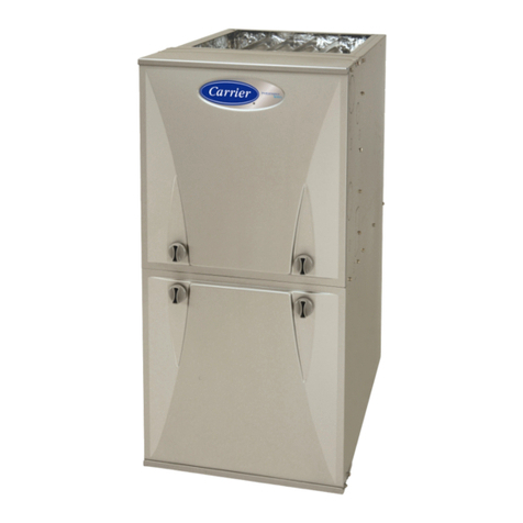
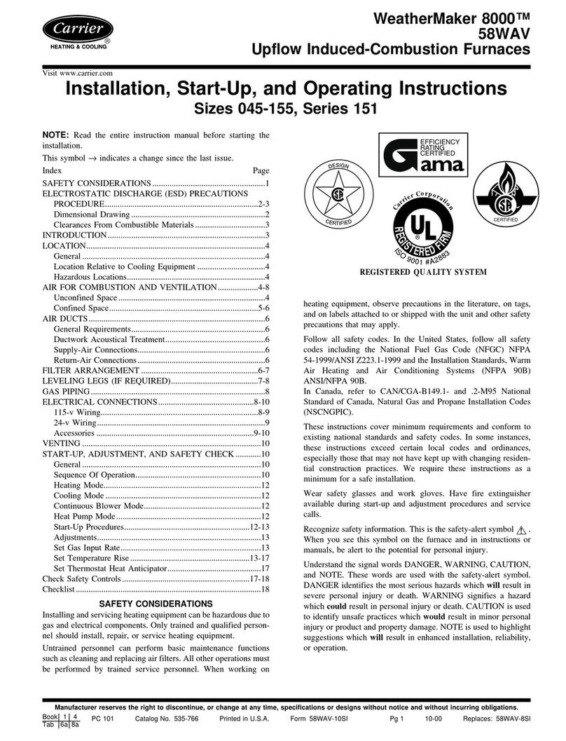
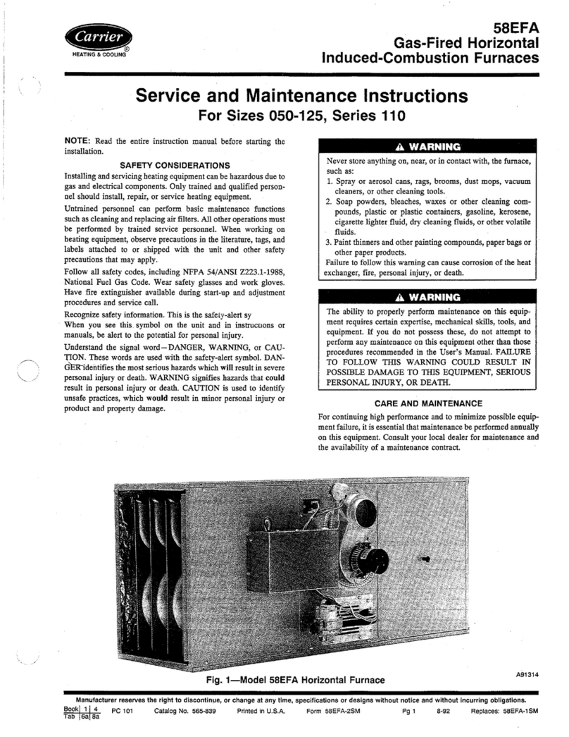
  9. Carrier GAS FURNACE 58MTA Instructions and recipes

Carrier GAS FURNACE 58MTA Instructions and recipes

Other manuals for GAS FURNACE 58MTA

3

Other Carrier Furnace manuals

Carrier 379C/HO User manual

Carrier

Carrier 379C/HO User manual

Carrier R95ESN Guide

Carrier

Carrier R95ESN Guide

Carrier 398A User manual

Carrier

Carrier 398A User manual

Carrier 58MEB Instructions and recipes

Carrier

Carrier 58MEB Instructions and recipes

Carrier 59SE5A Guide

Carrier

Carrier 59SE5A Guide

Carrier GAS FURNACE 58MTA Instructions and recipes

Carrier

Carrier GAS FURNACE 58MTA Instructions and recipes

Carrier 58TUA Instructions and recipes

Carrier

Carrier 58TUA Instructions and recipes

Carrier 58SP0A Guide

Carrier

Carrier 58SP0A Guide

Carrier 58TMA Instructions and recipes

Carrier

Carrier 58TMA Instructions and recipes

Carrier GAS FURNACE 58MVP Instructions and recipes

Carrier

Carrier GAS FURNACE 58MVP Instructions and recipes

Carrier 58DRC User manual

Carrier

Carrier 58DRC User manual

Carrier 58CLA Operation manual

Carrier

Carrier 58CLA Operation manual

Carrier Infinity 59TN6A Operation manual

Carrier

Carrier Infinity 59TN6A Operation manual

Carrier 58MXA 170 Series Instructions and recipes

Carrier

Carrier 58MXA 170 Series Instructions and recipes

Carrier F97CMN Guide

Carrier

Carrier F97CMN Guide

Carrier 58DP Dimensions and installation guide

Carrier

Carrier 58DP Dimensions and installation guide

Carrier 58SX040 User guide

Carrier

Carrier 58SX040 User guide

Carrier 58DP User manual

Carrier

Carrier 58DP User manual

Carrier 58MVB Series Installation and user guide

Carrier

Carrier 58MVB Series Installation and user guide

Carrier 140/E Series Guide

Carrier

Carrier 140/E Series Guide

Carrier A10247 User manual

Carrier

Carrier A10247 User manual

Carrier 58ZAV Series Guide

Carrier

Carrier 58ZAV Series Guide

Carrier KGANP5201VSP User manual

Carrier

Carrier KGANP5201VSP User manual

Carrier 58TUA Instructions and recipes

Carrier

Carrier 58TUA Instructions and recipes

Popular Furnace manuals by other brands

Unitary products group AHV8 UH installation manual

Unitary products group

Unitary products group AHV8 UH installation manual

VERDER CARBOLITE GERO RHF 14/8 Installation, operation and maintenance instructions

VERDER

VERDER CARBOLITE GERO RHF 14/8 Installation, operation and maintenance instructions

Tempstar B Series Service and technical support manual

Tempstar

Tempstar B Series Service and technical support manual

Armstrong EG7H SERIES Installation and maintenance instructions

Armstrong

Armstrong EG7H SERIES Installation and maintenance instructions

Payne PG92ESA Installation, start-up, operating and service and maintenance instructions

Payne

Payne PG92ESA Installation, start-up, operating and service and maintenance instructions

NANOE Zetasinter Operation manual

NANOE

NANOE Zetasinter Operation manual

SUPREME FEM10-M2301CM-A Installation instructions and homeowner's manual

SUPREME

SUPREME FEM10-M2301CM-A Installation instructions and homeowner's manual

Johnson Controls TM9T User's information manual

Johnson Controls

Johnson Controls TM9T User's information manual

Fluke 9118A user manual

Fluke

Fluke 9118A user manual

Lennox EL195UHE Elite Series Unit information

Lennox

Lennox EL195UHE Elite Series Unit information

Intertherm M7RL Series user manual

Intertherm

Intertherm M7RL Series user manual

HDG Pelletmaster 15 Operation manual

HDG

HDG Pelletmaster 15 Operation manual

Nortek MG2S Series installation instructions

Nortek

Nortek MG2S Series installation instructions

VERDER CARBOLITE GERO ABF 8/28 Installation, operation and maintenance instructions

VERDER

VERDER CARBOLITE GERO ABF 8/28 Installation, operation and maintenance instructions

Goodman GMV9 Installation & operating instructions

Goodman

Goodman GMV9 Installation & operating instructions

SUPREME SUP10-M2301C Installation instructions and homeowner's manual

SUPREME

SUPREME SUP10-M2301C Installation instructions and homeowner's manual

Dettson AMT400B34-SM1PMA Installation instructions and homeowner's manual

Dettson

Dettson AMT400B34-SM1PMA Installation instructions and homeowner's manual

Evcon DGD 60 MBH installation instructions

Evcon

Evcon DGD 60 MBH installation instructions

manuals.online logo
manuals.online logoBrands
  • About & Mission
  • Contact us
  • Privacy Policy
  • Terms and Conditions

Copyright 2025 Manuals.Online. All Rights Reserved.

HEATING & COOLING
58MTA
Deluxe 4-Way Multipoise 2-Stage
Direct Vent Condensing Gas Furnace
Visit www.carrier.com
Installation, Start-up, and Operating Instructions
Sizes 060-120
NOTE: Read the entire instruction manual before starting the
installation.
This symbol + indicates a change since the last issue.
A93040
TABLE OF CONTENTS
SAFETY CONSIDERATIONS ..................................................... 2
INTRODUCTION .......................................................................... 2
CODES AND STANDARDS ........................................................ 3
Safety ......................................................................................... 3
General Installation ................................................................... 3
Combustion and Ventilation Air .............................................. 3
Duct Systems ............................................................................ 3
Acoustical Lining and Fibrous Glass Duct .............................. 3
Gas Piping and Gas Pipe Pressure Testing .............................. 3
Electrical Connections .............................................................. 5
ELECTROSTATIC DISCHARGE (ESD) PRECAUTIONS ........ 5
APPLICATIONS ............................................................................ 6
General ...................................................................................... 6
Upflow Applications ................................................................. 6
Condensate Trap Location (Factury-Shipped
Orientation) .......................................................................... 6
Condensate Trap Tubing fEactory-Shipped
Orientation) .......................................................................... 6
Condensate Trap Location tAlternate Upflow
Orientation/ .......................................................................... 7
Condensate Trap Tubing (Alternate Upflow Orientation/.7
Condensate Trap Field Drain Attachment .......................... 8
Pressure Switch Tubing ....................................................... g
Upper. Collector Box and Inducer Housing (Unused)
Drain Connections ............................................................... 8
Condensate Trap Freeze Protection .................................... 8
Downflow Applications ............................................................ 8
Condensate Trap Location .................................................. 8
Condensate Trap Tubing ..................................................... 8
Condensate Trap Field Drain Attachment .......................... 9
Pressure Switch Tubing ....................................................... 9
Condensate Trap Freeze Protection .................................... 9
Horizontal Left (Supply-Air Discharge) Applications ............ 9
Condensate Trap Location .................................................. 9
Condensate Trap Tubing ................................................... 10
Condensate Trap Field Drain Attachments ...................... 10
Pressure Switch Tubing ..................................................... l0
Condensate Trap Freeze Protection .................................. I1
Constrnct a Working Platform .......................................... 11
Horizontal Right (Supply-Air Discharge) Applications ........ 1I
Condensate Trap Location ................................................ I 1
Condensate Trap Tubing ................................................... I 1
Condensate Trap Field Drain Attachment ........................ 12
Pressure Switch Tubing ..................................................... 12
Condensate Trap Freeze Protection .................................. 12
Construct a Working Platform .......................................... 12
LOCATION .................................................................................. 13
General .................................................................................... 13
Furnace Location Relative to Cooling
Equipment ............................................................................... 13
Hazardous Locations ............................................................... 14
INSTALLATION ......................................................................... 14
Leveling Legs (If Desired) ..................................................... 14
Installation in Upflow and Downflow
Applications ............................................................................ 14
Installation in Horizontal Applications .................................. 16
Air Ducts ................................................................................. 16
General Requirements ....................................................... 16
Ductwork Acoustical Treatment ....................................... 16
Supply Air Connections .................................................... 16
Return Air Connections ..................................................... t6
Filter Arrangement .................................................................. 17
Bottom Closure Panel ............................................................. 18
Gas Piping ............................................................................... 18
Electrical Connections ............................................................ 19
115-V Wiring ..................................................................... 19
24-V Wiring ....................................................................... 2l
Accessories ........................................................................ 21
Direct Venting ......................................................................... 23
Remov,'d of Existing Furnaces from Common Vent
Systems .............................................................................. 23
Combustion-Air and Vent Piping ..................................... 24
Concentric Vent and Combustion-Air Ternlination
Kit Installation ................................................................... 28
Multiventing and Vent Terminations ................................ 32
Condensate Drain .................................................................... 32
General ............................................................................... 33
Application ......................................................................... 33
Condensation Drain Protection ......................................... 34
START-UP ADJUSTMENT AND SAFETY CHECK .............. 34
General .................................................................................... 34
Sequence of Operation ............................................................ 35
Two-Stage Heating With Single-Stage Thermostat
(Adaptive Model ................................................................ 35
Manufacturer reserves the right to discontinue, or change at any time, specifications or designs without notice and without incurring obligations.
PC 101 Catalog No. 535-80042 Printed in U.S.A. Form 58MTA-3SI Pg 1 7-02 Replaces: 58MTA-1SI
Two-Stage Heating With Two-Stage Thermostat
(Non-Adaptive Heating Model ......................................... 36
Cooling Mode .................................................................... 36
Thermidistat Mode ............................................................ 39
Continuous Blower Mode ................................................. 39
Heat Pump ......................................................................... 40
Start-Up Procedures ................................................................ 40
Purge G_L_ Lines ................................................................ 40
Component Self-Test ......................................................... 40
Prime Condensate Trap With Water ................................. 40
Operate Furnace ................................................................. 41
Furnace Restart .................................................................. 4 I
Adjustments ............................................................................. 4 I
Set Gas Input Rate ............................................................ 41
Set Temperature Rise ........................................................ 45
Adjust Blower Off Delay (Heat Mode) ............................ 46
Set Thermostat Heat Anticipator ...................................... 46
Check Safety Controls ............................................................ 47
Checklist .................................................................................. 47
RATING
CERTIFIED
REGISTERED QUALITY SYSTEM
SAFETY CONSIDERATIONS
Application of this furnace should be indoors with special
attention given to vent sizing and material, gas input rate, air
temperature rise, unit leveling, and unit sizing. Improper
installation or misapplication of furnace can require excessive
servicing or cause premature component failure.
Improper installation, adjustment, alteration, service, mainte-
nance, or use can cause carbon monoxide poisoning, explo-
sion. fire. electrical shock, or other conditions which may
cause personal injury or property damage. Consult a qualified
installer, service agency, local gas supplier, or your distribu
tot or branch for information or :Lssistance. The qualified
installer or agency must use only factory-authorized and
listed kits or accessories when modifying this product. Failure
to follow this warning could result in electrical shock, fire.
personal injury, or death.
Installing and servicing heating equipment can be hazardous due to
gas and electrical components. Only trained and qualified
personnel should install, repair, or service heating equipment.
Untrained personnel can perform basic maintenance functions
such as cleaning and replacing air filters. All other operations must
be performed by trained service personnel. When working on
2
heating equipment, observe precautions in literature, on tags, and
on labels atlached to or shipped with unit and other safety
precautions that may apply.
These instructions cover the minimum requirements and conform
to existing national standards and safety codes. In some instances,
these instructions exceed certain local codes and ordinances,
especially those that may not have kept up with changing residen
tial constt_ction practices. We require these instructions xs a
minimum for a safe installation.
We,u- safety glasses and work glo_es.
--9
Have a fire extinguisher available during start-up and adjustment
procedures and service calls.
Recognize safety information, This is the safety-alert symbol z_,
When you see this symbol on the unit and in instructions or
manuals, be alert to the potential for personal injury.
Understand these signal words: DANGER, WARNING, CAU-
TION, and NOTE. These words are used with the safety-alert
symbol. DANGER identifies the moat serious hazards which will
result in severe personal injuD" or death. WARNING sigltifies
hazards which could result in personal injury or death. CAUTION
is used to identify unsafe practices which would result in minor
personal injury or product and property" damage. NOTE is used to
highlight suggestions which will result in enhanced installation,
reliability, or operation.
AIRFLOW
-CY
AIRFLOW
AIRFLOW
A93041
Fig. 1--Multipoise Orientations
INTRODUCTION
The model 58MTA, 2-Stage, 4-way multipoise, Gas-Fired, Cat
egory IV, direct vent condensing furnace is available in model
sizes ranging in high-stage gas input rates of 60,000 to 120.000
Btuh. This furnace is C.S.A. design-certified for natural and
propane gases (see furnace rating plate) and for installation in
alcoves, attics, basements, closets, utility rooms, crawlspaces, and
garages. This furnace is factory-shipped for use with natural gas. A
C.S.A. listed gas conversion kit is required to convert furnace for
use with propane gas.
This furnace shall not be installed directly on ca_eting, tile, or
any other combustible material other than wood flooring. FOC
downflowinstallations,afactoryaccessoryfloorbasemustbe
usedwheninstalledoncombustiblematerialsandwoodflooring.
Specialbaseisnotrequiredwhenthisfurnaceisthstalledonthe
mmmthcturer'scoilassemblyorwhenthemanufacturer'scoilbox
isused.Thedesignofthe5gMTAfurnaceisnotC.S.A,(A.G.A.
andC.G.A.)certifiedforinstallationinmobilehomes,recreational
vehicles,oroutdoors.This furnace is suitable for installation in a
structure built on site or a manufactured budding completed at
final site.
1. Combustion products must be discharged outdoors, Connect
this furnace to an approved vent system only, ,'tqspecified in
the "Venting" section of these instructions
2. Never test for gas leaks with an open flame. Use a commer-
cially available soap solution made specifically for the detec-
tion of leaks to check all connections, as specified in the "Gas
Piping" and "Stari-Up, Adjustment, and Safety Cbeck" sec-
tion.
3. Always install furnace to operate within the furnace's intended
temperature-tise range with a duct system which has an
external static pressure within the allowable range, as speci-
fied in the "Adjustments" section. See furnace rating plate.
4. When a furnace is installed so that supply ducts carry air
circulated by the furnace to areas outside the space containing
the furnace, the return air shall also be handled by duct(s)
sealed to the furnace casing and terminating outside the space
containing the furnace.
5. Agas-fired furnace for installation in a residential garage must
be installed as specified in the warning box in the "'Location"
section.
6. The furnace is not to be used for temporary heating of
buildings or structures under construction.
This furnace is designed lk,r continuous return-air minimum
temperature of 60 °F db or intermittent operation down to 55°F db.
Return-air temperature must not exceed 85°F db, See Fig. 4.
This furnace is shipped with the drain and pressure tubes con-
nected for UPFLOW applications. Minor modifications are re-
quired when used in DOWNFLOW, HORIZONTAL RIGHT,
or HORIZONTAL LEFT Isupply-air discharge direction) appli-
cations as shown in Fig. 1. See details in Applications section.
This furnace must be installed with a direct-vent (combustion air
and flue) system and a factory accessory termination kit. In a
direct-vent system, all air for combustion is taken directly from the
outdoor atmosphere and all flue gases are discharged to the
outdoor atmosphere. See furnace and factor,,' accessory vent-air
intake termination kit instructions for proper installation.
This furnace is shipped with the following materials to a,_sist in
proper furnace installation. These materials are shipped in the main
blower compartment.
Installer Packet includes:
Installation, Startup, and Operating Instructions
Service and Maintenance Instructions
User's Information Manual
Warranty Certificate
Loose Parts Bag includes: Quantit
Pressure tube extension 1
Collector Box or condensate trap extension tube t
Inducer housing drain tube 1
l/2qn CPVC street elbow 2
Drain tube coupling 1
Drain tube coupling grommet 1
Vent and combustion-air intake pipe support 2
Condensate trap hole filler plug 3
Vent and combustion-air intake hole filler plug 2
Cornbustioo-air intake pipe podorated disk assembly 1
Vent Pipe Extension 1"
• ONLY supplied with some furnaces.
For accesso_, installation detail, refer to the accessory, installation
instruction.
NOT[:: Remove all shipping materials before operating furnace.
CODES AND STANDARDS
Follow all national and local codes and standards in addition to
these instructions. The installation must comply with regulations
of the serving g_s supplier, local building, heating, plumbing, and
other codes. In absence of local codes, the installation must
comply with the national codes listed below and ,all authorities
having jurisdiction,
In the United States and Canada, follow all codes and standards for
the following:
Step 1--Safety
US: National Fuel Gas Code (NFGC) NFPA 54-1999/ANSI
Z223.1-1999 and the Installation Standards, Warm Air Heating
and Air Conditioning Systems ANSI/NFPA 90B
• CANADA: CSA B149.1-00 National Standard of Canada,
Natural Gas and Propane Installation Code (NSCNGP1C)
Step 2--General Installation
US: current edition of the NFGC and the NFPA 90B. For
copies, contact the National Fire Protection Association Inc.,
Battery, march Park, Quincy, MA 02269: or for only the NFGC
contact the American Gag Association, 400 N. Capitol., N.W.,
Washington DC 20001
• CANADA: NSCNGPIC. For a copy. contact Standard Sales,
CSA International, 178 Rexdale Boulevard. Etobicoke (Tor-
ontoh Ontario, M9W IR3, Canada.
Step 3---Combustion and Ventilation Air
•US: Section 5.3 of the NFGC. Air for Combustion and
Ventilation
• CANADA: part 7 of the NSCNGPIC. Venting Systems and Air
Supply for Appliances
Step 4--Duct Systems
US and CANADA: Air Conditioning Contractors Association
IACCA! Manual D, Sheet Metal and Air Conditioning Con-
tractors National Association (SMACNA), or American Soci
ety of Heating, Refrigeration, and Air Conditioning Engineers
(ASHRAEI 2001 Fundamentals Handbook Chapter 34.
Step 5---Acoustical Lining and Fibrous Glass Duct
US and CANADA: current edition of SMACNA, NFPA 90B as
tested by UL Standard 181 for Class 1 Rigid Air Ducts
Step 6--Gas Piping and Gas Pipe Pressure Testing
• US: NFGC; chapters 2, 3.4, and 9 and national plumbing codes
• CANADA: NSCNGPIC Parts 3.4, 5, A. B, E, G, and H.
2-IN. COMBUSTION-
2-IN. VENT SONN
_-IN. DIA THERMOSTAT
ENTRY
!7 ............. *q_
T
14 _ SIDE INLET
TYP
T
I"-D- 23 'a'TYP
SIDE INLET
_'_ 26 _,w TYP
f ONDENSATE DRAIN
TRAP LOCATION
(DOWNFLOW &
HORIZONTAL LEFT)
F hqN DIA
POWER CONN
ACCESSORY
POWER ENTRY
i"-_'-'- CO ND EN SAT E l
DRAIN TRAP
LOCATION
(ALTERNATE 4
UPFLOW)
TYP
CONDENSATE
DRAIN LOCATION
(UPFLOW)
AIRFLOW
TYR
_NLET
tI,i_, 41= _ E ...._.._p
TYP
L
CONDENSATE DRAIN
TRAP LOCATION _
(DOWNFLOW &
Hon{ZONTAL RIGHT) _
OR ALTERNATE
!_-IN, DIA GAS CONN
1
_28_ _1
_26 t_t_ "r--
26 _/_r
22 S'I_¸¸ I_
19_ "_-- I_ ¸
--+ _2-1N CONMNBUSTION- -_-
AIR CO s_la,,
_'-"_ _"zIN DIA
THERMOSTAT ENTRY
,f2-1N VENT CONN
I S_DE INLET
i
397_
_E**+_............ A+
J_I 24 '1' _ _ '1' rr
DIMPLE LOCATORS BOTTOM INLET
FOR HORIZONTAL
HANGING
NOTES: 1. Minimum return-air openings at furnace, based on metal duct. If flex duct is used,
see flex duct manufacturer's recommendations for equivalent diameters.
2. Minimum return-air opening at furnace:
a. For 800 CFM-16-in. round or 14'/_x 12-in. rectangle.
b. For 1200 CFM-20-in, round or 14'/= x 19'/_-in. rectangle.
c. For 1600 CFM-22-in, round or 14% x 23%-in. rectangle,
d. For airflow requirements above 1800 CFM, see Air Delivery table in Product Data
literature for specific use of single side inlets. The use of both side inlets, a
combination of 1 side and the botlom, or the bottom only will ensure adequate
return air openings for airflow requirements above 1800 CFM at 0.5" W.C. ESP.
UNIT SIZE D E
060-12 15-7/8 16
080-12 15-7/8 16
080-16 15-7/0 16
100-16 19-3/8 19-1/2
100-20 19-3/8 19-1/2
120-20 22-7/8 23
DIMENSIONS (IN,)
A
17-1/2
17-1/2
17-1/2
21
21
24-1/2
Fig. 2--Dimensional Drawing
A02149
INSTALLATION
_sforcedalrfum_c_iseqlJippedfor_w_lna_at;_ltltudes0-10,030ff(0 3,(T_Ont,ex_140sizeFumaces_eo_app_edforaYdbJdeS0 7,000_t(0-2.135m)
_accesso__suppled_ _emz_acturef,sh_beusedtoo0_ to0nX_aneg_ useormay_ _ _ _ _ _ _ .
*i_,sfurnace is forindo_ inst_la_Xl m a I_ildng cons_uctedon site. 1_=s_mac_ rn_y_ _ _ a_(_l_) _ _ _ _ r_ _e _ _ _
au61cr_edk&
_lLsfunitemaybeinsl_le3oncorrl>Jsa_efloodngin_o3_eorct_setalrd_mum_rance fromc_ _
3_isap_iancerequ_esaspeoalv_r_ systemRefertotheinsta_at_ninstnJc_3nsloq_ls listandrrelt_dofinst_ _ _ __ _ _ _ _, _
CP_, or A_pipe._mdst n0(13e,_nledincomrno_wil_o_e_as-flred_oplia_x_5. C_oughwttchv_r __ _24i_
(_O0r//n), nirirnum 3/4 i_c_ (19 ram)It,_ (inditing roo_g _).
Cette foun_se _ _r Dul_ e_t _F_oee pour_l_a_ avec _az nab_el elalludes _ _e 0 3,050m
((3-10,000p_).exc_pt_ c_ f_ d_ 140t_Jle so_tp_J" a_ oomp_ _02.13r_n(0 -7.000 p)
U_liSe:_ne tn_Jssede cor_er_on _un_e pa_le P_, 9our pa_:_r au g_z 10ropal_OUpourcertal_ _ _ _ _d.
Cede fourna_ea a_ p_s$ e_tpou_ins_la_ &I_nt_neu_d,3nsunt_rnent cor_ _Zl_. _ _ _ _ _ _ _ i_ _ _ n_ _
(m_son m0t_le)_i_e_cnt p_"la 13_ 9gnal_t_ et s_I_utd_ une trousses_c_ _ _ _
Cette _n_,se peut Otre _lee surunplan:t_ _e d_s uqer_ =._ ou unI_ac_d en obsen'ant les d_ga_ _p_ _ _ _.
Cotapp_e_l rV_c_e un s'yst_ d _wacu_on speo_. La _d_st_la_on etI_ li_e OesI_CeS _ _ _ _ _ d_e _ _
sd_liseravecbvJvaute_e_snon_mc_tures4OPVC, PVC-Dv_CPVC, ou _et _enepeut pas_e'even_l_econj_r_nent a_ecd'au0_esappa_etsb_z. Em_=_=urdela
O0_ au b-aveesde laque_e il est 13ec=_oleda _re passer los luyal_ d a_ra_on (adrrissloW_): 24 _ (_ _) _ _4 _ (19_) _ (y _ _ t_e).
FO_up_oN and do_ applications, fu_ must be instaJ_=dleve_ or i_ched ',_thn 1_
of level FOr a hor_ 8Dplica_on, the flJ_ nlu_ be pltch_ rclr_rnum 1/4"to
ma_mum of 112"forv_ for 17:operdrainage. See Ir_lafa_n Manual for IMI_RTANT urlt
suppo:tdstals_n_al ap_on_
Pour des ;_oplic_honsde flL_ ascendant _ d_ce_a_t, la f_um_se d_t _tre ir_tall_ _
nive_u o_ in:tir_e a I_ plus de 1/2" du nlv_ Pour une _of_iG_tJ(_ honz(_ltate, ta
fcorna_ dot_treinc_r'eeervrer_ran_m1/4"etrn_ornum1/'Z'cIJrw_aJ0_r teciranage
&Encasdin_tall_nen "on_onzo_de,oo_ulterlesnE_rr_nts
la_3_ANTS surle _cons e_rna_ dinst_la_on.
MINIMUM INCHES CLEARANCE TO COMBUSTIBLE CONSTRUCTION
ALL pO_I'I1ONS:
_t _,lnimumflontclearancef_-serv,,ce30inches(762mm).
1_)Nzefurnacesrequre1inchbackdeetancetocontJustiUerr_e_ais
As_t:_y,Part NO.CD5c_CKS,_ C_ICasing,PadNo,KCAKC.
Linecc_tact _pen'tis_iNe onty I_ lines fc_n'_d by intefs_<;ns of top and t_.o s_:_esof furnac_
§ _earancesho_nisf_r_ir_et and_r o_e_end_
DEGAGEMENTMINIMUMENPOUCESAVECELEMENTSDECONSTRUCTIONCOMBUSTIBLES
POUR TOIJS LES POSITIONS:
_t [_g_m'_ a'_"tmr"raur_de7mmmI_0P°)linerre_r_Jm"
Fr_H_s fo_ de t40 taille. I po (25ram) de_age_T_nt des rmd_ _e6t requ_
LA9o_moNCQURA_TDE_CENOANT:
F_rli_taflatio_s_le combu_il_es4_ulementonutiliselabase "1 e,l:_ce
noK_L_OIALL _eserpefllir_ pie_en °_CKS,_ulecarter_n, piece
noKCAKC
POURLAPOSfllONHORIZONTALE:
Le cc_tact n'e_t _ent re les lignesfomt_ par les intemec1_onsdu desks et des d_es de la
<3_s_ _ I__i_e, _ d_ _iw_, desrnor_ <_delaCf_te duI_ment.
La _stance indquee co_ceme I'ext_wt e du d'ardvee d'air etr e_h_Tite du tuyau de sodie d'_r.
Pourlosfc_na_s de120el140lalle,1po(l_) degagerne_desmatena_o0rd0us_t_estrec@s
_, 324999-201 REV.D {LITTOP)
L_VEL (0") ,, MIN 114"
TO TO
1/2" MA _ ! i ,q
_RONT I r --
UPFLOWOR _"_ FFRONT _[
11 _ HORIZONTAL
DOWNFLOW L_
_lls lumace is aporoved for UPR_OW, DOVe, FLOWaed
C_te foun_se e_ al_oev_e pc_ 1ins_la_n HOFI;_ONTALE
ena circui_f!_ d air V_ LE HAUT etVERS LEBAS.
JA02148
--) Fig. 3_Clearances to Combustibles
ELECTROSTATIC DISCHARGE (ESD) PRECAUTIONS
PROCEDURE
"_ _ MAX 851=
>_
FRONT
RETURN
AIR MIN 55°F
A93042
Fig. 4_Return-Air Temperature
Step 7--Electrical Connections
•US: National Electrical Code (NEC) ANSI/NFPA 70-2002
•CANADA: Canadian Electrical Code CSA C22.1
Use this procedure for ,all installed ,and aninstalled furnaces. An
ESD service kit _available from commercial sources) may be used
to prevent ESD damage.
Electrostatic discharge can affect electronic components.
Follow the Electronic Discharge Precautions Procedure listed
below during furnace inLstallation and servicing to protect the
furnace electronic control. Precautions will prevent electro-
static discharges from personnel and hand tools which are
held during the procedure. These precautions will help to
avoid exposing the control to electrostatic discharge by
putting the furnace, the control and the person at the same
electrostatic potential.
I. Disconnect all power to the furnace. Multiple disconnects may
be required, DO NOT TOUCH THE CONTROL OR ANY
WIRE CONNECTED TO THE CONTROL PRIOR TO DIS-
CHARGING YOUR BODY'S ELECTROSTATIC CHARGE
TO GROUND.
2. Firmly touch the clean, unpainted, metal surface of the furnace
chassis which is close to the control. Tools held in hand during
grounding will be discharged.
FBLOWERSHELF FURNACE
_[_ _)R FCONDENSATE
CONDENSATE TRAP
f--TRAP (INSIDE FURNACE
SIDE
FIELD 26¼ t'/2
DRAIN
LALTERNATEDRAIN CONN
TUBE LOCATION
CONDENSATETRAP _ SIDE VIEW FRONT VIEW
DRAINTUBE LOCATION DOWNFLOW AND ALTERNATE
UPFLOW APPLICATIONS EXTERNAL UPFLOW APPLICATIONS
FURNACE
OOO_ _ FURNACE
SIDE
4
_../ 26 ¼ ¾
FIELD
DRAIN
CONN
END VIEW FRONT VIEW
HORIZONTAL
APPLICATIONS
SLOT O 2gN%7
APPLICATION
(OPTIONAL)
(WHEN USED)
FRONT VIEW
1/40D
COLLECTOR BOX TO
TRAP RELIEF PORT
I_OD
INDUCER HOUSING
"'L_.- DRAIN CONNECTION
s/aO D
iCOLLECTOR BOX
' DRAIN CONNECTION
SCREW HOLE FOR
_ UPFLOW OR DOWN-
'FLOW APPLICATIONS
(OPTIONAL)
21/4 _ _ _/_IN. PVC OR CPVC
SIDE VIEW
Fig. 5_Condensate Trap
A93026
3. You may proceed to service the control or connecting wires as
long as you do nothing to recharge your body (moving or
shuffling feet, touching ungrounded objects, etc./.
4. If you touch ungrounded objects, firmly touch a clean,
unpainted metal surface again before touching control or
wires.
5. Before removing a new control I?om its container, discharge
your body's charge to ground. If the control is to be installed
in a furnace, follow items 1 through 4 before bringing the
control or yourself in contact with the furnace. Put all used and
new controls into containers before touching ungrounded
objects.
APPLICATIONS
Step l_General
Some assembly and modifications are required for furnaces
installed in any of the 4 applications shown in Fig. 1. All drain and
pressure rubes are connected as shown in Fig. 6. See appropriate
application instructions for these procedures.
Step 2--Upflow Applications
In an upflow application, the blower is located below the burner
section, and conditioned air is discharged upwards.
CONDENSATE TRAP LOCATION (FACTORY-SHIPPED
ORIENTATION)
The condensate trap is factory installed in the blower shelf and
factory connected for UPFLOW applications. A factory-supplied
tube is used to extend the condensate trap drain connection to the
desired furnace side for field drain attachment. See Condensate
Trap Tubing (Factory-Shipped Orientation) section for drain tube
extension details. (See Fig. 5.)
CONDENSATE TRAP TUBING (FACTORY-SHIPPED
ORIENTATION)
NOTE: See Fig. 6 or tube routing label on main furnace door to
confirm location of these tubes.
1. Collector Box Drain, Inducer Housing Drain, Relief Port, and
Pressure Switch Tubes
These tubes should be factory attached to condensate trap and
pressure switch ready for use in upflow applications. These
tubes can be identified by their connection location and ,also
by a color label on each tube. These tubes _e identified as
follows: collector box drain tube (blue label Linducer housing
drain tube (violet label or moldedL relief port robe (green
label), and pressure switch tube (pink label).
2. Condensate Trap Drain Tube
The condensate trap drain connection must be extended for
field attachment by doing the following:
a. Determine location of field drain connection. (See Fig. 2 or
6.)
NOTE: If iaternal filter or side Filter/Media Cabinet is used, drain
tube should be located to opposite side of casing of return duct
attachment to assist in filter removal.
6
O /
DRAIN TUBE (BLUE
& WHITE STRIPED)
COLLECTOR BOX --'_
TUBE (PINK)
TUBE (GREEN)
(MOLDED) DRAIN
TUBE (BEHIND
COLLECTOR BOX
DRAIN TUBE)
DRAIN TUBE (BLUE)
DRAIN TUBE (BLUE
& WHITE STRIPED)
TUBE (PINK)
COLLECTOR BOX
TUBE (GREEN)
DRAIN TUBE (BLUE)
TRAP
FACTORY-SUPPLIED
DRAIN TUBE
COUPLING (LEFT
DRAIN OPTION)
FIELD-INSTALLED
FACTORY-SUPPLIED
DRAIN TUBE
FIELD-INSTALLED
FACTORY-SUPPLIED
lf2qN. CPVC STREET
ELBOWS (2) FOR
LEFT DRAIN OPTION
FIELD-INSTALLE[
FACTORY-SUPPLIED
DRAIN TUBE
COUPLING (RIGHT
BRAIN OPTION) A01030
Fig. 6--Factory-Shipped Upflow Tube
Configuration
(Shown with Blower Access Panel Removed)
b. Remove and discard casing drain hole plug button from
desired side.
c. Install drain tube coupling grommet (factory-supplied in
loose parts bag) in selected casing hole.
d. Slide drain tube coupling (factory-supplied in loose parts
bag) through _ommet ensuring long end of coupling faces
blower.
e. Cement 2 factory-supplied l/2-in, street CPVC elbows to
the rigid drain tube connection on the condensate trap. (See
Fig. 6.) These elbows must be cemented together and
cemented to condensate trap drain connection.
NOTE: Failure to use CPVC elbows may allow drain to kink and
prevent draining.
f. Connect larger diameter drain tube and clamp (factory-
supplied in loose parts bag) to condensate trap and clamp
securely.
g. Route tube to coupling and cut to appropriate length.
h. Attach tube to coupling and clamp securely.
CONDENSATE TRAP LOCATION (ALTERNATE UPFLOW
ORIENTATION)
An alternate location for the condensate trap is the left-hand side
of casing. (See Fig, 2 and 7.)
HOUSING
DRAIN TUBE
(VIOLET)
7
Fig. 7--Alternate Upflow Configuration and Trap
Location
NOTE: If the alternate left-hand side of casing location is used,
the factory-connected drain and relief port tubes must be discon-
nected and modified for attachment. See Condensate Trap Tubing
/Ahernate Upflow Orientation) section for tubing attachment. To
relocate condensate trap to the left-hand side. perform the follow-
ing:
1. Remove 3 tubes connected to condensate trap.
2. Remove trap from blower shelf by gently pushing tabs inward
and rotating trap.
3, Install casing hole filler cap (factory-supplied in loose parts
bag) into blower shelf hole where trap was removed.
4, Install condensate trap into left-hand side casing hole by
inserting tube connection stubs through casing hole and
rotating undl tabs snap into locking position.
5, Fill unused condensate trap casing holes with plastic filler
caps (factory-supplied in loose parts bag).
CONDENSATE TRAP TUBING (ALTERNATE UPFLOW ORI
ENTATION)
NOTE: See Fig. 7 or tube routing label on main furnace door to
confirm location of these tubes.
I, Collector Box Drain Tube
Connect collector box drain tube (blue label) to condensate
trap.
NOTE: On 17-1/2 in. wide furnaces ONLY. cut tube between
corrugated sections to prevent kinks from occmring.
2. Inducer Housing Drain Tube
a. Remove and discard LOWER (molded) inducer housing
drain tube which wa._ previously connected to condensate
trap.
b.Useinducerhousingdrainextensiontube (violet label and
factory'-supplied in loose parts bagl to connect LOWER
inducer housing drain connection to the condensate trap.
c. Determine appropriate length, cut, and connect tube.
d. Clamp tube to prevent any condensate leakage.
3. Relief Port Tube
a. Connect relief port tube (_een label) to condensate trap.
b. Extend this tube (if required) by splicing to small diameter
tube (factory-supplied in loose parts bag).
c. Determine appropriate length, cut, and connect tube.
CONDENSATE TRAP FIELD DRAIN ATTACHMENT
Refer to Condensate Drain section for recommendations and
procedures.
PRESSURE SWITCH TUBING
The LOWER collector box pressure tube /piak label) is factory,
connected to the High Pressure Switch and should not require any
modification.
NOTE: See Fig. 6 or 7 or tube routing label on main furnace door
to check for proper connections.
UPPER COLLECTOR BOX AND INDUCER HOUSING (UN
USED) DRAIN CONNECTIONS
1. Upper collector box drain connection
Attached to the UPPER collector box drain connection is a
factory-installed corrugated, plugged tube (blue and white
striped label). This tube is plugged to prevent condensate
leakage in this application. Ensure this tube is plugged.
NOTE: See Fig. 6 or 7 or tube routing label on main furnace door
to check for proper connections.
2. Upper inducer housing drain connection
Attached to the UPPER (unused) inducer housing drain
connection is a cap and clamp. This cap is used to prevent
condensate leakage in this application. Ensure this connection
is capped.
NOTE:: See Fig. 6 or 7or tube routing label on main furnace door
to check for proper connections.
CONDENSATE TRAP FREEZE PROTECTION
Refer to Condensate Drain Protection section for recommenda-
tions and procedures.
Step 3_Downflow Applications
In a downflow furnace application, the blower is located above the
burner section, and conditioned air is discharged downwards.
CONDENSATE TRAP LOCATION
The condensate trap must be removed from the factory-installed
blower shelf location and relocated in selected application location
as shown in Fig. 2, 8, or 9.
To relocate condensate trap from the blower shelf to desil_d
location, perform the following:
l. Remove 3 tubes connected to condensate trap.
2. Remove trap from blower shelf by gently pushing tabs inw,'u-d
and rotating trap.
3. Remove casing hole filler cap from casing hole./See Fig. 2, 8,
or 9.)
4. Install casing hole filler cap into blower shelf hole where trap
was removed.
5. Install condensate trap into desired casing hole by inserting
tube connection stubs through casing hole and rotating until
tabs snap into locking position.
DRAIN TUBE (BLUE)
TUBE (GREEN)
COLLECTOR BOX -_.
EXTENSION TUBE
COLLECTOR BOX
TUBE (PINK)
COLLECTOR BOX
DRAIN TUBE (BLUE
& WHITE STRIPED)
COLLECTOR BOX-_,
EXTENSION TUBE
TRAP ©
INDUCER HOUSING-
DRAIN TUBE (VIOLET)
Fig. 8---Downflow Tube Configuration
(Left-Hand Trap Installation)
©©
©
A01023
_" PLUG
F CAP
COLLECTOR BOX
F DRAIN TUBE (BLUE)
COLLECTORBOX
f TUBE(PINK)
COLLECTORBOX
TUBE(GREEN)
COLLECTORBOX
EXTENSIONTUBE
-- COLLECTORBOX
DRAINTUBE (BLUE
&WHITESTRIPED)
"_ COLLECTORBOX
EXTENSIONTUBE
INDUCERHOUSING
DRAINTUBE
_ _VIR(_LET)
.F O ENSATE
_'_"-- COLLECTOR BOX
EXTENSION
DRAINTUBE
A01024
Fig. 9_Downflow Tube Configuration
(Right-Hand Trap Installation)
CONDENSATE TRAP TUBING
NOTE: See Fig. 8 or 9 or tube routing label on main furnace door
to check tbr proper connections.
Relocaterobesasdescribedbelow.
1.CollectorBoxDrainTube
a.Removefactory-installedplugfromLOWER collector box
drain tube tblue and white striped label).
b. Install rentoved cl,-mlp and plug into UPPER collector box
drain tube (blue labell which wa_ connected 1o condensate
trap.
c. Connect LOWER collector box drain connection to con-
densate trap.
(I.) Condensate Trap Located on Left Side of Casing
(a3 Connect LOWER collector box drain tube !blue
and white striped label! to condensate trap. Tube
does not need to be cut.
(b.) Clamp tube to prevent any condensate leakage.
(2.) Condensate Trap Located on Right Side of Casing
(a.! Install drain robe coupling (factory-supplied in
loose parts bag) into collector box drain tube
Iblue and white striped label) which was previ-
ously plugged.
(b.) Connect larger diameter drain tube Ifactory-
supplied in loose parts bag! to drain tube cou-
pling, extending collector box drain tube tbr
connection to condensate trap.
(c.) Route extended collector box drain tube directly
from collector box drain to condensate trap as
shown in Fig. 9.
(d.) Determine appropriate length and cut.
(e.) Connect to condensate trap.
(f.) Clamp tube to prevent any condensate leakage.
2. Inducer Housing Drain Tube
a. Remove factory-installed cap ,and champ from LOWER
inducer housing drain connection.
b. Remove and discard UPPER (molded) inducer housing
drain tube which was previously connected to condensate
trap.
c. Install cap and clamp on UPPER inducer housing drain
connection where molded drain tube was removed.
d. Use inducer housing drain tube (violet label and factory.-
supplied in loose parts bag) to connect LOWER inducer
housing drain connection to the condensate trap.
e. Connect inducer housing drain connection to condensate
trap.
(13 Condensate Trap Located on Left Side of Casing
(a.) Determine appropriate length and cut.
lb.) Connect tube to condensate trap.
(c.I Clan_p tube to prevent any condensate leakage.
(2.) Condensate Trap Located on Right Side of Casing
{a.I Route inducer housing drain tube (violet label)
directly from inducer housing to condensate trap
as shown in Fig. 9.
lb.) Determine appropriate length and cut.
(c.) Connect tube to condensate trap.
(d./ Clamp tube to prevent any condensate leakage.
3. Relief Port Tube
Refer to Pressure Switch Tubing section for connection
procedure.
CONDENSATE TRAP FIELD DRAIN ATTACHMENT
Refer to Condensate Drain section for recommendations and
procedures.
PRESSURE SWITCH TUBING
One collector box pressure tube {pink label) is factory connected to
the High Pressure Switch for use when furnace is installed in
upflow applications. This tube MUST be disconnected and used
for the condensate trap relief port tube. The other collector box
pressure tube (green labell which was factory connected to the
condensate trap relief port connection MUST be connected to the
High Pressure Switch in DOWNFLOW or HORIZONTAL
RIGHT applications
NOTE: See Fig. 8 or qor tube routing label on main furnace door
to check for proper connections.
I. Disconnect collector box pressure tube (pink label) attached to
High Pressure Switch.
2. Extend collector box pressure tube (_m'een label) which was
previously connected to condensate trap relief port connection
by splicing to small diameter tube (factory-supplied in loose
paa_s bag).
3. Connect collector box pressure tube (green label) to High
Pressure Switch connection labeled COLLECTOR BOX.
4. Extend collector box pressure tube (pink label) which was
previously connected to High Pressure Switch by splicing to
remaining small diameter tube (factory-supplied in loose parts
bag).
5. Route this extended tube (pink label) to condensate trap relief
port connection.
6. Determine appropriate length, cut, and connect tube.
7. Clamp tube to relief port connection.
CONDENSATE TRAP FREEZE PROTECTION
Refer to Condensatu Drain Protection section for recommenda-
tions and procedures.
Step 4_Horizontal Left (Supply-Air Discharge)
Applications
In a horizontal left furnace application, the blower is located to the
right of the burner section, and conditioned air is discharged to the
left.
NOTE: In Canada, installations shall be in accordance with
current NSCNGPIC and/or local codes.
CONDENSATE TRAP LOCATION
The condensate trap must be removed from the factory-installed
blower shelf location and relocated in selected application location
as shown in Fig. 2 or 10.
To relocate condensate trap from the blower shelf to desired
location, perform the following:
I. Remove 3 tubes connected to condensate trap.
2. Remove trap from blower shelf by gently pushing tabs inward
and rotating trap.
3. Install casing hole filler cap (factory-supplied in loose parts
bag) into blower shelf hole where trap wos removed.
4. Install condensate trap into left-hand side ca.sing hole by
inserting tube connection stubs through casing hole and
rotating until tabs snap into locking position.
PLUG
AUXILIARY "J" BOX "__
BOX
DRAIN TUBE
(BLUE AND WHITE STRIPED)
CONDENSATE
TRAP COLLECTOR BOX
TUBE(GREEN)
BOX EXTENSION
DRAIN TUBE
COLLECTOR BOX
EXTENStON TUBE
;ERHOUSING
DRAINTUBE(VIOLET)
DRAIN TUBE (BLUE)
DRAIN TUBE COUPLING \
\
COLLECTOR BOX TUBE (PINK) "_"
RELOCATE TUBE BETWEEN BLOWER SHELF AND INDUCER HOUSING FOR
040, 060, AND 080 HEATING INPUT FURNACES A01029
Fig. 10--Horizontal Left Tube Configuration
5. Fill unused condensate trap casing holes with plastic filler
caps (factory-supplied in loose parts bag).
CONDENSATE TRAP TUBING
NOTE: See Fig. 10 or tube routing label on main furnace door to
check for proper connections.
1. Collector Box Drain Tube
a. Install drain tube coupling (factory-supplied in loose parts
bag) into collector box drain tube tblue label) which was
previously connected to condensate trap.
b. Connect large diatueter drain tube and clamp (factory-
supplied in loose parts bag) to drain tube coupling, extend-
ing collector box drain tube.
c. Route extended tube (blue label) to condensate trap and cut
to appropriate length.
d. Clamp tube to prevent any condensate leakage.
2. Inducer Housing Drain Tube
a. Remove and disc,'u-d LOWER (molded) inducer housing
drain tube which was previously connected to condensate
trap.
b. Use inducer housing drain extension tube (violet label and
factory-supplied in loose parts bag) to connect LOWER
inducer housing drain connection to the condensate trap,
c. Determine appropriate length, cut. and connect tube.
d. Clamp tube to prevent any condensate leakage.
3. Relief Port Tube
a. Extend collector box tube (green label) which was previ-
ously connected to the condensate trap by splicing to small
diameter tube (factory-supplied in loose parts bag).
b. Route extended collector box pressure tube to relief port
connection on the condensate trap.
c. Determine appropriate length, cut, and connect tube.
d. Clanlp tube to prevent any condensate leakage.
CONDENSATE TRAP FIELD DRAIN ATTACHMENTS
Refer to Condensate Drain section for recommendations and
procedures.
PRESSURE SWITCH TUBING
The LOWER collector box pressure tube (pink label) is factory
connected to the High Pressure Switch for use when furnace is
installed in UPFLOW applications. This tube MUST be discon-
nected, extended, rerouted, and then reconnected to the pressure
switch in HORIZONTAL LEFT applications for 060 and 080
heating input furnaces.
NOTE: See Fig. 10 or tube routing label on main furnace door to
check for proper connections.
Modify tube as described below:
1. Disconnect collector box pressure tube (pink label) attached to
High Pressure Switch.
2. Use smaller diameter tube I,factory-supplied in loose parts
bag) to extend tube disconnected in item i.
3. Route extended tube:
4.
a. Behind inducer housing.
b. Between blower shelf and inducer housing.
Determine appropriate length, cut. and reconnect tube to High
Pressure Switch connection labeled COLLECTOR BOX.
10