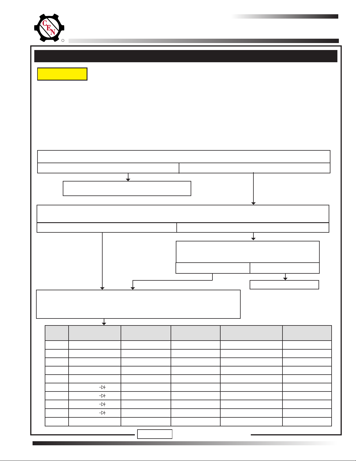
Cen C850 User manual

R
Page 1
TG97A
Hazard Denitions
CAUTION
Indicates presence of hazards that will
or can cause minor personal injury or
damage to equipment.
NOTICE Indicates special instructions on installa-
tion, operation or maintenance that are
important but not related to personal injury hazards.
C850 Alternator
Troubleshooting Guide
C.E. Niehoff & Co.
Battery Conditions
NOTICE Battery conditions may be observed during
cold-start voltage tests until temperatures
of electrical system components stabilize.
Maintenance/Low Maintenance Battery
• Immediately after engine starts, system volts are lower
than regulator setpoint and amp output is medium.
• 3–5 minutes into charge cycle, system voltage increase
and amps decrease.
• 5–10 minutes into charge cycle, system volts increase
to or near regulator setpoint and amps decrease to a
minimum.
• Low maintenance battery has same characteristics as
maintenance battery but slightly longer recharge time.
Maintenance-free Battery
• Immediately after engine starts, system volts are lower
than regulator setpoint and charging amps are low.
• Volts and amps remain low when charge cycle begins.
• After alternator energizes, voltage increases by several
tenths. Amps increase to medium-to-high levels.
• Volts will increase to setpoint and amps will decrease.
Time required to reach optimum voltage and amps will
vary with engine speed, load, and ambient temperature.
High-cycle Maintenance-free Battery. These batter-
ies respond better than standard maintenance-free.
Charge acceptance of these batteries may display char-
acteristics similar to maintenance batteries.
AGM (Absorbed Glass Mat) Maintenance-free
Battery. These dry-cell batteries respond better than
standard maintenance-free batteries. If battery state of
charge drops to 75% or less, recharge batteries to 95%
or higher separately from engine charging system to
avoid damaging charging system components and pro-
vide best overall performance. Charge acceptance may
display
characteristics similar to maintenance batteries.
Contents
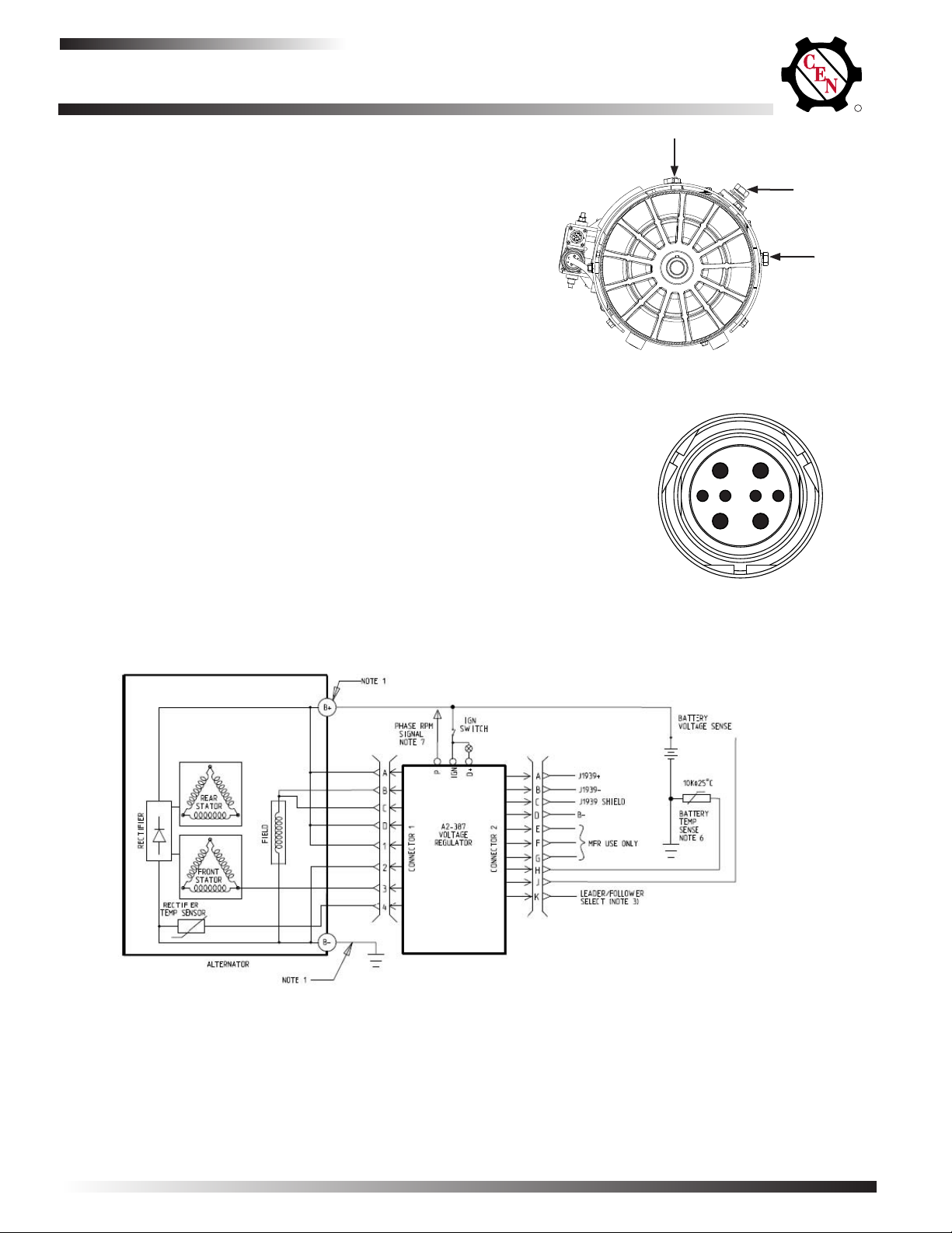
Section A: Wiring Diagram ...........................................2
Section B: Basic Troubleshooting ...............................4
Section C: Advanced Troubleshooting .......................5
Required Tools and Equipment
• Digital Multimeter (DMM)
• Ammeter (digital, inductive)
• Jumper wires
Testing Guidelines
Professional service technicians rely on the following
guidelines when testing electrical components.
Voltage testing:
• Set meter to proper scale and type (AC or DC).
• Zero meter scale or identify meter burden by touching
meter leads together. Meter burden must be subtract-
edfromnalreadingobtained.
• Be sure meter leads touch power source area only.
Prevent short circuit damage to test leads or source
by not allowing meter leads to touch other pins or ex-
posed wires in test area.
• Use CEN tools designed especially for troubleshoot-
ing CEN alternators when available.
Resistance (ohms) testing:
• Set meter to proper scale.
• Zero the meter scale or identify meter burden by
touching meter leads together. Meter burden must be
subtractedfromnalreadingobtained.
• Be sure meter leads touch power source area only.
Donotallowngersorbodypartstotouchmeter
leads or power source during reading.
• Take reading when power source is at 70º F/21º C.
Readings taken at higher temperatures will increase
reading. Conversely, readings taken at lower temper-
atures will decrease reading.
• Test directly at power source. Testing through extend-
ed harnesses or cable extensions may increase read-
ing.
Voltage drop testing:
• Measure voltage between B+ on alternator or power
source and B- (ground) on alternator or source. Re-
cord reading. Move to batteries or other power source
and measure again between B+ and B- terminals on
battery or other power source. The difference be-
tween the two readings represents voltage lost within
circuit due to but is not limited to inadequate cable
gage or faulty connections.
• Voltage drop measurements must be taken with all
electrical loads or source operating.
Dynamic/Live testing: Denition:Connectingpowerand
ground to a component to test operation/function out of
circuit.
• Connect jumper leads directly and securely to
power source contacts of component being tested.
• Make any connection to power and ground at power
supply or battery source terminals. Do not make
connection at component source terminals as that
may create an arc and damage component source
terminals.

R
Page 2 TG97A
Section A: Description and Operation
Figure 3: C850 Alternator with Regulator, Wiring Diagram
C850 Alternator
Description and Operation
The CEN C850 28 V (550 A) alternator is an internally-
rectied,brushlessalternator.Allwindingsandcurrent-
carrying components are stationary, so there are no
brushes or slip rings to wear out.
Voltage regulator is activated when it receives an igni-
tion/energize signal from vehicle usually via oil pressure
switch or multiplex system. The regulator monitors alter-
natorshaftrotationandprovideseldcurrentonlywhen
it detects the alternator shaft rotating at a suitable speed.
After the regulator detects shaft rotation, it gradually
applieseldcurrent,preventinganabruptmechanical
load on accessory drive system. Soft start may take up to
20 seconds after rotation and energize signals are
sensed.
Refer to Figure 1 for alternator terminal locations. Refer
to Figure 2 for alternator-to-regulator harness plug socket
outputs.
Figure 1: C850 Alternator Terminals
B– terminal
B+ terminal
A D
B C
1
2
3
4
A = B+
B = F1+
C = F2+
D = B+
1 = B+ Sense
2 = B–
3 = Phase (AC)
4 = Temp Sense
Figure 2: Alternator-to-Regulator Harness Plug Socket Outputs
NOTES:
1. Voltage drop at 550 amps between B+ terminal and battery shall not exceed 0.4 Volts. Ground cable should follow the same rule.
2. Connections to terminals “Phase,” “D+,” and to connector 2 are optional
B– terminal

R
Page 3
TG97A
Section A: Description and Operation (cont)
TABLE 2: A2-387 Regulator LED Indications
LED COLOR ALTERNATOR / REGULATOR STATUS REQUIRED ACTION
GREEN
(Solid)
Alternator and regulator operating normally. No action required.
GREEN
(Flashing)
Surge suppression circuit disabled; alternator
still charging battery.
No action required.
AMBER
(Solid)
Voltage is below 25.0 V If voltage is at or below regulator setpoint,
allow charging system to operate for several
minutes to normalize operating temperature.
If charge voltage does not increase within 10
minutes, go to Chart 1 on page 5.
AMBER
(Flashing)
No rotation detected. Power down and restart alternator. If LED
remainsashingamber,performtrouble-
shooting procedures on page 5.
RED
(Solid)
Fieldcoiloutofspecication. Power down and restart alternator. If LED
remains solid red, perform troubleshooting
procedures on page 5.
RED
(Flashing)
OVCO condition detected. Power down and restart alternator. If LED
remainsashingred,refertoOVCOtrou-
bleshooting procedure on page 4.
A2-387 Voltage Regulator
Description and Operation
The CEN A2-387 voltage regulator can be mounted
directly on a C850 alternator. It may be used with or with-
out a J1939/temperature sense harness. The A2-387
regulatorfeaturesinclude:
• Overvoltage circuit cutoff (OVCO) that disables regula-
tor when voltage above 32 volts is detected for more
than 3 seconds.
• Temperature/voltage compensation that senses ambi-
ent temperature within the battery box and adjusts out-
put voltage as necessary to maintain voltage set point
when used with temp/voltage sensing harness.
• Battery voltage compensation when used with compat-
ible voltage sensing harness is connected to battery
bank. Regulator will boost voltage up to 1 volt to com-
pensate for voltage drop across cabling to batteries.
• Overvoltage cutout (OVCO). Regulator will trip OVCO
when system voltage rises above 32 V for longer than 3
seconds. OVCO feature detects high voltage and reacts
bydisconnectingeldandturningoffalternator.Re-
starting engine or waiting until system voltage drops
below 28 V will reset OVCO circuit.
• P (phase) terminal that can provide optional AC voltage
tap. P terminal signal frequency (Hz) x 10 = alternator
shaft rpm.
• D+ terminal that can provide DC voltage signal to ve-
hicleelectricalsystem,conrmingalternatoroperation.
Figure 4: A2-387 Voltage Regulator
NOTE: LED off = No power/output.
Alternator-to-regulator
harness connector
J1939 harness
connector
P terminal
IGN terminal
D+ terminal
Voltage selection
switch

R
Page 4 TG97A
Section B: Basic Troubleshooting
Basic Troubleshooting
1. Inspect charging system components for damage.
Check connections at B– cable, B+ cable, and regulator
harness. Check regulator terminal wiring from regulator
to vehicle components. Repair or replace any damaged
component before electrical troubleshooting.
2. Inspect vehicle battery connections. Connections must
be clean and tight.
3. Determine battery type, voltage, and state of charge.
Batteries must be all the same type. If batteries are dis-
charged, recharge or replace batteries. Electrical system
cannot be properly tested unless batteries are charged
95% or higher. See page 1 for details.
Preliminary Check-out
Check symptoms in Table 1 below and correct if necessary.
Required Tools and Equipment
Identication Record
Enter the following information in the spaces provided
foridenticationrecords.
Alternatormodelnumber:
Regulatormodelnumber:
Voltagesetpointslistedonregulator:
TABLE 1: Preliminary Charging System Check-Out
CONDITION: CHECK FOR:
Low Voltage
Output
Low battery state of charge.
Load on system exceeds rated out-
put of alternator.
Faulty wiring or poor ground path.
Faulty alternator or regulator.
Wrong regulator installed.
High Voltage
Output
Faulty regulator.
Faulty alternator.
No Voltage
Output
No energize signal at IGN terminal
on regulator.
Faulty alternator B+ terminal
connection.
Faulty alternator or regulator.
• Digital Multimeter (DMM)
• Ammeter (digital, inductive)
• Jumper wires
4. Connectmeterstoalternator:
• Connect DMM red lead to alternator B+ terminal.
• Connect DMM black lead to alternator B– terminal.
• Clamp inductive ammeter onto B+ cable.
5. Operate vehicle and observe charge voltage. Charge
voltage should increase and charge amps should de-
crease. Battery is considered fully charged when charge
voltage is at regulator setpoint and charge amps remain
at lowest value for 10 minutes.
If voltage is at or below regulator setpoint, allow charg-
ing system to operate for several minutes to normalize
operating temperature. If charge voltage does not in-
crease within 10 minutes, go to Chart 1 on page 5.
CAUTION
If voltage exceeds 32 V, shut
down system immediately. Dam-
age to electrical system may occur if charging
system is allowed to operate above 32 V for more
than 3 seconds.
Check for OVCO Condition
• Shut down vehicle and restart engine. If alternator func-
tions normally after restart, a no output condition was
normal response of voltage regulator to high voltage
condition.
• Inspect vehicle electrical system, including loose battery
cables. If battery disconnects from system, it could
cause high voltage condition in electrical system, caus-
ing OVCO circuit to trip.
• If you have reset alternator once, and electrical system
returns to normal charge voltage condition, there may
have been a one time, high voltage spike, causing
OVCO circuit to trip.
• If OVCO circuit repeats cutout a second time in short
successionandshutsoffalternatoreldcircuit,goto
Chart 2 on page 6 to test OVCO circuit.

R
Page 5
TG97A
MASTER BATTERY SWITCH OFF, KEY OFF, ENGINE OFF:
Disconnect alternator-to-regulator harness at regulator and perform ALL tests
in table below at harness plug. If ANY expected values are not obtained, unit
indicated in "TESTED CIRCUIT" column is faulty.
Regulator responded to overvoltage condition.
See "Check for OVCO Condition" on page 4.
Shut down vehicle, then restart engine. Wait until system voltages stabilizes. Does alternator function normally?
• TEST MEASUREMENTS ARE TAKEN AT ALTERNATOR HARNESS PLUG. Test measurements from an
extended harness plug may affect results.
• IF AVAILABLE, CONNECT A CEN A10-151 IN-LINE TEST TOOL TO HARNESS PLUG AND CONDUCT
TESTS FROM A10-151 SOCKETS. Otherwise perform all tests directly from harness plug sockets.
• CHECK CONDITION OF FUSES IN REMOTE MOUNTED REGULATOR HARNESS BEFORE TESTING.
• BEFORE TESTING, VERIFY THE FOLLOWING AND REPAIR/REPLACE IF NOT TO SPECIFCATION:
—Batteries for state-of-charge (24.5-28.0 V), condition, and secure connections.
—Master battery switch for function.
TEST
NO.
METER SYMBOL
& SCALE
METER (+) METER (–) TESTED CIRCUIT EXPECTED
VALUE
1 VDC Socket A Socket 2 Regulator B+, B– Battery voltage
2 VDC Socket D Socket 2 Regulator B+, B– Battery voltage
3 VDC Socket 1 Socket 2 Regulator B+, B– Battery voltage
4 Ohms ΩSocket B Socket 2 Alt. Field Coil 1 – 1.5 ohms
5 Ohms ΩSocket C Socket 2 Alt. Field Coil 1 – 1.5 ohms
6Diode Socket 3 Socket 2 Alt. AC Blocking
7Diode Socket 2 Socket 3 Alt. AC Flow
8Diode Socket 3 Sockets A, D, 1 Alt. AC Flow
9Diode Sockets A, D, 1 Socket 3 Alt. AC Blocking
10 Ohms ΩSocket 4 Socket 2 Harness/temp sensor 60K-130K ohms
MASTER BATTERY SWITCH ON, KEY ON, ENGINE ON: Test for battery voltage at B+ terminal on alternator
to ground, then at regulator IGN terminal to ground. Does battery voltage exist at both locations?
Yes No
Repair vehicle wiring as necessary. Run engine and
re-test charging circuit. Is charging system perform-
ing properly?
Yes
No
System is operational
Chart 1: No Alternator Output – Test Charging Circuit
CAUTION
When performing the following steps, make sure probes do not touch other sockets, as
this may create an arc and damage plug.
Yes No
NOTICE DO NOT MODIFY THIS CHART
Section C: Advanced Troubleshooting

R
Page 6 TG97A
Section C: Advanced Troubleshooting (CONT'D)
Chart 2: Test OVCO Circuit
Yes No
1. Unplug alternator-to-regulator harness from regulator.
2. Connect DMM red lead to harness plug socket B.
3. Connect DMM black lead to harness socket 2. Does resistance read 1.0-1.5 ohms?
Alternator is faulty
Replace existing regulator with known good regulator. Run engine. Does OVCO trip?
Yes No
Alternator is faulty
Yes No
1. Connect DMM red lead to harness plug socket 2.
2. Connect black DMM lead to alternator B– terminal. Does resistance read <1 ohm?
Alternator is faulty
Original regulator is faulty
Yes No
1. Unplug alternator-to-regulator harness from regulator.
2. Connect DMM red lead to harness plug socket C.
3. Connect DMM black lead to harness socket 2. Does resistance read 1.0-1.5 ohms?
Alternator is faulty
Ifyouhavequestionsaboutyouralternatororanyofthesetestprocedures,orifyouneedtolocateaFactoryAuthorizedServiceDistributor,pleasecontactusat:
C.E.Niehoff&Co.•2021LeeStreet•Evanston,IL60202USA
TEL:800.643.4633USAandCanada•TEL:847.866.6030outsideUSAandCanada•FAX:847.492.1242
E-mail us at service@CENiehoff.com
C.E.Niehoff&Co.•2021LeeStreet•Evanston,IL60202TechServicesHotline800-643-4633
Table of contents
Popular Industrial Electrical manuals by other brands

Murata
Murata GRM3195C2A222JA01 Series Reference sheet

Murata
Murata GJM1555C1H1R5BB01 Series Reference sheet

Murata
Murata GRM0335C1E430GA01 Series Reference sheet

Murata
Murata GQM22M5C2H7R0DB01 Series Reference sheet

Electro Composites
Electro Composites SDC manual

Murata
Murata GQM22M5C2H3R0BB01 Series Reference sheet

Murata
Murata GRM0335C1H9R6BA01 Series Reference sheet

Murata
Murata GRJ188R71H472KE11 Series Reference sheet

Traffic Logix
Traffic Logix SafePace 500 installation manual

Murata
Murata GRM188R7YA105KA12 Series Reference sheet

Wiremold
Wiremold Legrand Omnibox installation instructions

Murata
Murata GRM155R60J334KE01 Series Reference sheet