Centrad GF 763AF User manual

GENERATEUR DE FONCTIONS
FUNCTIONS GENERATOR
FUNKTIONSGENERATOR
GF 763AF 0.2Hz - 2MHz
MANUEL D'INSTRUCTIONS
INSTRUCTIONS MANUAL
HANDBUCH ZUR GEBRAUCHSANWEISUNG

- 2 -
4000 4 198 - 09/01
31
30
29
MADE IN FRA NCE
LIN LOG VCF
LEVEL
WIDTH
-+
WARNING
TTL
5V
100
0
10ms
5s
VARVAR
OUTPUT
!
RESET
50Ω
ΩΩ
Ω
OUTPUT
20V
!
SWEEP SYMMETRY
-20dB
DC OFFSET
RATE
MIN MAX
1V
VCF
IN / OUT
EXT INPUT
±1 5V
MAX
1Ω
ΩΩ
Ω
10W/4Ω
MAX
OUTPUT
CAT I
!
!
10 100 10K 100K 1M1K
<<
<<
1. 8
0.02
0. 2
0. 6
0. 4
0. 8 1. 2 1. 4
1. 6
2. 0
1. 0
+
1.0
-
MHz
KHz
CATI
!
1MΩ
INPUT
FINE
RANGE
FUNCTION GENERATOR GF 763AF
±30V MAX
EXT. IN
COUNTER
456 97 8 16 1711 151210 13 14321 32 33
342223 192021 1828 27 242526
FACE ARRIÈRE
REAR PANEL
RÜCKSEITE

- 3 -
4000 4 198 - 09/01
TABLE DES MATIERES
1 - RENSEIGNEMENTS PRELIMINAIRES .......................................................
Page 3
1-1 PRÉSENTATION ......................................................................................................
Page 3
1-2 PRESCRIPTION DE SÉCURITÉ ............................................................................
Page 3
1-3 SYMBOLES ET DÉFINITIONS ...............................................................................
Page 3
2 - INSTRUCTIONS PRELIMINAIRES .............................................................
Page 4
2-1 DÉBALLAGE ET REMBALLAGE ...........................................................................
Page 4
2-2 CARACTÉRISTIQUES TECHNIQUES ...................................................................
Page 4
3 - VUE D'ENSEMBLE .......................................................................................
Page 5
3-1 ORGANES DE COMMANDES ...............................................................................
Page 5
4 - DESCRIPTION DES DIFFERENTES FONCTIONS ....................................
Page 5
5 - FONCTIONNEMENT ....................................................................................
Page 9
5-1 MONTAGE ET MISE PLACE ..................................................................................
Page 9
5-2 UTILISATION ...........................................................................................................
Page 9
6 - EXEMPLES D'APPLICATIONS ...................................................................
Page 9
6-1 RÉPONSE EN FRÉQUENCE D'UN AMPLIFICATEUR .........................................
Page 9
6-2 AMPLIFICATEUR À TRANSISTOR SANS ALIMENTATION EXTERNE .............
Page 9
6-3 RÉPONSE EN FRÉQUENCE ..................................................................................
Page 10
6-4 SEUILS DE COMMUTATIONS ...............................................................................
Page 10
6-5 ANALYSES DE SYSTÈMES ...................................................................................
Page 10
6-6 REPONSE EN FREQUENCE D’UNE ENCEINTE ACOUSTIQUE ........................
Page 10
7 - MAINTENANCE ............................................................................................
Page 10
8 - SERVICE APRES VENTE ............................................................................
Page 10
9 - DECLARATION DE CONFORMITE .............................................................
Page 10
1 - RENSEIGNEMENTS PRELIMINAIRES
1-1 PRÉSENTATION
Vous venez d’acquérir le GENERATEUR DE FONCTIONS CENTRAD* type GF 763AF. Nous vous en remercions
etvousfélicitons devotrechoix. elc c’est aussi de nombreux appareilsélectroniques: ALIMENTATIONS, FRÉQUENCEMÈTRE,
APPAREILS DE TABLEAU, BOITES ÀDECADES...
*CENTRAD est une marque déposée de la société elc.
Constructeur : elc 59, avenue des Romains 74000 ANNECY
Téléphone : +33 (0)4 50 57 30 46 Télécopie : +33 (0)4 50 57 45 19
Instrument : GENERATEUR DE FONCTIONS
Marque : CENTRAD
Type : GF 763AF
Alimentation : 230V alternatif 50/60 Hz
1-2 PRÉSCRIPTIONS DE SÉCURITÉ
Aucune intervention n’est autorisée à l’intérieur de l’appareil.
L’appareil doit être utilisé conformément aux instructions de ce document.
La prise cordon secteur étant utilisée comme dispositif de sectionnement, l’appareil doit être raccordé sur un
socle de prise secteur (230V 50/60Hz) aisément accessible et comportant la terre, pour assurer la sécurité.
Lorsque l’appareil doit être alimenté par l’intermédiaire d’un autotransformateur en vue d’une réduction de
tension, veiller à ce que la borne commune soit raccordée au pôle mis à la terre du circuit d’alimentation.
Surchargeélectrique: nejamaisappliquersurlesentrées,unetension qui excède les plages spécifiées.
1-3 SYMBOLES ET DÉFINITION
Vous trouverez les symboles ci-après sur le matériel :
ATTENTION RISQUE DE BORNE DE ATTENTION SE REFERER
CHOC ELECTRIQUE MASSE CHASSIS AU MANUEL
!
FRANCAIS

- 4 -
4000 4 198 - 09/01
2 - INSTRUCTIONS PRELIMINAIRES
2-1 DÉBALLAGE ET REMBALLAGE
L’emballage du générateur de fonctions GF 763AF est conçu pour le protéger lors de son transport.
Conservez-le, il pourra être utile ultèrieurement.
Liste de colisage
1 manuel d’instructions 1 housse plastique de protection 1 géné. de fonctions : GF 763AF
2 flasques en carton 1 cordon secteur
2-2 CARACTÉRISTIQUES TECHNIQUES
Gamme de fréquence : 0.2 Hz à 2 MHz en 6 gammes.
Réglage : vernier de fréquence + réglage fin séparé.
Dérive : 0.2% en 8 heures (après 30 minutes de fonctionnement)
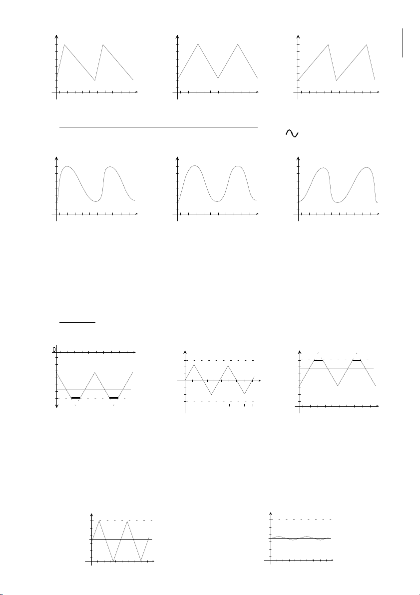
Signal sinusoïdal : distorsion harmonique : toutes harmoniques inférieures à -30dB.
Signal carré : temps de montée et de descente de 75ns max.
Signal triangulaire : non-linéarité inférieure à 1% (jusqu'à 100KHz)
Rapport cyclique : calibré à 50%
réglable de 20% à 80% continûement sur toutes les formes d'ondes.
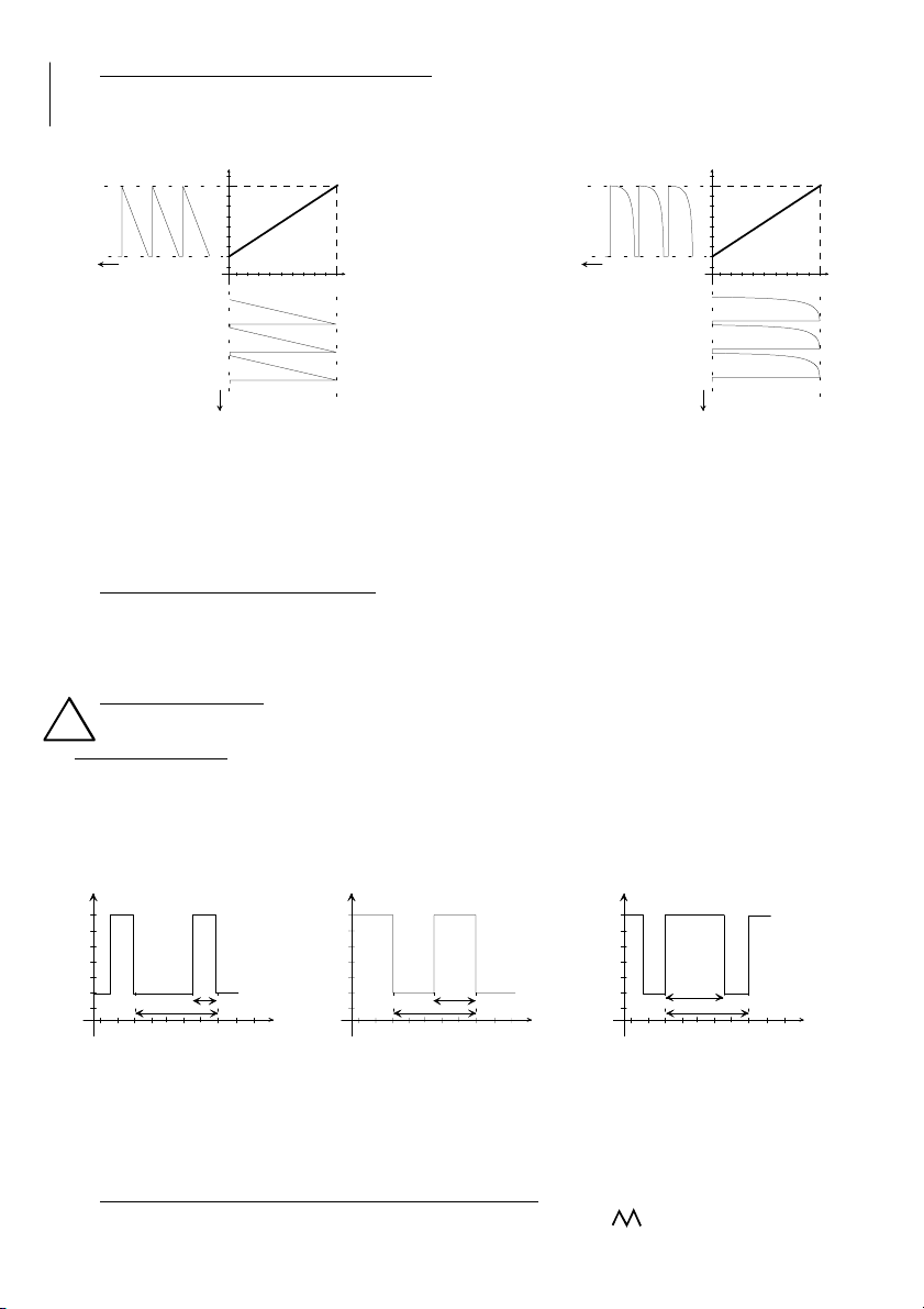
Balayage de fréquence : linéaire ou logarithmique disponible sur embase BNC, niveau 1V sur 35KΩ
interne période de la rampe : 5s à 10ms
profondeur de balayage : 1 à 100
Commande extérieure : impédance d'entrée : 47KΩ- Embase BNC
de fréquence tension de commande : ±10V pour une variation en fréquence de ±100
tension maximum admissible : ±30 V
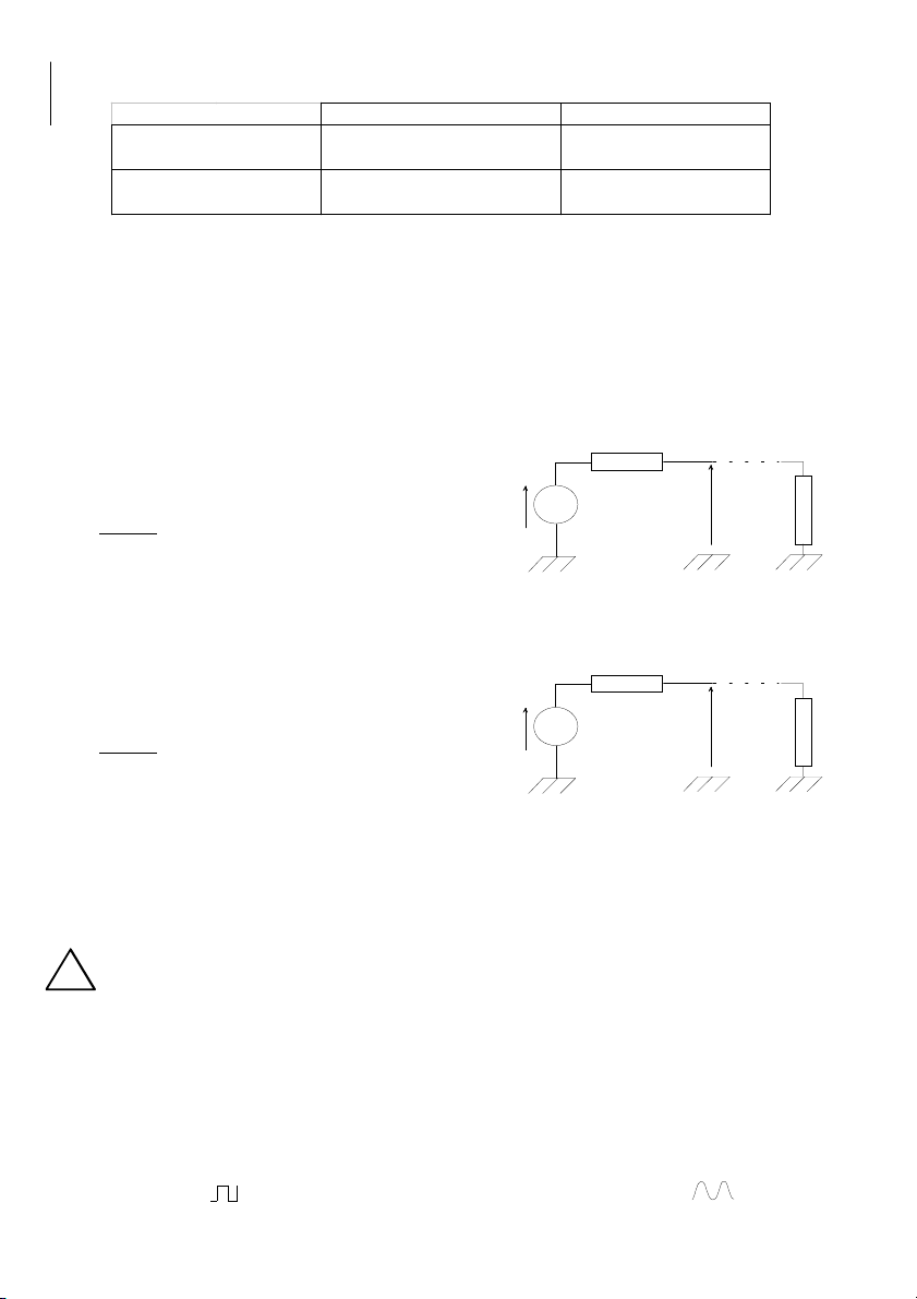
Sortie 50 Ω: supporte les courts-circuits permanents - Embase BNC
Amplitude réglable de : 0 à 20 V crête à crête à vide
0 à 10 V crête à crête sur 50W de charge
Variation d'amplitude : ±0.4dB de 0.2 Hz à 2MHz
Atténuateur : fixe : 0 dB, -20dB commutable
variable de 0 à -40dB (total -60dB).
Tension de décalage : indépendante des atténuateurs de sortie
calibré à 0V ± 10mV
variable de ± 10V à vide, de ± 5V sur 50Ωde charge
Protection de la sortie 50Ω: tension maximale en réinjection ±60Volts crête
Sortie 1Ω: supporte les courts-circuits permanents - Douilles de sécurité Ø4mm
impédance de sortie : 1Ω
puissance de sortie : 10W sinus sur une charge de 4 Ohms
tension max. de sortie : ±10 volts
courant max. de sortie : 1,7 A
bande passante (P = 10W) : 10 Hz 200 KHz
Les réglages d'amplitude, d'atténuation et de décalage en tension sont identiques à ceux de la sortie 50ΩΩ
ΩΩ
Ω
Protection de la sortie 1Ω: tension maximale en réinjection ±60Volts crête ; Intensité maximale 5A
Entrée extérieure : embase jack 3.5mm
commutation automatique dès connexion d'une fiche mâle jack 3.5mm
impédance d'entrée : 47KΩ
gain maximum : 40dB
bande passante : DC à 20 KHz
tension maximale avant saturation du préampli : 1 volt crête
tension maximale admissible : ±15 volts crête
Les réglages d'amplitude, d'atténuation et de décalage en tension sont identiques à ceux de la sortie 50ΩΩ
ΩΩ
Ω
Sortie TTL : supporte les courts-circuits permanents - Embase BNC
rapport cyclique fixe calibré à 50%
sortance > 10 - Temps de montée et de descente < à 50 ns.
Fréquencemètre : Plage de fréquence 0 à 20MHz avec commutation automatique
Affichage : 41/2 digits de 14mm
: 2 leds d'indication d'unité (MHz et KHz)
: Mesure de fréquence en interne ou sur entrée BNC
: Base de temps à quartz de 4MHz 50ppm
Entrée de mesure : Impédance 1MΩ// 30 pF
extérieure Sensibilité typique 5mV eff après une heure de fonctionnement
Tension maximale admissible 30V eff
AUTRES CARACTÉRISTIQUES
Alimentation : Secteur 230V ± 10% - 50/60Hz
FRANCAIS

- 5 -
4000 4 198 - 09/01
Entrée secteur : Embase «Europe CEE22»
Consommation : 90VA maxi
Encombrement : P = 250mm L = 220mm H (pieds repliés) = 105mm H (pieds dépliés) = 140mm
Masse : 3.2Kg
Conditions d’utilisation : +5°C à +40°C
Conditions de stockage : -10°C à +50°C
Conditions d’humidité : voir figure
Sécurité : Classe I
: Norme EN 61010-1 - Catégorie de surtension II degré de pollution 2
CEM : EN 55011 Groupe 1 Classe B, EN 50082-1 critère B
Accessoire livré : Cordon secteur 2 pôles + Terre
3- VUE D’ENSEMBLE (voir figure page 2)
3-1 ORGANES DE COMMANDES
1Réglage principal de fréquence 18 Réglage du niveau d'amplitude du signal
2Réglage fin de fréquence 19 Témoins de réinjection de tension
3Afficheurs à Led de 14mm et Leds d'unité de mesure 20 Sélecteur de réinitialisation de la protection
4Témoins de la gamme de fréquence sélectionnée 21 BNC sortie 50Ω
5Sélecteurs de la gamme de fréquence 22 BNC sortie TTL
6Réglage de la période de la rampe 23 BNC entrée/sortie contrôle de fréquence en tension
7Témoins du type de balayage sélectionné 24 BNC entrée mesure de fréquence
8Sélecteur du type de balayage 25 Témoins de mesure de fréquence extérieure
9Réglage de l'amplitude de la rampe 26 Sélecteurdemesuredefréquenceinterneouexterne
10 Réglage de la symétrie du signal (20% à 80%) 27 Sélecteur de type de signal
11 Témoin de réglage manuel de symétrie 28 Témoins de type de signal
12 Sélecteur du mode réglage de symétrie 29 Plaque signalétique
13 Sélecteur du mode de tension d'offset 30 Embase secteur Europe
14 Témoin de réglage manuel de la tension d'offset 31 Interrupteur Marche / Arrêt
15 Réglage de la tension continue d'offset 32 Entrée extérieure de signal
16 Sélecteur du mode d'atténuation 33 Témoins d'amplification du signal extérieur
17 Témoins de l'attenuation fixe de -20dB 34 Sortie 1Ω
4 - DESCRIPTION DES DIFFERENTES FONCTIONS
[1] REGLAGE PRINCIPAL DE FREQUENCE
Ce réglage permet de régler la fréquence depuis 0.02 x (multiplicateur de gamme [4]) jusqu'à 2 x (multiplicateur
de gamme [4]).
[2] REGLAGE FIN DE FREQUENCE 'FINE'
Ce réglage permet d'ajuster de ±10% la fréquence réglée avec le réglage principal [1].
[3] AFFICHAGE DE LA FREQUENCE
La lecture de la fréquence s'effectue grâce aux 5 afficheurs à leds et aux deux leds d'unité de mesure (MHz et
KHz) situées à droite des afficheurs.
[4] GAMMES DE FREQUENCE 'FREQUENCY'
[5] La sélection des gammes de fréquence s'effectue au moyen des deux sélecteurs repérés en [5].
Une impulsion sur le sélecteur [5] << déplace d'une gamme vers la gauche.
Une impulsion sur le sélecteur >> déplace d'une gamme vers la droite.
La gestion de gamme est bouclée sur elle-même :
- si le témoin 1M
Hz
est actif, l'appui sur le sélecteur >> sélectionnera la gamme 10
Hz
- si le témoin 10
Hz
est actif, l'appui sur le sélecteur << sélectionnera la gamme 1M
Hz.
[6] BALAYAGE EN FREQUENCE 'SWEEP'
[7] La sélection du mode de balayage en fréquence ('LIN', 'LOG', 'VCF') s'effectue au moyen du sélecteur [8].
[8] A chaque impulsion sur le sélecteur [8], le mode de balayage est modifié (LIN -> LOG -> VCF -> aucun).
[9] Le balayage en fréquence peut être vu comme un convertisseur tension -> fréquence.
[23] La fréquence de sortie n'est plus contrôlée par le bouton de réglage principal mais par une tension.
Cette tension peut être appliquée sur l'entrée BNC 'INPUT VCF' [23] ou générée en interne. Elle est disponible
en mode LIN et LOG sur la BNC 'INPUT/OUTPUT VCF' [23].
Le point de départ du balayage est donné par le réglage principal [1].
Caractéristique : Soit f0 la fréquence donnée par le réglage initial et fg la fréquence de fin de balayage.
f0<fg f0>fg
0Tension de balayage (Volts)
Fréquence (Hz)
fg
f0
10
Tension de balayage (Volt s)
fg
f0
Fréque nce (H z)
-10
FRANCAIS

- 6 -
4000 4 198 - 09/01
Balayage linéaire 'LIN' ou logarithmique 'LOG':
Le mode linéaire est actif lorsque le témoin [7] LIN est éclairé.
Le mode logarithmique lorsque le témoin [7] LOG est éclairé.
En interne, le GF 763AF génère une rampe ou un logarithme d'amplitude 10V. En appliquant cette rampe ou
ce logarithme sur la caractéristique précédente, on obtient les réponses en fréquence suivantes:
Ces deux formes de balayage ne fonctionnent que si f0 < fg.
Réglage de f0 : - désactiver tous les modes de balayage (témoins [7] éteints)
- régler f0 avec le bouton de réglage principal de fréquence [1]
- sélectionner le mode de balayage avec le sélecteur [8]
- ajuster la période de la rampe avec le réglage [6]
- ajuster l'amplitude de la rampe avec le réglage [9]
L'amplitude de la rampe donne la valeur de fg.
Fréquence contrôlée en tension ' VCF'
Lorsque le témoin [7] VCF est éclairé, la fréquence de sortie est contrôlée par la tension présente sur la fiche BNC [23].
Une variation de 0 à +10 volts sur l'entrée VCF fera varier la fréquence de sortie de f0 à f0 x 100. Cette excursion
de fréquence n'est possible que si le réglage principal [1] est réglé sur 0,02.
De même, une variation de 0 à -10 volts sur l'entrée VCF fera varier la fréquence de sortie de f0 à f0 /100.
Ce mode de balayage n'est possible que si le réglage principal [1]est réglé sur 2,0.
Equation caractéristique
F sortie = F0 x (1 +10 x Tension d'entrée VCF >0 ) ; F sortie = F0 / (1 - 10 x Tension d'entrée VCF <0)
La fiche BNC [23] est une entrée. La tension maximale admissible avant dégradation est de ± 30V.
Surcharge électrique : ne jamais appliquer sur les entrées, une tension qui excède les plages spécifiées.
[10] RAPPORT CYCLIQUE DU SIGNAL DE SORTIE 'SYMMETRY'
[11] Le sélecteur [12] permet de passer du mode calibré (témoin [11] éteint) en mode rapport cyclique variable et
[12] réglable par [10] (témoin [11] éclairé).
Il s'applique généralement aux signaux de type carré et permet de caractériser le temps à 'l'état haut' du signal
par rapport à sa période.
Lorsque le témoin[11] est éteint, le rapport cyclique est calibré à 50% (fig.2).
Le sélecteur [12] permet de passer du mode calibré au mode réglable (témoin [11] actif).
Lorsque le témoin [11] est actif, le rapport cyclique est réglable de 20% (butée gauche) à 80% (butée droite).
Il est donc possible de moduler la largeur du signal et ainsi générer des impulsions.
Les signaux des figures 1 et 3 ont respectivement des rapports cycliques de 30% et 70%.
Utilisation du rapport cyclique avec les signaux triangulaires
Lorsque le témoin [11] est actif et que le témoin [28] est en position Triangle , le réglage de symétrie [10]
modifie le signal triangulaire en dent de scie ou en rampe.
0Tension de balayag e (Volts)
Fréquen ce (Hz)
fg
f0
10
Temps
Temps
0Tension de balayag e (Volts)
Fréquen ce (Hz)
fg
f0
10
Temps
Temps
RAMPE LINEAIRE RAMPE LOGARITHMIQUE
!
0Temps (s)
Thaut
Période
Vsortie (V)
0.10.350.6
6V
2V
Rc = (∆Τ
haut / Péri o d e )
= ( 0. 6-0 .35)/( 0.6 -0 .1) x 100
= 50%
0Temps (s)
Tha ut
Période
Vsortie (V)
0.1 0.45 0.6
6V
2V
Rc = (∆Τ
haut / Péri od e )
= ( 0. 6-0 .45)/( 0.6 -0 .1) x 100
= 30%
0Temps (s)
Thaut
Période
Vsortie (V)
0.1 0.45 0.6
6V
2V
Rc = (∆Τ
haut / Péri o d e )
= ( 0.45 - 0.1)/(0.6-0 .1 ) * 100
= 70%
fig. 1 fig. 2 fig. 3
FRANCAIS

- 7 -
4000 4 198 - 09/01
Utilisation du rapport cyclique avec les signaux sinusoïdaux
Lorsque le témoin [11] est actif et que le témoin [28] est en position Sinus , le réglage de symétrie [10]
modifie le signal sinusoïdal comme indiquéci-dessous.
[13] TENSION CONTINUE DE DECALAGE 'DC OFFSET'
[14] Le sélecteur [13] permet de passer du mode tension d'offset calibré(témoin [14] éteint), au mode tension
[15] d'offset réglable par [15] (témoin [14] éclairé). En mode tension d'offset calibré(témoin [14] éteint), le signal
alternatif en sortie du générateur est centrésur 0V. En mode tension d'offset réglable (témoin [14] éclairé), le
réglage [15] permet d'ajouter, au signal alternatif, une tension continue réglable de -10 volts àvide (en butée
gauche) à+10 volts àvide (en butée droite).
Cette tension est entièrement indépendante des atténuateurs fixe [16] et variable [18].
Remarques
La tension crête de sortie de l'amplificateur est de ±10 volts. A ±11 volts, l'amplificateur sature. Pour obtenir
un signal correct en sortie, il est nécessaire de ne pas dépasser 10 volts en valeur absolue (offset+signal).
L'impédance de sortie du GF 763AF est de 50Ω. Si cette sortie est chargée par 50Ω, la résistance interne et la
charge forment un diviseur par 2 : l'excursion en tension sera de -5volts à+5volts.
De même, l'impédance de la sortie amplificateur [30] du GF 763AF est de 1Ω. Si cette sortie est chargée par
4Ω, la résistanceinterneetla charge forme un diviseur par 1,25 : l'excursion en tension sera de -8volts à+8volts.
[16] AMPLITUDE DE SORTIE ET ATTENUATEURS
[17] Le GF 763AF dispose de deux atténuateurs du signal de sortie. Le sélecteur [16] permet de passer du mode
[18] atténuation fixe 0dB (témoin [17] éteint), au mode atténuation fixe -20dB, diviseur par 10 (témoin [17] éclairé).
Le réglage [18] permet d'atténuer le signal de -40dB, en butée gauche (diviseur par 100), à0dB en butée droite
l'atténuation maximale est donc de -60dB (diviseur par 1000).
0Temps (s)
Vsortie (V)
6V
2V
0Temps (s)
Vsortie (V)
6V
2V
Réglage [10]
en butée gauche
Réglage [10]
en butée droite
0Temps (s)
Vsortie (V)
6V
2V
Réglage [10]
au centre ou calibré
0Temps (s)
Vsortie (V)
6V
2V
0Temps (s)
Vsortie (V)
6V
2V
0Temps (s)
Vsortie (V)
6V
2V
Réglage [10]
en butée gauche
Réglage [10]
en butée droite
Réglage [10]
au centre ou calibré
0Temps (s)
Vsortie (V)
+11V
Temps (s)
Vsortie (V)
-11V
Réglage [14]
en butée gauche
0Temps (s)
Vsortie (V)
+11V
-11V
Réglage [14]
au centre Réglage [14]
en butée droite
0Temps (s)
Vsort ie (V)
Atténuateur
fixe non activé
+10V
+5V
0Temps (s)
Vsort ie (V)
Atténuateur
fixe activé
+10V
+5V
FRANCAIS

- 8 -
4000 4 198 - 09/01
Lorsque la sortie [21] est connectée àune charge de 50Ω, l'amplitude de sortie est divisée par 2.
Lorsque la sortie [30] est connectée àune charge 4Ω, l'amplitude de sortie est divisée par 1,25.
[19] PROTECTION CONTRE LES REINJECTIONS DE TENSION
[20] Le générateur GF 763AF dispose d'une protection détectant les réinjections de tensions susceptibles
d'endommager l'étage de sortie de l'appareil.
Dès que le courant sur la sortie [21] et [34] dépasse le seuil limite de fonctionnement de l'étage de sortie, la
protection déconnecte instantanément les sorties [21] et [34] de l'amplificateur interne.
Le témoin [19] s'éclaire et signale un défaut. Après avoir suppriméle défaut, une impulsion sur le sélecteur [20]
permet de réinitialiser les sorties [21] et [34].
Si le défaut n'a pas étésupprimé, la protection se réengagera immédiatement.
Sur la sortie [20], la tension maximale admissible en réinjection est de ±60 volts crête.
Sur la sortie [34], la tension maximale admissible en réinjection est de ±60 volts crête ou 5 ampères crête.
[21] SORTIE BNC 50Ω
Le signal de sortie du générateur est disponible sur le connecteur BNC femelle [21].
L'impédance interne Zo est égale à50Ω.
Elle forme avec l'impédance Zi de l'étage connectée
en sortie, un atténuateur de rapport Zi / (Zo + Zi)
exemple : Vs mesuréàvide = Vg = 10 V crête àcrête
avec Zi = 50Ωnous avons :
Vs = 10x (50 / (50 + 50) = 5 V crête àcrête
Cette sortie peut être soumise àun court-circuit continu sans dommage pour l'appareil. (voir [19-20])
[34] SORTIE1Ω
Le signal de sortie du générateur est disponible entre les deux douilles de sécurité[34].
L'impédance interne Zo est égale à1Ω.
Elle forme avec l'impédance Zi de l'étage connectée
en sortie, un atténuateur de rapport Zi / (Zo + Zi)
exemple : Vs mesuréàvide = Vg = 10 V crête àcrête
avec Zi = 4Ωnous avons :
Vs = 10x 4 / (1 + 4) = 8 V crête àcrête
Cette sortie peut être soumise àun court-circuit continu sans dommage pour l'appareil. (voir [19-20])
[22] SORTIE TTL
Le signal de sortie TTL du générateur est disponible sur le connecteur BNC femelle [22].
Il est de forme carréet compatible avec les portes logiques TTL. Son amplitude est indépendante du réglage
[18] et son rapport cyclique est constant. Seule la fréquence est identique au signal de sortie.
Cette sortie peut être soumise àun court-circuit continu sans dommage pour l'appareil. Néanmoins en cas de
court-circuit, la fréquence interne du générateur ne pourra être visualisée sur l'afficheur [3].
Ceci est une sortie : toutes réinjections de tension risqueraient d'endommager l'appareil.
[24] MESURE DE FREQUENCE EXTERNE
[25] Lorsque le témoin [25] est éteint, l'afficheur [3] indique la fréquence du signal du générateur.
[26] En appuyant sur le sélecteur [26], la mesure de fréquence s'effectue sur l'entrée extérieure [24] et le témoin [25]
s'éclaire. La tension maximale admissible sur l'entrée [24] est de 30 Volts efficaces.
[27] TYPE DE SIGNAL
[28] Le sélecteur du type de SIGNAL [27] permet de sélectionner une des trois formes d'onde : sinus, triangle, carré.
Une impulsion sur le sélecteur [27] déplace d'une fonction vers la droite.
La gestion du type de fonction est bouclée sur elle-même :
si le témoin [28] est actif, l'appui sur le sélecteur [27] sélectionnera la fonction sinus .
[32] ENTREE EXTERIEURE DE SIGNAL 'EXT INPUT'
Amplitude maximale
200 mvolts crête àcrête 20 mvolts crête àcrête
2 volts crête àcrête20 volts crête àcrête
Atténuateur fixe désactivé Atténuateur fixe activé
Amplitude minimale
Z0
Vg Vs Z
i
Z0
Vg Vs Z
i
!
FRANCAIS

- 9 -
4000 4 198 - 09/01
[33] Le GF 763AF dispose d'une entrée pour un signal extérieur. Dès l'insertion d'un jack mâle, une commutation
automatique déconnecte le signal du générateur de l'amplificateur et le remplace par le signal entrésur [32]. Le
témoin [33] s'éclaire. Le gain maximum est de 40dB ( x 100). Les réglages d'amplitude, d'atténuation et de
décalage en tension agissent toujours sur le signal amplifiéprésent sur les sorties [21] et [34] .
L'embase jack 3.5mm [32] est une entrée. La tension maximale admissible avant dégradation est de ± 15V.
Surchargeélectrique : ne jamaisappliquer sur les entrées, une tension qui excède lesplages spécifiées.
[30] EMBASE SECTEUR AVEC PORTE FUSIBLE.
Cette embase reçoit le cordon d'alimentation. Le porte fusible est muni d'un fusible 5x20 T630mA.
[31] INTERRUPTEUR O - I
Interrupteur enfoncédu côtéO : l'appareil est arrêté.
Interrupteur enfoncédu côtéI : l'appareil est en fonctionnement.
5 - FONCTIONNEMENT
5-1 MONTAGE ET MISE EN PLACE DE L’APPAREIL
Le générateur doit reposer sur ses 2 butées caoutchouc arrières ainsi que sur ses 2 pieds-béquilles avants (repliés
ou entièrement dépliés).
Brancher le cordon secteur dans l’embase [30] àl’arrière de l’appareil.
Brancher l'autre extrémitédu cordon dans un socle de prise. Votre appareil est prêt àfonctionner.
5-2 UTILISATION
Appuyer sur Ide l'interrupteur Marche-Arrêt [31] : les témoins [3],[4] et [28] s'allument.
La configuration par défaut du générateur est la suivante :
- Fonction : sinus - Gamme de fréquence : 10KHz
- Balayage de fréquence : inactif - Symétrie du signal : calibrée à50%
- Décalage en tension : calibréà0 volt
Le signal est alors disponible sur la BNC 50Ω[21], sur la sortie amplifiée [34] et sous forme logique sur [22].
Un temps de chauffe de 30 minutes est nécéssaire pour atteindre les spécifications annoncées.
Sélectionner :
- la forme du signal avec [27] - la gamme de fréquence avec [5]
- le mode de balayage avec [8] - le mode de symétrie calibréou variable avec [12]
- le mode de décalage en tension continue avec [13] - l'atténuateur fixe de -20dB avec [16]
Régler :
- la fréquence avec [1] et [2] - la période de la rampe avec [6]
- l'amplitude de la rampe avec [9] - la symétrie du signal avec [10]
- la tension continue de décalage avec [15]
CONSEILS: Pour un signal d'amplitude inférieure à1 V crête àcrête, utiliser l'atténuateur -20 dB, le réglage
d'amplitude en sera facilité.
PRECAUTION:Réglerl'amplitudedu signal afin de rester au-dessous de latensionmaximum acceptéepar la charge.
6 - EXEMPLES D'APPLICATIONS
6-1 RÉPONSE EN FRÉQUENCE D'UN AMPLIFICATEUR
Connecter la sortie du générateur de fonctions àl'entrée de l'amplificateur àtester après avoir régléconvenablement
l'amplitude. Sur la sortie correctement chargée, visualiser le signal sur un oscilloscope. Faire varier la fréquence en
notant la variation de la tension Vs par rappport àla tension d'entrée Ve. Ce rapport sera en dB : 20 Log Vs
Ve
La fréquence de coupure à-3dB sera atteinte lorsque, Ve restant constante,
Vs aura diminuédans un rapport de √2 soit 1,414.
Un signal carrésur l'entrée de l'ampli permet de visualiser en sortie des défauts tels que : dépassement,
rebondissement, temps de montée ...
Un signal triangulaire donne, mieux qu'une sinusoïde, le niveau maximum avant apparition de l'écrêtage.
6-2 AMPLIFICATEUR ÀTRANSISTOR SANS ALIMENTATION EXTERIEURE
Régler la tension d'alimentation du montage avec le bouton de réglage d'offset [15].
Activer l'atténuateur -20dB. Régler la forme, la fréquence et l'amplitude du signal.
Connecter la sortie du générateur en Ve.
!
Vcc
Vcc
Ve
FRANCAIS

- 10 -
4000 4 198 - 09/01
6-3 RÉPONSE EN FRÉQUENCE :
Le signal d'un deuxième générateur de fonctions ou plus simplement la tension de balayage en dent de scie d'un
oscilloscope appliquéàl'entrée VCF [23], provoquent un balayage en fréquence. Un oscilloscope connectéen sortie
de l'étage àtester visualise automatiquement la courbe de réponse.
6-4 SEUILS DE COMMUTATION :
Pour tester en dynamique les niveaux de commutation de comparateurs ou de différentes familles logiques, on
utilisera un signal triangulaire de basse fréquence d'amplitude et d'offset adaptés.
6-5 ANALYSE DE SYSTÈMES :
L'utilisationdesignaux carrés, triangulaires ou sinusoïdaux en bassefréquencesert àanalyser des asservissements.
On met en évidence : erreur statique, linéarité, précision, rapidité, stabilité...
6-6 RÉPONSE EN FRÉQUENCE D'UNE ENCEINTE ACOUSTIQUE
Il est possible de tracer la courbe de réponse en fréquence d'une enceinte en connectant celle-ci sur la sortie HP.
Un capteur acoustique positionnédevant le haut-parleur restituera l'amplitude du signal reçu.
7 - MAINTENANCE
Aucunentretien particulier n’est àenvisager pour cet appareil.Eviter la poussière, l’humidité, les chocs, votreappareil
vous en sera reconnaissant. Pour le nettoyage, utiliser un chiffon doux àpoussière.
Si les témoins [3], [4] et [24] ne s'éclairent pas àla mise sous tension, vérifier :
- si l'interrupteur Marche - Arrêt est activé- la présence de la tension secteur
- le raccordement au réseau - le fusible de protection (T630mA)
8 - SERVICE APRES-VENTE
Le service après-vente est assurépar la sociétéelc.
La période de garantie est de un an pièces et main d’oeuvre. Ne sont toutefois pas garantis les pannes ou défauts
provenantd’unemauvaiseutilisation de l’appareil (tension secteur non conforme, chocs...)ouayant étéd épannéhors
de nos services ou des ateliers agréés de nos agences.
9 - DECLARATION DE CONFORMITE
suivant l’ISO/IEC guide 22 et l’EN45014
Fabricant : ELC
Adresse : 59, avenue des Romains 74000 Annecy France
déclare que le produit
Nom : Générateur de fonctions
Type : GF 763AF
est conforme aux spécifications suivantes :
Sécurité: IEC1010-1:1990 + A1 / EN61010-1:1993 + A2:1995
Classe I, Catégorie de surtension II, degréde pollution 2.
CEM : CISPR11:1990 / EN55011:1991 - Groupe 1 Classe B
EN50082-1:1998 critère d’aptitude B
EN 61000.4.2 : 1995 - 8KV AD
EN 61000.4.3 : 1996 - 3V/m
ENV 50204 : 1995
EN 61000.4.4 : 1995 - 1KV sur l’alimentation
EN 61000.4.5 : 1995 - 1KV mode différentiel - 2KV mode commun
EN 61000.4.6 : 1996 - 3V
EN 61000.4.11 : 1994
Informations complémentaires :
Le produit ci-dessus est conforme aux exigences de la Directive Basse Tension 73/23/CEE, de la Directive
CompatibilitéElectromagnétique 89/336/CEE et de la directive 93/68/CEE.
Annecy, le 07/03/2000
Henri Curri, Gérant
FRANCAIS

- 11 -
4000 4 198 - 09/01
!
TABLE OF CONTENTS
1 - PRELIMINARY INFORMATION..............................................................
Page 11
1-1 INTRODUCTION ...............................................................................................
Page 11
1-2 SAFETY INSTRUCTIONS .................................................................................
Page 11
1-3 SYMBOLS AND DEFINITIONS .........................................................................
Page 11
2 - PRELIMINARY INSTRUCTIONS ..........................................................
Page 12
2-1 PACKAGING ......................................................................................................
Page 12
2-2 TECHNICAL SPECIFICATIONS .......................................................................
Page 12
3 - CONTROLS DESCRIPTION ..................................................................
Page 13
3-1 CONTROLS .......................................................................................................
Page 13
4 - DESCRIPTION OF THE DIFFERENT FUNCTIONS ..............................
Page 13
5 - WORKING ...............................................................................................
Page 17
5-1 MOUNTING AND PLACING OF THE INSTRUMENT .......................................
Page 17
5-2 USE ....................................................................................................................
Page 17
6 - EXAMPLES OF APPLICATIONS ...........................................................
Page 17
6-1 TRANSFER FUNCTION OF AN AMPLIFIER ....................................................
Page 17
6-2 TRANSISTOR AMPLIFIER WITHOUT EXTERNAL FEEDING ........................
Page 17
6-3 TRANSFER FUNCTION ....................................................................................
Page 18
6-4 SWITCHING THRESHOLDS .............................................................................
Page 18
6-5 SYSTEMS ANALYSIS .......................................................................................
Page 18
7 - MAINTENANCE ......................................................................................
Page 18
8 - AFTER SALES SERVICE ......................................................................
Page 18
9 - DECLARATION OF CONFORMITY .......................................................
Page 18
1 - PRELIMINARY INFORMATION
1-1 INTRODUCTION
You just bought the CENTRAD* FUNCTIONS GENERATOR type GF 763AF. We thank you and congratulate you for
your good choice. elc proposes also many electronic test instruments : POWER SUPPLIES, FREQUENCY METER, PANEL
METERS, DECADE BOXES ...
*CENTRAD is a registered trademark of the elc company.
Manufacturer : elc 59, avenue des Romains 74000 ANNECY - FRANCE
Phone : +33 (0)4 50 57 30 46 Fax : +33 (0)4 50 57 45 19
Instrument : FUNCTIONS GENERATOR
Trademark : CENTRAD
Type : GF 763AF
Mains supply : 230V AC 50/60 Hz
1.2 SAFETY INSTRUCTIONS
No intervention is authorized inside the casing.
The instrument must be used according to the instructions of this manual.
Theplugof the feeding cable being usedasthe switch off device, the instrumentmustbe connected to a mains
socket (230V 50/60Hz) easily accessible, which has an earth connection.
When the instrument has to be powered by an autotransformer, in order to get a voltage reduction, to make
sure that the common terminal is connected to the earthed pole of the feeding circuit.
Electric overload : do never apply, to the inputs, a voltage exceeding the specified ranges.
1-3 SYMBOLS AND DEFINITIONS
You will find following symbols on the instruments :
CAUTION ! RISK OF EARTH TERMINAL CAUTION ! TO REFER TO
ELECTRIC SHOCK THE MANUAL
ENGLISH

- 12 -
4000 4 198 - 09/01
2 - PRELIMINARY INSTRUCTIONS
2-1 PACKAGING
The packing material of the functions generator GF 763AF is intended to protect it during its transport.
Keep them, they may be useful later on.
Packing list
1 instructions manual 1 plastic protecting bag 1 functions generator GF 763AF
2 cardboard packing pieces 1 mains cord
2-2 TECHNICAL SPECIFICATIONS
Frequency range : 0.2 Hz to 2 MHz in 6 ranges.
Setting : separate vernier of frequency + fine setting.
Drift : 0.2% in 8 hours (after 30 minutes of working)
Sine wave : harmonic distortion : every harmonic below -30dB.
Square wave : rise and fall time of 75ns maxi.
Triangular wave : non-linearity below 1% (up to 100KHz)
Cyclic ratio : calibrated at 50%
adjustable from 20% to 80% continuously for all wave forms.
Frequency's internal sweep : linear or logarithmic available at the BNC socket, 1V level with 35KΩ
period of the saw tooth signal : 5s to 10ms
sweep depth : 1 to 100
Frequency's external control : input impedance : 47KΩ- BNC socket
control voltage : ±10V for a frequency variation of ±100
maximum permissible voltage : ±30 V
50 Ωoutput : stands steady short-circuits - BNC socket
Amplitude adjustable from : 0 to 20 V peak to peak without load
0 to 10 V peak to peak with a 50Ωload
Amplitude variation : ±0.4dB from 0.2 Hz to 2 MHz
Attenuator : fixed : 0 dB, -20dB switchable
variable from 0 to -40dB (total -60dB).
Offset voltage : independent of the output attenuators
calibrated at 0V ± 10mV
variable of ± 10V without load, of ± 5V with a 50Ωload
Protection of the 50Ωoutput : maximum voltage on reinjection ±60Volts peak
1Ωoutput : stands steady short-circuits - Ø4 mm safety sockets
1Ωoutput impedance
output power : 10W sine wave with a 4Ωload
maxi output voltage : ± 10 Volts
maxi output current : 1.7A
bandwidth (P = 10W) : 10 Hz to 200 KHz
The adjustments of amplitude, attenuation and voltage offset are identical with those of the 50Ωoutput
Protection of the 1Ωoutput : maximum voltage on reinjection ± 60 Volts peak ; maximum current 5A
External input : 3.5 mm jack socket
automatic switching immediately on connection of a 3.5mm jack male plug
input impedance 47 KΩ
maximum gain : 40 dB
bandwidth : DC to 20 KHz
maximum voltage before saturation of the preamplifier : 1 Volt peak
maximum permissible voltage : ± 15 Volts peak
The adjustments of amplitude, attenuation and voltage offset are identical with those of the 50ΩΩ
ΩΩ
Ωoutput
TTL output : stands steady short-circuits - BNC socket
fixed cyclic ratio calibrated at 50%
fan out > 10 - Rise and fall time < 50 ns.
Frequency meter : Frequency range from 0 to 20 MHz autoscale
Display : 41/2 digits (Leds of 14mm)
2 Leds for the units display (MHz & KHz)
Frequency measurement from generator's output or with BNC input
Quartz time base of 4 MHz, thermal drift : ± 50 ppm
Input for external measurement : Impedance 1 MΩ// 30 pF
Typical sensitivity of 5 mV rms after one working hour
Maximum permissible voltage of 30 V rms.
OTHER SPECIFICATIONS
Feeding : mains 230V ± 10% - 50/60Hz
ENGLISH

- 13 -
4000 4 198 - 09/01
Mains input : «Europe CEE22»receptacle
Consumption : 90VA maxi
Dimensions : D = 250mm L = 220mm H (folded feet) = 105mm H (unfolded feet) = 140mm
Weight : 3.2Kg
Conditions of use : +5°C to +40°C
Conditions of storage : -10°C to +50°C
Conditions of humidity : see graph
Safety : Class I
: EN 61010-1 standard - overvoltage category II, pollution degree 2
EMC : EN 55011 Group 1 Class B, EN 50082-1 criterion B
Accessory supplied : bipolar + earthed mains cord
3 - CONTROLS DESCRIPTION (See drawing page 2)
3-1 CONTROLS
1Frequency's main setting 18 Setting of the signal's amplitude level
2Frequency's fine setting 19 Warning Leds of voltage reinjection
3Indicator with 14 mm Leds & Leds for units of measur. 20 Selector of protection's resetting
4Warning Leds of the selected frequency range 21 BNC socket "50Ωoutput"
5Selectors of frequency range 22 BNC socket "TTL output"
6Setting of the saw tooth period 23 BNCsocket"input/output monitoring of frequency"
7Warning Leds of the selected sweep type 24 BNC socket "input frequency measurement"
8Selector of sweep type 25 WarningLeds of external frequency measurement
9Setting of the saw tooth amplitude 26 Selector of internal or external frequency measur.
10 Setting of the signal's symmetry (20% to 80%) 27 Selector of signal's type
11 Warning Led of symmetry's manual setting 28 Warning Leds of signal's type
12 Selector of the mode "symmetry setting" 29 Description plate
13 Selector of the mode "offset voltage" 30 Europe mains receptacle
14 Warning Led of manual setting of the offset voltage 31 On/Off switch
15 Setting of the offset DC-voltage 32 Signal's external input
16 Selector of attenuation mode 33 Amplification warning Leds of external signal
17 Warning Leds of the -20dB fixed attenuation 34 1Ωoutput
4 - DESCRIPTION OF THE DIFFERENT FUNCTIONS
[1] FREQUENCY'S MAIN SETTING
It allows to adjust the frequency from 0.02 x (range multiplier [4]) up to 2 x (range multiplier [4]).
[2] FREQUENCY'S FINE SETTING 'FINE'
It allows to adjust of ±10% the frequency set with the main setting [1].
[3] FREQUENCY'S DISPLAY
The frequency can be read thanks to a Led-indicator (5 digits), and to 2 Leds for the units of measurement (MHz
and KHz) on the right of the indicator.
[4] FREQUENCY RANGES 'FREQUENCY'
[5] The frequency ranges are selected by means of 2 selectors [5].
The selector [5] << selects the next range towards the left.
The selector [5] >> selects the next range towards the right.
When the "1MHz" Led is on and you press the selector >>, the next selected range is 10Hz
When the "10Hz" Led is on and you press the selector <<, the next selected range is 1MHz
.
[6] FREQUENCY SWEEP 'SWEEP'
[7] The mode of frequency sweep ('LIN', 'LOG', 'VCF') is selected by means of the selector [8].
[8] Each pressure on the selector [8] modifies the sweep mode (LIN -> LOG -> VCF -> none).
[9] The frequency sweep can be considered as a voltage -> frequency convertor.
[23] The output frequency is not more monitored by the main setting's knob, but by a voltage.
This voltage can be applied to the 'INPUT VCF' BNC input [23] or generated internally. It is available with the
LIN and LOG modes at the 'INPUT/OUTPUT VCF' BNC socket [23].
The starting point of the sweep is given by the main setting [1].
Characteristic : let f0 be the frequency given by the initial setting and fg the frequency of end of sweep.
f0<fg f0>fg
0
Sweep voltage (Volts)
Frequency (H z)
fg
f0
10
Sweep voltage (Volts)
fg
f0
Frequency (Hz)
-10
ENGLISH

- 14 -
4000 4 198 - 09/01
!
Linear 'LIN' or logarithmic 'LOG' sweep :
The linear mode works, when the Led [7] LIN is lightening.
The logarithmic mode works, when the Led [7] LOG is lightening.
Internally, the generator GF 763F generates a saw tooth signal or a logarithm of 10V amplitude. While applying
it to the previous characteristic, the following transfer functions are obtained :
These two sweep forms only work when f0 < fg.
Adjustment of f0 : - to press off all sweep modes (Leds [7] out)
- to adjust f0 with the knob of frequency's main setting [1]
- to select the sweep mode with the selector [8]
- to adjust the period of the saw tooth signal with the setting knob [6]
- to adjust the amplitude of the saw tooth signal with the setting knob [9]
The amplitude of the saw tooth signal gives the fg value.
Voltage controlled frequency 'VCF'
When the Led [7] VCF is lightening, the output frequency is monitored by the voltage available at the BNC socket [23].
A variation from 0 to +10 Volts at the VCF input varies the output frequency from f0 to f0 x 100.
This frequency range is only possible, when the main setting knob [1] is set at 0.02.
In the same way, a variation from 0 to -10V at the VCF input varies the output frequency from f0 to f0 /100.
This sweep mode is only possible, when the main setting knob [1] is set at 2.0.
Characteristic equation
Output frequency = F0 x (1 +10 x VCF input voltage > 0 ) ; Out. Freq. = F0 / (1 - 10 x VCF input voltage < 0)
The BNC socket [23] is an input. The maximum permissible voltage before damage is ± 30V.
Electric overload : do never apply to the inputs, a voltage exceeding the specified ranges.
[10] CYCLIC RATIO OF THE OUTPUT SIGNAL 'SYMMETRY'
[11] The selector [12] allows to change over from the calibrated mode (Led [11] out) to the mode "variable
[12] cyclic ratio and adjustable by [10]" (Led [11] lightening).
It applies generally to square signals and allows to give the ratio of the time (at the top position) of the
signal compared with its period.
When the Led [11] is out, the cyclic ratio is calibrated at 50% (diagram 2).
The selector [12] allows to change over from the calibrated mode to the adjustable mode (Led [11] on).
When the Led [11] is on, the cyclic ratio is adjustable from 20% (knob at the left stop) to 80% (knob at the right
stop). Thus, it is possible to modulate the signal width and to generate pulses.
The signals of the diagrams 1 and 3 have respective cyclic ratios of 30% and 70%.
Use of the cyclic ratio with triangular signals
When the Led [11] and the Led [28] are on, the symmetry's setting knob [10] modifies the triangular signal
in saw tooth signal.
LINEAR SAW TOOTH
SIGNAL
LOGARITHMIC SAWTOOTH
SIGNAL
0Time (s)
Time (top)
Peri od
Output (V)
0.10.350.6
6V
2V
Rc = (∆Tim e (at th e top) / Per io d)
= (0. 6-0.35) /(0.6 -0 .1)x100
= 50%
0Time (s)
Time (top)
Peri od
Output (V)
0.1 0.45 0.6
6V
2V
Rc = (∆ T im e (at the top ) / Period)
= (0. 6-0.45) /(0.6 -0 .1)x100
= 30%
0Time (s)
Time (top)
Peri od
Output (V)
0.1 0.45 0.6
6V
2V
Rc = (∆T im e (at the top) / Perio d)
= (0.4 5-0.1) /(0.6- 0.1 ) * 100
= 70%
Diagram 1 Diagram 2 Diagram 3
0Sweep voltage (Volts)
Frequency (Hz)
fg
f0
10
Time
Time
0Sweep voltage (Volts)
Frequency (Hz)
fg
f0
10
Time
Time
ENGLISH

- 15 -
4000 4 198 - 09/01
Use of the cyclic ratio with sine signals
When the Led [11] and the Led [28] are on, the symmetry's setting knob [10] modifies the sine signal as
drawn hereunder.
[13] OFFSET DC-VOLTAGE 'DC OFFSET'
[14] The selector [13] allows to change over from the mode "calibrated offset voltage" (Led [14] out) to the mode
[15] "offset voltage adjustable by [15]" (Led [14] on). In the mode "calibrated offset voltage" (Led [14] out), the output
AC-signal of the generator is set at 0V. In the mode "adjustable offset voltage" (Led [14] on), the setting knob
[15] allows to add to the AC-signal, a DC-voltage adjustable from -10 Volts without load (knob at the left stop)
to +10 Volts without load (knob at the right stop).
This voltage is entirely independent of the fixed [16] and variable [18] attenuators.
Remarks
The output peak voltage of the amplifier is ±10V. The amplifier reaches the saturation point at ±11V. In order to
obtain an accurate output signal, it is necessary not to exceed 10V as absolute value (offset+signal).
The output impedance of the GF 763AF is 50Ω. If this output has a 50Ωload, internal resistance and load make
a divider by 2 : the voltage will range from -5 Volts to +5 Volts.
In the same way, the impedance of the amplifier output [30] of the GF 763AF is 1W. If this output has a 4Ωload,
internal resistance and load make a divider by 1.25 : the voltage will range from -8 Volts to +8 Volts.
[16] OUTPUT AMPLITUDE AND ATTENUATORS
[17] The GF 763AF is fitted with 2 attenuators of the output signal.
[18] The selector [16] allows to change over from the mode "0dB fixed attenuation" (Led [17] out) to the mode -20dB
fixed attenuation, divider by 10" (Led [17] on).
The setting knob [18] allows to attenuate the
signal from -40dB, when knob at the left stop
(divider by 100) to 0dB, when knob at the right
stop : the maximum attenuation is thus-60dB
(divider by 1000).
0Time (s)
Output (V)
6V
2V
0Time (s)
Output (V)
6V
2V
Setting [10]
with knob at the l eft stop
Setting [10]
with knob at the ri
g
ht stop
0Time (s)
Output (V)
6V
2V
Setting [10] with knob
in the middle or calib rated
0Time (s)
Output (V)
6V
2V
0Time (s)
Output (V)
6V
2V
0Time (s)
Output (V)
6V
2V
Setting [10]
with knob at the l eft stop
Setting [10]
with knob at the right stop
Setting [10] with knob
in the middle or calib rated
0Time (s)
Output (V)
+11V
Time (s)
Output (V)
-11V
Setting 14
with knob at the left stop
0Time (s)
Output (V)
+11V
-11V
Setting 14
with knob in the middle Setting 14
with k no b at the right stop
0Time (s)
Output (V)
Fixed attenuator
switched off
+10V
+5V
0Time (s)
Output (V)
Fixed attenuator
switched on
+10V
+5V
ENGLISH

- 16 -
4000 4 198 - 09/01
Z0
Vg Vs Z
i
Z0
Vg Vs Z
i
!
When the output [21] is connected to a 50Ωload, the output amplitude is divided by 2.
When the output [30] is connected to a 4
ENGLISHENGLISH
load, the output amplitude is divided by 1.25.
[19] PROTECTION AGAINST VOLTAGE REINJECTIONS
[20] The generator GF 763AF is fitted with a protection detecting voltage reinjections, which are likely to damage the
output stage of the instrument.
As soon as the current at the output [21] or [34] exceeds the maximum working threshold of the output stage,
the protection disconnects instantaneously the outputs [21] and [34] of the internal amplifier.
The Led [19] lights up and warns of a fault. After the fault has been cleared, a pressure on the selector [20] allows
to reset the outputs [21] and [34].
If the fault has not been cleared, the protection will operate again immediately.
At the output [20], the maximum permissible voltage on reinjection is ±60 Volts peak.
At the output [34], the maxi. permissible voltage on reinjection is ±60 Volts peak or 5 Amperes peak.
[21] 50ΩBNC OUTPUT
The output signal of the generator is available at the female BNC connector [21].
The internal impedance Zo isequal to 50Ω.
With the impedance Zi of the output connected stage,
it makes an attenuator with ratio Zi / (Zo + Zi).
example : Vs measured without load = Vg = 10 V peak to peak
with Zi = 50Ω, we obtain :
Vs = 10x (50 / (50 + 50) = 5 V peak to peak.
This output can stand a steady short-circuit without damage for the instrument. (see [19-20])
[34] 1ΩOUTPUT
The output signal of the generator is available between both safety sockets [34].
The internal impedance Zo is equal to 1Ω.
With the impedance Zi of the output connected stage,
it makes an attenuator with ratio Zi / (Zo + Zi)
example : Vs measured without load = Vg = 10 V peak to peak
with Zi = 4Ω, we obtain :
Vs = 10x 4 / (1 + 4) = 8 V peak to peak.
This output can stand a steady short-circuit without damage for the instrument. (see [19-20])
[22] TTL OUTPUT
The TTL output signal of the generator is available at the female BNC connector [22].
It is square-shaped and TTL-compliant. Its amplitude is independent of the setting [18] and its cyclic ratio is
constant. Merely the frequency is identical with the output signal.
Thisoutput can stand a steadyshort-circuit without damage for the instrument. Nevertheless, in case of short-
circuit, the generator's internal frequency can not be read on the indicator [3].
This is an output : every voltage reinjection might damage the instrument.
[24] MEASUREMENT OF EXTERNAL FREQUENCY
[25] When the warning Led [25] is out, the indicator [3] shows the frequency of the generator's signal.
[26] Onpressing the selector [26], the frequencyis measured at the external input[24] and the warning Led [25]lights
up. The maximum permissible voltage at the input [24] is 30 Volts rms.
[27] SIGNAL TYPE
[28] The selector of signal type [27] allows to select one of the 3 wave forms : sine, triangle, square.
A pressure on the selector [27] displaces to the next function towards the right.
If the Led [28] is on and you press the selector [27], the next selected function will be sine .
[32] SIGNAL'S EXTERNAL INPUT 'EXT INPUT'
Fixed attenuator switched off Fixed attenuator switched on
Minimum amplitude
Maximum amplitude
200 mVolts peak to peak 20 mVolts peak to peak
2 Volts peak to peak20 Volts peak to peak
ENGLISH

- 17 -
4000 4 198 - 09/01
!
Vcc
Vcc
Ve
[33] The GF 763AF is fitted with an input for an external signal. Immediately on the plugging in of a male jack, an
automatic switching disconnects the generator's signal from the amplifier and replaces it by the signal present
at [32]. The warning Led [33] lights up. The maximum gain is 40 dB (x100). The adjustments of amplitude,
attenuationandvoltageoffsethavealwaysan influence on the amplified signal present at the outputs[21]and[34].
The 3.5 mm jack socket [32] is an input. The maximum permissible voltage before damage is ± 15V.
Electric overload : do never apply to the inputs, a voltage exceeding the specified ranges.
[30] EUROPE MAINS RECEPTACLE
This receptacle is destined for the mains cord. The fuse-holder is fitted with a 5x20 fuse T630mA.
[31] ON/OFF SWITCH
Switch pressed on "O" : the instrument doesn't work.
Switch pressed on "I" : the instrument works.
5 - WORKING
5.1 MOUNTING AND PLACING OF THE INSTRUMENT
The generator must stand on its 2 back rubber thrusts as well as on its 2 front legs (folded or entirely unfolded).
To connect the mains cord in the receptacle [30] at the rear of the instrument.
To connect the other termination in a wall socket. Your instrument is ready to work.
5.2 USE
To press the On/Off switch on "I" [31] : the Leds [3], [4] and [28] light up.
Basically, the generator configuration is as follows :
- Function : sine - Frequency range : 10KHz
- Frequency sweep : not in action - Signal's symmetry : calibrated at 50%
- Voltage offset : calibrated at 0 Volt
The signal is then available at the 50W BNC socket [21], the amplified output [34] and in a logical form at [22].
A warm-up period of 30 minutes is necessary, in order to reach the announced specifications.
To select:
- the signal's form with [27] - the frequency range with [5]
- the sweep mode with [8] - the mode "calibrated or variable symmetry" with [12]
- the mode "DC-voltage offset" with [13] - the -20dB fixed attenuator with [16]
To adjust :
- the frequency with [1] and [2] - the saw tooth's period with [6]
- the saw tooth's amplitude with [9] - the signal's symmetry with [10]
- the offset DC-voltage with [15]
ADVICES : For a signal with an amplitude below 1 V peak to peak, use the -20 dB attenuator, the amplitude will be
set easier.
CAUTION : To set the signal amplitude, in order to remain under the maximum voltage accepted by the load.
6 - EXAMPLES OF APPLICATIONS
6-1TRANSFER FUNCTION OF AN AMPLIFIER
To connect the output of the functions generator to the input of the amplifier under test, after the amplitude has been
set properly. To load the output correctly and to display the signal on an oscilloscope. To vary the frequency, while
noting the variation of the Vs voltage compared with the Ve input voltage. This ratio will be in dB : 20 Log Vs
Ve
The -3dB cut-off frequency is reached, when Vs has decreased within a ratio of √2, that is 1.414,
with Ve remaining constant.
A square signal at the amplifier input allows to display faults in output, such as : overshoot, bouncing, rise time ...
Better than a sine wave, a triangular wave gives the maximum level before clipping.
6-2TRANSISTOR AMPLIFIER WITHOUT EXTERNAL FEEDING
To set the supply voltage of the mounting with the offset setting knob [15].
To switch the -20dB attenuator on.
To set the form, frequency and amplitude of the signal.
To connect the generator output to Ve.
ENGLISH

- 18 -
4000 4 198 - 09/01
6-3TRANSFER FUNCTION :
Thesignal of a second functions generatoror just the "saw tooth" sweepvoltage of an oscilloscope, appliedto the VCF
input [23], causes a frequency sweep. An oscilloscope connected to the output of the stage under test displays
automatically the response curve.
6-4 SWITCHINGTHRESHOLDS :
Forthe dynamic testing of the switchinglevels of comparators or of differentlogical families, a low frequency triangular
wave, of adapted amplitude and offset, will be used.
6-5 SYSTEMS ANALYSIS :
Square, triangular or sine waves in low frequency are used for the analysis of servo control systems. So, static error,
linearity, accuracy, rapidity, stability ... are brought out.
6-6TRANSFER FUNCTION OF AN ACOUSTIC ENCLOSURE
It is possible to draw the frequency response curve of an enclosure, while connecting it to the loudspeaker output. An
acoustic sensor positioned before the loudspeaker will reproduce the amplitude of the received signal.
7 - MAINTENANCE
No particular maintenance is required for this instrument. To avoid dust, humidity, shocks ; your instrument will be
grateful to you for that. For the cleaning, please use a smooth duster.
If the Leds [3], [4] and [24] do not light up on switching on, to check :
- if the "On/Off" switch is on - that mains voltage is available
- the connection to mains - the protection fuse (T630mA).
8 - AFTER SALES SERVICE
The after sales service is ensured by the elc company.
During one year, spare parts and workmanship are guaranteed. This guarantee does not apply to instruments
presenting faults or failures caused by an improper use (wrong mains voltage, shocks...) or which have been repaired
outside our factory or the repair shops of our authorized agencies.
9 - DECLARATION OF CONFORMITY
according to ISO/IEC guide 22 and EN45014
Manufacturer : ELC
Address : 59, avenue des Romains - 74000 Annecy - France
declares the product
Name : Functions generator
Type : GF 763AF
conformable to following specifications :
Safety : IEC1010-1:1990 + A1 / EN61010-1:1993 + A2:1995
Class I, Overvoltage category II, pollution degree 2.
EMC : CISPR11:1990 / EN55011:1991 - Group 1 Class B
EN50082-1:1992 performance criterion B
EN 61000.4.2 : 1995 - 8KV AD
EN 61000.4.3 : 1996 - 3V/m
ENV 50204 : 1995
EN 61000.4.4 : 1995 - 1KV power lines
EN 61000.4.5 : 1995 - 1KV différential mode - 2KV commun mode
EN 61000.4.6 : 1996 - 3V
EN 61000.4.11 : 1994
Further information :
The product above is conformable to the requirements of the "Low Voltage" directive 73/23/EEC,
of the "Electromagnetic compatibility" directive 89/336/EEC and of the 93/68/EEC directive.
Annecy, on March 7th, 2000 Henri Curri, Manager
ENGLISH

- 19 -
4000 4 198 - 09/01
INHALT
1 VORINFORMATIONEN .................................................................................
SEITE 19
1-1VORSTELLUNG ......................................................................................................
SEITE 19
1-2 SICHERHEITSANWEISUNGEN.............................................................................
SEITE 19
1-3 SYMBOLE UND DEFINITIONEN ...........................................................................
SEITE 19
2 VORANWEISUNGEN ...................................................................................
SEITE 20
2-1 AUS- UND WIEDERVERPACKUNG ....................................................................... SEITE 20
2-2TECHNISCHE MERKMALE .................................................................................... SEITE 20
3 GESAMTANSICHT .......................................................................................
SEITE 21
3-1 STEUERUNG ..........................................................................................................
SEITE 21
4 BESCHREIBUNG DER UNTERSCHIEDLICHEN FUNKTIONEN..............
SEITE 21
5 FUNKTIONSWEISE ......................................................................................
SEITE 25
5-1 AUFBAU UND AUFSTELLEN DES GERÄTS........................................................
SEITE 25
5-2 GEBRAUCH ............................................................................................................
SEITE 25
6 ANWENDUNGSBEISPIELE.........................................................................
SEITE 25
6-1TRANSFERFUNKTION EINES VERSTÄRKERS ..................................................
SEITE 25
6-2TRANSISTORVERSTÄRKER OHNE EXTERNE STROMVERSORGUNG ...........
SEITE 25
6-3TRANSFERFUNKTION ...........................................................................................
SEITE 26
6-4 UMSCHALTSCHWELLE.........................................................................................
SEITE 26
6-5 SYSTEMANALYSEN ..............................................................................................
SEITE 26
7 WARTUNG ....................................................................................................
SEITE 26
8 KUNDENDIENST ..........................................................................................
SEITE 26
9 KONFORMITÄTSERKLÄRUNG ..................................................................
SEITE 26
1 - VORINFORMATIONEN
1-1 VORSTELLUNG
Sie haben soeben den FUNKTIONSGENERATOR CENTRAD* des Typs GF 763AF erworben. Wir bedanken uns
dafür und gratulieren Ihnen zu Ihrer Wahl. elc bietet Ihnen eine große Auswahl an elektronischen Geräten:
STROMVERSORGUNGEN, FREQUENZMESSER, STEUERUNGSGERÄTE, DEKADENGERÄTE ...
* CENTRAD ist ein eingetragener Markenname der Firma elc.
Hersteller : elc 59, avenue des Romains 74000 ANNECY
Telefon : +33 (0)4 50 57 30 46 Telefax: +33 (0)4 50 57 45 19
Gerät:FUNKTIONSGENERATOR
Marke : CENTRAD
Typ : GF 763AF
Stromversorgung : 230V Wechselstrom 50/60 Hz
1-2 SICHERHEITSANWEISUNGEN
Es darf kein Eingriff innerhalb des Geräts vorgenommen werden.
Das Gerät muss streng nach den Anweisungen des vorliegenden Handbuchs benutzt werden.
Die Steckdose, die für das Netzkabel als Anschluss genutzt wird, und das Gerät muss mit einer leicht
zugänglichen und geerdeten Steckdose (230V 50/60Hz) verbunden sein.
Wenn das Gerät durch einen Autotransformatoren gespeist wird, um eine niedrigere Stromspannung zu
erlangen, ist darauf zu achten, dass der gemeinsame Anschluss sich an der geerdeten Steckdose des
Stromnetzesbefindet.
ElektrischeÜberlastung:andieEingängedarfniemalseineSpannungangeschlossenwerden,die außerhalb
der angegebenen Bereiche.
1-3 SYMBOLE UND DEFINITIONEN
Folgende Symbole finden Sie auf dem Material:
ACHTUNG! GEFAHR VON GEERDETE ACHTUNG! DAS HANDBUCH
ELEKTRISCHEM SCHLAG ANSCHLUSSBUCHSE ZUR HILFE NEHMEN
!
!
DEUTSCH

- 20 -
4000 4 198 - 09/01
2 - VORANWEISUNGEN
2-1 AUS- UND WIEDERVERPACKUNG
Die Verpackung des Funktionsgenerators GF 763AF ist dazu bestimmt, ihn während seines Transports zu schützen.
Bewahren Sie die Verpackung für spätere Verwendungszwecke uf.
Packliste:
1 Handbuch zur Gebrauchsanweisung 1 Plastikschutzhülle 1 Funktionsgenerator: GF 763AF
2 Kartonkeile 1 Anschlusskabel
2-2TECHNISCHE MERKMALE
Frequenzbereich : 0.2 Hz bis 2MHz in 6 Bereichen.
Einstellung : Frequenzvernier + separate Feineinstellung
Abweichung : 0.2% in 8 Stunden (nach 30 Minuten Betrieb)
Sinusförmiges Signal : harmonische Verzerrung: alle Harmonien unter -30dB
Quadratisches Signal : Anstiegs- und Abfallzeit von 75ns max.
Dreieckiges Signal : Nicht-Linearität unter 1% (bis zu 100KHz)
Zyklisches Verhältnis : kalibriert auf 50%
InterneFrequenzentzerrung : linear oder logarithmisch vorhanden an der BNC Buchse, 1V Bereich mit 35 KΩ
Dauer des linearen Signal : 5s bis 10ms
Entzerrungstiefe : 1 bis 100
ExterneFrequenzkontrolle : Eingangsimpedanz : 47KΩ- BNC Steckdose
Kontrollspannung : ±10V für eine Frequenzvariation von ±100
maximal erlaubte Spannung: ±30V
Ausgang 50 Ω: verträgt permanente Kurzschlüsse - BNC Buchse
Amplitude einstellbar von : 0 bis 20V von Scheitelpunkt zu Scheitelpunkt ohne Ladung
0 bis 10V von Scheitelpunkt zu Scheitelpunkt mit 50ΩLadung
Variation der Amplitude : ±0.4dB von 0.2Hz bis 2MHz
Dämpfer : fest: 0dB, -20dB schaltbar
variabel von 0 bis -40dB (gesamt -60dB)
Offset-Spannung : unabhängig von den Dämpfern der Ausgänge
kalibriert auf 0V ± 10mV
variabel von ± 10V ohne Ladung, von ± 5V mit 50ΩLadung
Schutz des 50ΩAusgangs : maximale Spannung bei Reinjektion ± 60 Volt Spitzenbelastung
1ΩAusgang : verträgt permanente Kurzschlüsse
1ΩAusgangsimpedanz
Ausgangsstromstärke : 10W sinusförmig mit 4ΩLadung
maximaleAusgangsspannung : ±10 Volt
maximaler Ausgangsstrom : 1,7A
Bandbreite (P = 10W) : 10Hz 200 KHz
DieEinstellungen der Amplitude, der Dämpfungund der Offset-Spannung sind mit denen des 50ΩΩ
ΩΩ
ΩAusgangs
identisch
Schutz des 1ΩAusgangs : maximale Spannung bei Reinjektion ±60 Volt im Scheitelpunkt; maximale Intensität 5A
Externer Eingang : 3.5mm Buchse
sofortige automatische Umschaltung bei der Verbindung mit einem 3.5mm
Stecker 47KΩEingangsimpedanz
maximale Verstärkung: 40dB
Bandbreite: DC zu 20KHz
maximaleSpannungvorderÜberlastungdesVorverstärkers:1VoltimScheitelpunkt
maximal erlaubte Spannung: ±15 Volt im Scheitelpunkt
DieEinstellungen der Amplitude, der Dämpfungund der Offset-Spannung sind mit denen des 50ΩΩ
ΩΩ
ΩAusgangs
identisch
TTL Ausgang : verträgt permanente Kurzschlüsse - BNC Steckdose
gefestigtes zyklisches Verhältnis kalibriert auf 50%
Ausbreitung > 10 Anstiegs- und Abfallzeit < 50ns
Frequenzmesser : Frequenzbereich von 0 bis 20MHz mit automatischer Skala
Anzeige : 41/2 Digits (LEDs von 14mm)
2 LED Indikation für die Einheitsanzeige (MHz & KHz)
Interne Frequenzmessungen oder am BNC Eingang
Quarzzeitbasis von 4MHz, Thermalabweichung: ±50ppm
Eingang der äußeren Messung : Impedanz 1MΩ// 30pF
Typische Empfindlichkeit von 5mV rms nach einer Betriebsstunde
Maximal erlaubte Spannung 30V rms
ANDERE MERKMALE
Stromspannung : Netz von 230V ± 10%- 50/60Hz
DEUTSCH
Table of contents
Languages:
Popular Inverter manuals by other brands

Baker Hughes
Baker Hughes 2000 Series Installation and operation manual

VOLTCRAFT
VOLTCRAFT NPI Series operating instructions

Heckert Solar
Heckert Solar PV-Modules NeMo 4.2 80 M Installation and operating manual

SMA
SMA SUNNY TRIPOWER 60 Service manual

Deye
Deye SUN-35K-G-LV user manual

Vector
Vector 225 Watt Power Inverter User's manual & warranty information

Briggs & Stratton
Briggs & Stratton PowerSmart P2000 Quick setup guide

benza
benza 950i Use and maintenance manual

Carmanah
Carmanah F Series install guide

Champion Global Power Equipment
Champion Global Power Equipment 201110 quick start guide

hydro innovations
hydro innovations MiniGEN Operation manual

Kostal
Kostal PLENTICORE plus Short manual