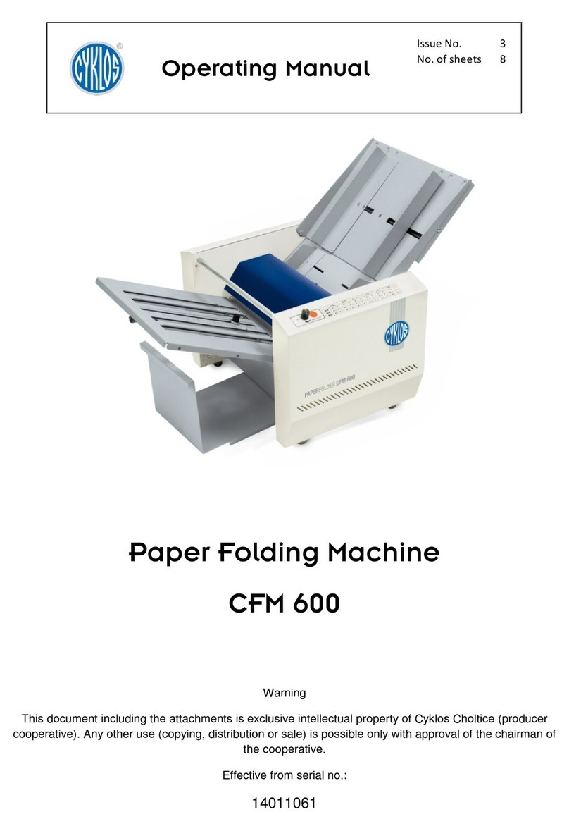
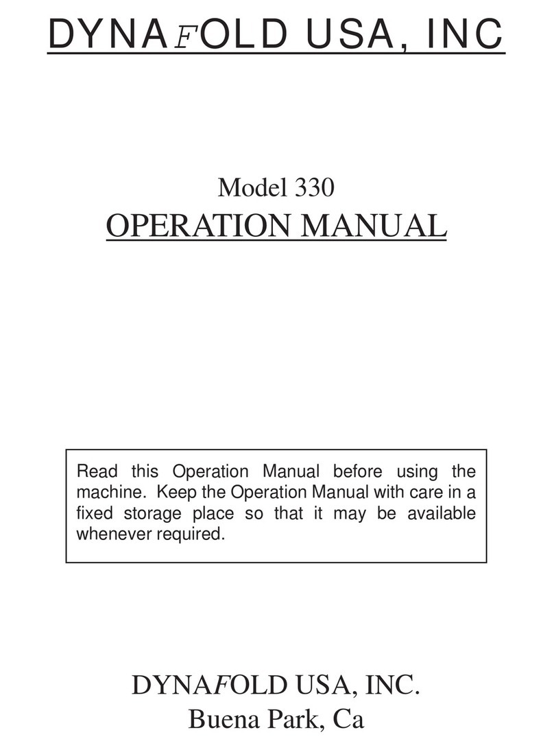
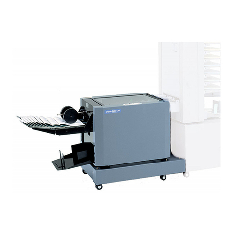
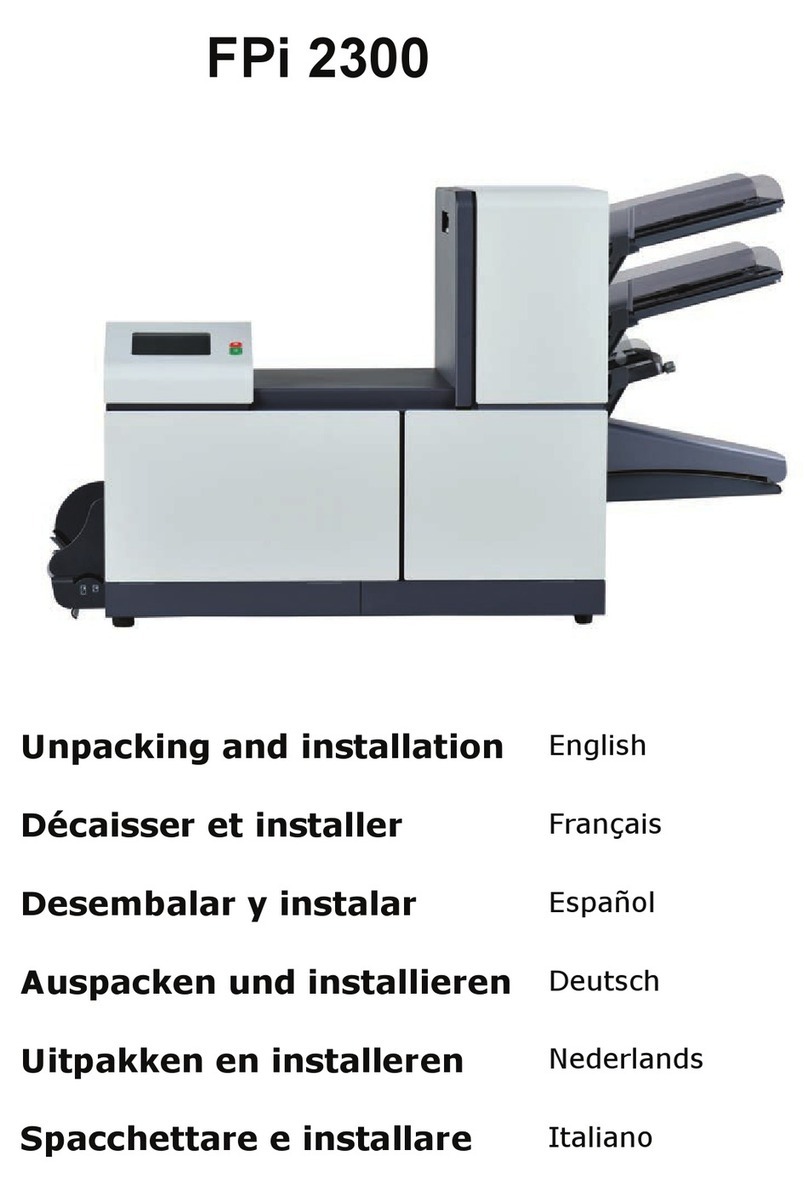
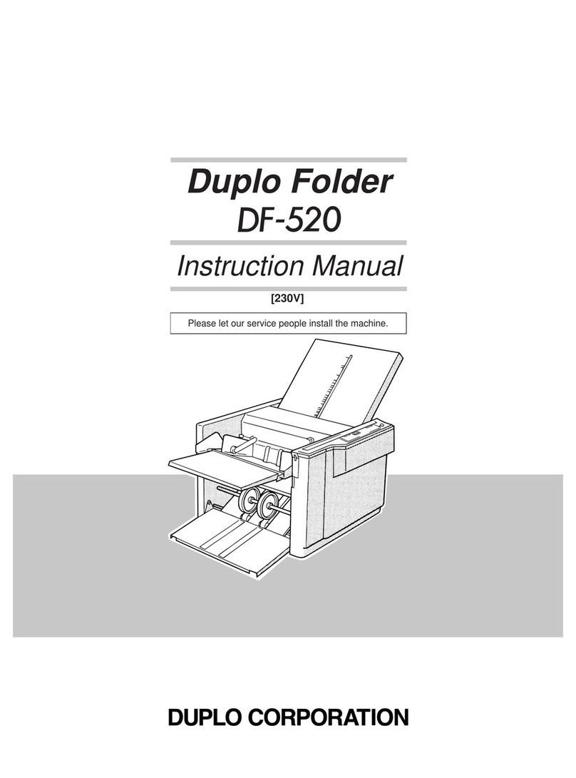
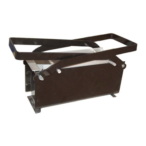
Challenge MEDALIST 820 Technical reference manual

F.669-D
August 2015
MEDALIST 820/870
Instruction and Parts Manual
Serial Numbers:
961533 through 159999,
870-A-150000 and up
Sold and Serviced by
The Challenge Machinery Company
6125 Norton Center Drive
Norton Shores, MI 49441-6081 USA
ChallengeMachinery.com
The Challenge Machinery Company provides owner's manuals on its
products solely as a courtesy to its customers. See the information below
before using this manual.
These manuals are for reference only. These manuals include products which are noncurrent,
unsupported or no longer produced by The Challenge Machinery Company, and are provided solely as
an accommodation to our customers. By providing these manuals, The Challenge Machinery Company
makes no representation or warranty as to the products, their current condition, or their suitabilityor fitness
for use in any particular application, which are the sole and independent responsibility of the product
owner and user.
Older products may not comply with current safety procedures, guidelines or regulations, and it
is the product owner's and user's responsibility to evaluate the suitability and fitness of the
products in their current use and application. The Challenge Machinery Company makes no
representation, warranty or recommendation regarding any modifications which may be required
on non-current or unsupported products. The Challenge Machinery Company assumes no liability
for any modification or alteration to any Challenge product, and any such modification or
alteration to any Challenge product is not authorized by The Challenge Machinery Company. The
availability of these manuals is solely for the purpose of providing reference information for the products.
This manual may not be complete in all aspects of product maintenance and repair. All products should
be used only by qualified and properly trained personnel, following proper safety procedures. All
products should be regularly inspected and maintained, and their condition, application and use should
be periodically evaluated by qualified personnel. Only qualified and properly trained technicians should
perform maintenance, repair and replacement procedures. Attempting these procedures without proper
training may cause machine damage or operator injury!
Products may be unsupported by The Challenge Machinery Company due to age or the unavailability of
parts from their original manufacturer. No parts or product support will be available to repair or maintain
unsupported products. Older products may not be UL listed (if the product does not have a UL label it is
not a listed product), and may not comply with applicable installation or other regulations or requirements
if relocated to a new facility. Many municipalities require a product to be UL listed before an electrician
will connect power to them. Often the cost of updating an older product to comply with current safety
regulations is greater than the value of the product.

F.669-D/820-870/Jan 98
2
INTRODUCTION
WELCOME to the family of Challenge® users. Challenge has been developing and manufacturing Graphics Arts
Equipmentfor over 100 years and is today one of the world’s leading producers and distributors of Paper Cutters,
Paper Drills and Bindery Equipment.
SAFETYALERT! This symbol meansCAUTION OR WARNING: Personal safety instructions! Pay
special attention to the instructions in bold type. Personal injury may result if the precautions are not
read and followed. See SAFETY PRECAUTIONS, page 6.
•This machine is designed forONEPERSONOPERATIONONLY!
•Always DISCONNECT THE POWER before working on this machine.
•DONOT OPERATE WITH ANYGUARDS REMOVED! Replace all guards before operating.
•CRUSH HAZARD - Keephands, hair,cleaning rags,& looseclothing awayfrom rollers.
READ THIS MANUAL BEFORE OPERATING! Follow precautions and instructions given and you should have
years of trouble-free operation. If after reading the manual questions still remain, contact your Authorized Chal-
lengeDealer.
FOR PARTS AND SERVICEcontact the Authorized Challenge Dealer from whom you purchased your machine.
Use the illustrations and parts lists at the back of this manual to identify the correct parts needed. Always give
the SERIAL NUMBER and MODELofyourmachineto insurethatthecorrectparts aresentassoonas possible.
Take a few minutes right now to RECORD YOUR MACHINE SERIAL NUMBER in the space provided on the
front cover of this manual. Also be sure to fill out the warranty card accompanying this manual and return it
DIRECT TO CHALLENGE.
If you bought a used machine, it is important to have the following information on record at Challenge. Copy this
page, fill in the information and send it care of: The Challenge Service Department, 6125 Norton Center Drive,
NortonShores,MI 49441-6081.
CHALLENGE MODEL SERIAL NUMBER
ATTN. COMPANY
ADDRESS
CITY STATE ZIP
PHONE DATE INSTALLED
DEALER’S NAME AND CITY
PLEASE REVIEW THE ENCLOSED WARRANTY SHEET!
It is very important that you read and understand the conditions outlined in the Warranty Information Sheet
includedwiththemanualinformationpackage.
The Warranty Information Sheet must be filled out completely, returned, and beON-FILE at THE CHALLENGE
MACHINERY COMPANY in order for the warranty to be issued for this machine.
WARRANTY INFORMATION
Challenge® is a registered trademark of The Challenge Machinery Company, 6125 Norton Center
Drive, Norton Shores, MI 49441-6081.
Copyright © 1996 by The Challenge Machinery Company. All rights reserved. Printed in the U.S.A.

3
F.669-D/820-870/Jan 98
Medalist Air Feed Table Model Folder
(870 shown with stand)
PACKING LIST
Your folder has been carefully packaged to prevent damage in shipment. Inspect all
shipmentsassoonastheyarereceived. Noteanysigns of damage onthefreightbilland
notify the claims department of the carrierwithin 15 days. All claims for damage or loss
are the responsibility of the receiver,INSPECT PROMPTLY! Checkthecontentsofyour
container(s)* against the following list. NOTE: The vacuum-pump unit is shipped in a
separatecontainer.*
Inthe folder cartonyou shouldfind the followingsub assemblies:
1). Base Machine
2). Feed Table Assembly
3). First Fold Plate
4). Second Fold Plate
5). Stacker Tray Assembly
6). Stacker Wheel Assembly
7). Accessory Package (see parts list of Standard Accessories, pg 66)
8). Vacuum Tubes (3)
9). Sound Guard
10). Feeder Back Stop
11).* CompressorUnit
12).* Strainer,Pump Unit P-102
Thefolderstandwillarriveinaseparatecarton.
(fig. 1)

F.669-D/820-870/Jan 98
4
TABLE OF CONTENTS
INTRODUCTION........................................................................................... 2
PACKING LIST ............................................................................................ 3
SPECIFICATIONS ........................................................................................ 5
SAFETY PRECAUTIONS ............................................................................. 6
CAUTION: POWERLOCKOUTPROCEDURE ............................................. 6
WARNINGLABELDEFINITIONS.................................................................. 7
INSTALLATION ............................................................................................ 8
Cleaning.............................................................................................. 10
Power Hookup ......................................................................................11
Power Controls .....................................................................................11
Control Panel........................................................................................11
Squaring.............................................................................................. 12
OPERATION.............................................................................................. 12
Vacuum Feed Sheet Separator ............................................................ 12
Feeding Paper ..................................................................................... 13
Bleeder Valve (Vacuum Adjustment) ..................................................... 14
FoldPlates.......................................................................................... 14
........................................................................................................... 15
Roller Caliper Set up (870 only) ............................................................ 15
Stacker ............................................................................................... 16
Roller Caliper Quick Set Up Guide........................................................ 16
JamDetector....................................................................................... 16
SPECIALAPPLICATIONS .......................................................................... 18
Scoring ............................................................................................... 18
Perforating........................................................................................... 19
Slitting ................................................................................................ 19
RIGHT ANGLE CROSSFOLD SYSTEM...................................................... 20
Installation........................................................................................... 20
ConveyorSetUp.................................................................................. 22
OPTIONAL CROSSFOLDCONVERSION KIT35537 ................................... 23
MAINTENANCE ......................................................................................... 25
Cleaning.............................................................................................. 25
Rollers ................................................................................................ 25
Vacuum Pump–Compressor................................................................. 25
GeneralInspection............................................................................... 26
Lubrication .......................................................................................... 26
Service ................................................................................................ 26
NOTICE ..................................................................................................... 27
MODEL 820 MAIN ASSEMBLY - Left Hand Side ........................................ 28
MODEL 820 MAIN ASSEMBLY - Right Hand Side ...................................... 30
MODEL 820 MAIN ASSEMBLY - Front View .............................................. 32
MODEL 870 MAIN ASSEMBLY - Left Hand Side ........................................ 34
MODEL 870 MAIN ASSEMBLY - Right Hand Side ...................................... 36
MODEL 870 MAIN ASSEMBLY - Front View .............................................. 38
FOLDPLATEASSEMBLY#1...................................................................... 40
FOLDPLATEASSEMBLY#2...................................................................... 42
FEEDER ASSEMBLY ................................................................................ 44
STACKER ASSEMBLY .............................................................................. 46
LONG STACKER ASSEMBLY .................................................................... 47
STACKER WHEEL ASSEMBLY ................................................................. 48
CALIPERASSEMBLY ............................................................................... 49
MEDALIST STAND ASSEMBLY ................................................................. 50
RIGHT ANGLE STAND ASSEMBLY ........................................................... 51

5
F.669-D/820-870/Jan 98
SPECIFICATIONS
Stock Handling
Maximum Sheet Size 14” x 20” (35.6 cm x 50.8 cm)
Minimum Sheet Size 4” x 6” (10.2 cm x 15.2 cm)
Paper Weight 9# bond to 65# cover
34 g/m2to 176 g/m2
Number of Plates 2
Fold Plate Depth (plate #1) 2” to 17” (5.1 cm to 43.2 cm)
(plate #2) 2” to 9” (5.1 cm to 22.9 cm)
Fold Roller Diameter 1-1/2” (3.8 cm)
Roller Adjustments RollerCalipers
Fold Rollers -820 Rubber
-870 Combination (rubber & steel)
Maximum Speed 30,000 Sheets/Hour (8-1/2” x 11”)(A1)
Dimensions
Overall Height 25” (63.5 cm)
Overall Length 61.5” (156.2 cm)
Overall Width 25” (63.5 cm)
Net Weight (approximate) 275 lbs. (124 kg)
Shipping Weight (approximate) 300 lbs. (135 kg)
Electrical
Standard Motor 120 Volt (± .010%), 60 Hz, 1 Phase, 15 Amps, Service size 20 Amps.
Optional Motor 240 Volt (± .010%), 50 Hz, 1 Phase, 10 Amps, Service Size 15 Amps
Sound Emission
A- Weightedsound pressure level at operator level 6ft. (1.83m);folding 20lb(75g/m2), 8-1/2”x11” (216X279mm)
Machine Folding: 91 dB
A - Weighted sound power level at operator level 6 ft. (1.83m); folding 20lb (75g/m2), 8-1/2” x 11” (216X279mm)
Machine Folding: 101 dB
Challenge reserves the right to make changes to any product or specification without notice and without incurring responsibility to existing units.
JAMDETECTORASSEMBLY .................................................................... 52
ELECTRICAL SEQUENCE OF OPERATION............................................... 53
820 BASIC MACHINE SCHEMATIC - (120 VOLT) ........................................ 54
820 BASIC MACHINE SCHEMATIC - (230 VOLT) ........................................ 55
870 BASIC MACHINE SCHEMATIC - (120 VOLT) ........................................ 56
870 BASIC MACHINE SCHEMATIC - (230 VOLT) ........................................ 57
820/870BACK COVER PLATEASSEMBLY - (120VOLT)........................... 58
820/870BACK COVER PLATEASSEMBLY - (230VOLT)........................... 60
820 CONTROL PANEL ASSEMBLY ........................................................... 62
870 CONTROL PANEL ASSEMBLY ........................................................... 63
120/220VOLT PUMPASSEMBLY ............................................................. 64
STANDARDACCESSORIES...................................................................... 66
CROSS CARRIAGE ASSEMBLY ............................................................... 68
TRANSFER ASSEMBLY ............................................................................ 70
CROSSFOLD ELECTRICAL HOOK-UP ...................................................... 72
CROSSFOLDELECTRICAL HOOK-UPINSTRUCTIONS ............................. 73
IMPOSITION MANUAL ............................................................................... 74
SLITTERSHAFT ASSEMBLYCOMPONENTS ........................................... 76
SLITTERSHAFT ASSEMBLYCOMPONENTS ........................................... 77
ROLLERREPLACEMENTREPAIR KITS ................................................... 78
TABLE OF CONTENTS
(CONT’D)

F.669-D/820-870/Jan 98
6
SAFETY PRECAUTIONS
•This machine is designed and safeguarded for ONE PERSON operation. NEVER operate the ma-
chine with more than one person.
•Safety of this machine is the responsibility of the user and operator. Use good judgement and
common sense when working with and around this machine.
•READ and understand all instructions thoroughly before using the machine. If questions still
remain, call your Authorized Challenge Dealer - Failure to understand operating instructions may
result in personal injury.
•Only trained and authorized persons should operate the machine.
•DO NOT ALTER SAFETY GUARDS OR DEVICES, they are for your protection and should not be
altered or removed.
•DISCONNECT POWER before cleaning, lubricating, servicing, or making adjustments not requir-
ing power. See Power Lockout Procedure below.
•HIGH SPEED ROLLERS - Keep rags, loose clothing and long hair away from rollers. Personal
injury could result from items being caught on rollers.
•Have your electrician make sure the machine is properly grounded.
•Have your electrician check for sufficient power to operate the machine properly.
•OBSERVE ALL CAUTION PLATES AND LABELS on this machine.
•Keep foreign objects off table and away from rollers.
•BE EXTREMELY CAREFUL when handling and changing the slitter, perforating or scoring blades.
Severe lacerations or dismemberment could result from careless handling procedure.
•Keep the floor around the machine free of trim, debris, oil and grease.
•If the machine sounds or operates abnormally, turn it off and consult the Trouble Shooting section
of this manual. If the problem cannot be corrected, have it checked by a qualified service person
or your Authorized Challenge Dealer.
•DO NOT CLEAN ROLLERS WITH THE MACHINE RUNNING! Disconnect the power and use the
handwheel to turn the rollers.
•DO NOT OPERATE WITH ANY GUARDS REMOVED! Replace all guards after adjusting, lubricating
or servicing the machine.
CAUTION: POWER LOCKOUT PROCEDURE
Formaximum safety and toprevent unauthorized
use, turn the power switch to the off position and
disconnect the power cord whenever adjusting,
lubricating, or making repairs to the machine.
This safety symbol means CAUTION/WARNING - PERSONAL SAFETY INSTRUCTION. Read
the instructions because it has to do with safety. Failure to comply with the following instruc-
tions may result in personal injury.
(fig. 2)

7
F.669-D/820-870/Jan 98
SINGLE OPERATOR
SHOCK HAZARD
SHOCK HAZARD
HAZARDOUS AREA
Do not operate with more than one person.
Disconnect power before removing cover. Replace
cover before operation.
Disconnect power before removing cover. Replace
cover before operation.
Disconnect power before cleaning, servicing, or mak-
ingadjustments not requiring power. Do not alter safety
guards or devices, they are for your protection. Re-
place all guards, do not operate with any guards re-
moved.
WARNING LABEL DEFINITIONS

F.669-D/820-870/Jan 98
8
Note: For Right Angle & Crosscarrier assembly see
page20. Openthe standcarton firstand assembleac-
cordingto the instructionsenclosed. Using twopeople,
center the folder on the stand as shown, fig. 3, with the
stand opening towards the front.
INSTALLATION
(fig. 3)
Remove the parts of the folder checking them against
the packing list on page 3 of this manual. (Remove and
savetherollerspacerson820only.)
Steps for assembling the Medalist folder:
the rail guides, (fig. 4), and tighten the eccentric plate
locks,(fig. 6). Notebothplates havetwo setsoflocat-
ing holes in the plate rails. The first set is used when
the plate deflector is down, the other when the plate is
open, see fig. 5.
(fig. 5)
2. Install the #1 (upper) foldplate, fig. 5.
(fig. 6)
3.Make sure thefoldplate pinsare located inthe guide
rails, then lower the plate locks, (fig. 6).
Place the sound cover on top of the #1 foldplate. (the
sound cover is optional on 820 model).
4. Install the feed table. Insert the table between the
(fig. 4)
1. Install the #2 (lower) foldplate. Lower the cover and
insert the #2 foldplate making sure the pins latch into
Do Not Lift
on Drive
Shaft
(round bar)
Notched
Plate Rail
#1 Fold Plate/
Locating Pins

9
F.669-D/820-870/Jan 98
(fig. 7)
sideframes. Install thefeed tableso the notchesin the
side brackets, (fig. 7), mate with the mounting pins in-
side the folder side frames.
NOTE: Mounting pins should be located in the upper
set ofthreaded holes. (Lower holes are used to mount
a crossfold carrier assembly.)
(fig. 8)
5. Install the stacker table assembly, (fig. 8), on the
back of the folder. Insert the spring-loaded end (right
side – viewed from rear of the folder) of the drive shaft
into the locator hole in the side frame, compress the
spring against the side frame and swing the opposite
end into position in the other side frame.
(fig. 9)
6. To pile folded materials, insert ears of stacker tray
into end of stacker table, as shown, fig. 9.
(fig. 10)
7. Attach the stacker wheel assembly to the tie bar
next to the jam detector, as shown, fig. 10.
(fig. 11)
8. Using two people, position the compressor on the
bottom shelf of the stand, (fig. 11).
(fig.12)
9. Install the strainer screen (shipped with the acces-
sory kit) to the intake opening of the blower unit, (fig.
12).
Left Side
Locator
Hole
Locating Pins/
Feeder Notch

F.669-D/820-870/Jan 98
10
(fig. 13)
10. Connect the compressor hoses to the feed table
assembly. The sucker wheel hose threads through the
ty-rap and table support, underneath the feed table,
then onto the end of the sucker wheel shaft tube, as
shown in fig. 13.
Blower
Fittings
Vacuum
Fitting
(fig.14)
11.Attach theairhoses fromthe endsofthe pileguides
to the double hose fittings of the blower. The single
hose from the sucker wheel fitting attaches to the
vacuum fitting, (fig. 14).
NOTE: Make sure all shipping plugs are removed
from the pump openings before attaching the
hoses!
Cleaning
A clean machine will reflect in the quality of the work it
produces. As you unpack your folder, wipe off any
excess protective oil, dirt, or dust which may have ac-
cumulated during shipping.
Keep your machine clean, and wipe off any
accumulationsofpaperdustattheendofeach
day. Cover your machine anytime it is not in
use. See the maintenance section for addi-
tionalcleaninginstructions.
NOTICE
820ONLY: Whenever the machineisnot being
used,reinserttherollerspacersshippedinthe
machinetopreventflatspotsfromforming.This
is a operator controled maintenance function.
Roller flat spots areNOTCOVEREDunderwar-
ranty.
CAUTION:DISCONNECTTHEPOWERBEFORE
INSTALLINGTHEROLLERSPACERS.
1. Close the deflectors on both fold plates.
2. Place one roller spacers at each side of the
feed table and feed between the rollers with
the hand wheel.
3. Removethespacersbeforerunningthenext
job.

11
F.669-D/820-870/Jan 98
Power Hookup
The standard Medalist Folder requires a 120 volt, 20
amp circuit with a three-prong, grounded receptacle.
It is the customer's responsibility to provide a power
line that meets all local electrical codes.
Optional 50 Hz, 240 volt machine draws 10 amps.
Provide proper circuit to handle load.
WARNING: DISCONNECT PROCEDURE:
NEVER PULL THE CORD to disconnect
the plug. Cord fatigue could lead to shorts
resulting in fire or personal injury from shock.
Always grasp plug body to disconnect power
cord, fig. 2, pg. 6.
WARNING: SHOCK HAZARD! NEVER
CUT THE GROUND LUG from a three-
prong plug to fit a two-prong socket. Possible
shock could cause personal injury or death.
Hire a qualified electrician to provide a power
source that meets electrical requirements and
all local electrical codes.
Power Controls
Compressor
PowerCord
PowerCord
Socket
Power
Switch
(fig. 15)
The power panel, (fig. 15), is located on the back of
the folder below the first fold plate and stacker table.
The compressor unit power cord plugs into the socket
on the left side of the power panel.
Makesure thepowerswitch isin theOFF("O" orOpen)
position. Theexternal power cord plugs into the power
panel socket next to the switch.
Control Panel
Counter
Reset
Sheet
Counter
Speed
Control Roller
Motor Compressor
Motor
(fig.16)
The individual on/off switches for the compressor and
therollermotorarelocatedon top oftherollguardcover,
(fig. 16, 870 model shown). They are marked with the
international ON (I) and OFF (O) symbols.
The rotary knob is the rollerSpeed Control.
The Sheet Counter window and the Counter Reset
button (optional on 820 models) are located on the far
leftof thiscontrol panel (as viewed fromthe feedtable).

F.669-D/820-870/Jan 98
12
Front Guide
Adjusting
Knob
OPERATION
Squaring
Inorder foryourmachine tofold stock squarely,itmust
be fed into the rollers square. Your Medalist has been
adjusted at the factory and should only require peri-
odic checks. The Medalist has a unique feed table ad-
justmentfeature toquickly andeasily adjustit ifneeded.
WARNING: DISCONNECT THE POWER.
See power lockout procedure on page 6.
Table
Center
Mark
Scale
Center
Line
FeedTable
Squaring
Screw
(fig. 17)
1. Adjust the feed table squaring screw and align the
center line of the scale with the center mark on the
feeder table, (fig. 17).
Side
Guides
Scale
(fig. 18)
2. Loosely position the feed table side guides to the
scaleson thefeed table,(fig. 17& 18). Readthe front
scale at the inside edge of the side guide clamp block.
The rear scale will line up with the inside edge of the
side guide. The scales are set up to center the paper
on the sucker wheel. Initially set each side guide 1/4"
(6mm) wide. Do not tighten the lock knobs.
Vacuum Feed Sheet Separator
The sheet separator will have to be adjusted for the
weight of stock you are folding. Ideal adjustment will
feedonlyonesheetwithout marking thepaperorfeed-
ingdoubles. Use the following procedure to get started.
Fine tune these adjustments according to the condi-
tion of the paper and the environmental conditions of
your particular work area.
Adjustment procedure:
1. Raise the separator (ccw) to avoid marking the
sucker wheel.
NOTE: DO NOT MAKE SEPARATOR
ADJUSTMENTS WHILE THE FOLDER IS
RUNNING.
3. Raise the sheet separator (ccw) so it is away from
the sucker wheel (fig. 19). Place a sheet of the paper
to be folded on the feed table. Slide the sheet forward
into the rollers. The sheet must contact the rollers
evenly and not touch the side guides. Turn the hand
wheel so about 1/2" (3mm) is pulled into the rollers.
4.Position the operatorside guideso it isjust touching
the sheet but not pushing it. The side guide must be
even to the sheet from end to end. Tighten the front
lock knobs then the rear knobs, (fig. 17 & 18).
5. Repeat step 4 on the nonoperator side guide.
6. The paper will now feed square into the rollers. Now
that the side guides are square, the feed table squar-
ing screw, (fig. 17), can be adjusted for fine tuning the
overall squareness.
SeparatorGuide
AdjustingKnob
SeparatorGuide
Plate
2. Turn the handwheel until the separator tip is posi-
tionedover a solidportion ofthe sucker wheel,i.e. be-
tween the rows of holes.
(fig. 19)
Front Guide
Adjusting
Knob

13
F.669-D/820-870/Jan 98
3. Place a one inch wide (25mm), double thickness
piece of stock to be folded under the tip of the separa-
tor plate, (fig. 19). Lower the separator (cw) until there
is a slight drag on the paper as it is pulled from under
theseparator.
(ill. 1)
Vacuum
Advance Backstop
(fig. 20)
4. The vacuum advance knob is located on the side of
the feed table, (fig. 20). Adjusting the knob will position
where the vacuum contacts the lift of paper, ill. 2a &
2b. Raising the knob will move the vacuum away from
the lift and toward the rollers (light papers). Lowering
the knob will move the vacuum contact toward the lift
and away from the rollers (heavy papers).
Horizontal Separator Adjustment
1.Raisetheseparator(ccw)toavoidmarkingthesucker
wheel.
2. Loosen knob (ill. 2). Setscrew in Accessory Kit,
(item #14, pg 67), may replace knob if desired.
3. As a starting reference, turn the handwheel until a
set of sucker wheel holes is at the 12 o’clock position.
4.Adjust separator assembly so that the plate is 1/16”
forward of the 12 o’clock position, measure from the
feed side of the plate.
5. Tighten knob (ill. 2).
(2a)
(2b)
(ill. 2)
Feeding Paper
1.Load a liftof paper onto the feedtable. The liftshould
be no higher than the side guides, 2" (51mm). Position
the backstop up against the lift, (fig. 20).
2. Turn on the air/vacuum pump. The air should float
the bottom of the lift approximately 1/16 to 1/8" (16 to
32mm). Air blast can be controlled by adjusting the
valve located at the end of each side guide, (fig. 21 &
fig. 22, pg 14).
Air Blast
Openings Air Blast
Control
Knobs
(fig. 21)
Knob
Knob

F.669-D/820-870/Jan 98
14
AirBlast
Openings
Separator
Guide Lock
Set Screw
3. Turn the speed control to 1/2 or full speed. Place
your thumb on the back of the lift to keep paper from
feeding. Press the green rocker switch, the sucker
wheel will start to turn. Reduce the pressure of your
thumb to feed only 3 to 4 sheets. Press your thumb
down to stop the feeding again. Press the red rocker
switchtostopthesucker wheel fromturning.Ifthepaper
didnotfeed,adjustthe position ofthevacuumadvance
(fig. 20, pg 13), bleeder valve (fig. 23), or sheet sepa-
rator, (fig. 19, pg 12).
4. Check the accuracy of the 3 or 4 sheets fed. It may
be necessary to adjust the fold stop, (fig. 24), or the
squareness of the fold stop, (fig. 25, pg 15), or the
squareness of the side guides. Try only one adjust-
ment at a time then repeat step 3.
5. If the folds look good, the job may now be run. The
speed of the folder will affect the accuracy of the folds.
Foldssetupatslowspeedwillbedifferentathighspeed
and will need to be fine tuned.
Note: All of the controls mentioned above contribute to
smooth and accurate folding. There are many combi-
nationspossible depending on the conditionof thepa-
per and environment.
(fig. 22)
Bleeder Valve
(fig.23)
FoldPlates
Plate set up will depend on the type of stock and type
of fold you require. The fold plate design on the Med-
alist allows changing from open or closed deflector
(up and/or down folds) without removing or turning
the plates.
(ill. 3)
A good understanding of the roller/plate configuration
will help you decide which plate to open or close for up
or down folds. Illustration 3 shows the paper path for a
common Z-fold.
A self adhesive folding guide label is included with the
manual and may be conveniently placed on the deliv-
ery tray. Used along with scales on the fold plates, the
guide will help you quickly establish a rough set up for
some of the most common folding jobs.
Inch/mm
Scale
QuickSetup
Scales(read at
thesepoints)
PlateStop
Coarse adjustments are made by loosening the lock
screws on the plate stops, (fig. 24), then moving the
stop. Theplatestoplinesupwith the scalemarksalong
its front edge (not where the paper contacts the stop).
Fineadjustments are madewith themicroadjust knobs
on the ends of the fold plates, (fig. 25, pg 15).
(fig. 24)
There is a bleeder valve on the vacuum pump, (fig.
23), which allows for vacuum adjustment from com-
pletely off to completely on. General settings for the
bleeder valve are half open for 20# stock, and closed
for 80# and heavier stock. If your machine is feeding
doubles, this can be opened slightly to “relieve” some
of the vacuum and stop the double feeding.
Bleeder Valve (Vacuum Adjustment)

15
F.669-D/820-870/Jan 98
Micro-adjust
Knobs
(fig. 25)
Holding
Pin
(fig. 26)
Foreasyaccess tothesecond (bottom)foldplate while
making coarse adjustments (NOT WHILE RUNNING)
the feed table may be lifted out of the way and held
there by inserting the holding pin in the side frame,
(fig. 26).
Roller Caliper Set up (870 only)
WARNING: DO NOT MAKE ROLLER
ADJUSTMENTS WITH THE FOLDER
RUNNING! Serious personal injury or
machine damage could result from tools,
fingers, hair or clothing being caught by rollers.
Always disconnect the power cord when
setting rollers. Never operate folder with any
guards or fold plates removed.
Adjustable calipers are used on the Medalist 870 to
obtain clean crisp folds on a variety of stock. The
proper amount of paper strips (of the same material
being folded) in each caliper will give the best grip for
agood fold. Asthe paperis folded, thethicknesses of
thepaper passing betweenthe rollers increases.The
number of paper strips placed in the calipers should
be equal to the minimumthicknessofthepaperpass-
ing between the rollers (tail end of the sheet).
Roller
Calipers
(fig. 27)
To provide the proper clearance between rollers, 3/4"
wide paper strips are inserted into the calipers, (fig.
27). Simply press the caliper lever and insert the cor-
rect number of strips into the open gap. Put the same
number of strips into both sides of the folder. Do not
use folded or torn strips of paper (they may give false
readings). Illustration 4 diagrams the position of roll-
ers, fold plates, feed table, calipers and the correct
number of paper strips to be placed into the calipers
for a common "Z" fold.
The chart on page 16 shows the caliper and plate set
up for several common folds.
(ill. 4)
N O T I C E
Whenever the machine is not being used, put
chipboard into the roller calipers in place of
paper to prevent rollers from getting flat spots.
This is an operator controlled maintenance
function. Roller flat spots are NOT COVERED
under warranty.

F.669-D/820-870/Jan 98
16
Roller Caliper Quick Set Up Guide
Roller calipers on the Medallist 870 feature quick set
up calipers. Calipers adjust the space or tension be-
tween rollers to provide the proper grip on the paper
forclean crispfolds. Each time the paperis folded,the
thickness increases. To compensate for this, the cali-
pers on bothsides of the machine have strips of paper
inserted. The correct number of paper strips to be
placed into the calipers corresponds to the tail end of
Fold Type #1 Caliper #2 Caliper #3 Caliper #1 Plate #2 Plate
Letter 1 1 3 open open
"Z" 1 1 3 open open
Half 1 2 2 open closed
Double 1 2 4 open open
Parallel
Stacker
The stacker consists of a table, belts, wheels, stacker
springs, and a delivery tray. The stacker accumulates
Stacker
Springs
Stacker
Wheels (fig. 28)
foldedstock foreasy removaland stocking. Thesprings
and stacker wheels keep the delivered sheets from
opening up, interleaving and creating paper jams.
Set up:
1.Setthestackerwheelsbackfromtheslittershaftthe
width of the folded sheet plus an additional 1/4".
2. The wheels should be placed towards the center
of the folded piece to stop it in position as it is ejected
from the slitter assembly.
3. Center stacker belts under stacker wheels.
the sheet which will be the minimum thickness of the
stock passing between the rollers. Use 3/4" wide, cut
stripsof the same material being folded. (Torn or folded
strips will give improper settings.) Make sure that the
calipers on both sides of the machine are set up with
exactly the same number of paper strips. The chart
below gives the set ups for calipers and plates for sev-
eral common folds.
4. Position the stacker springs on the slitter shaft tie
bar. They should be positioned towards the outside of
the sheet to hold the edges of the folded piece down,
(fig. 28). The springs may be bent for best operation.
5. Depending on the stock and the type of fold, best
stacking performance may be had by using just the
springs or the stacker wheels only. Fine tune these
adjustments as you run your job.
6. Loosen lower knob to adjust stacker wheels from
side to side.
Jam Detector
As standard equipment, all Medalist folders come
equipped with a delivery area jam detector, (fig. 29).
Thisdevice senses jams at the feed table and immedi-
ately stops the folder until the jam is removed and the
machine is restarted. The jam detector is mounted on
the center of the tie bar and looks similar to a third
stacker spring, it may be bent for best operation.
Jam Detector
(fig. 29)
Lower
Knob

17
F.669-D/820-870/Jan 98
NOTES NOTES

F.669-D/820-870/Jan 98
18
Scoring
Your Medalist includes perforator and scoring blades,
two scoring collars, a rubber score wheel, a blade
holder and a grooved perf collar as standard equip-
ment, (fig. 30).
Installation of accessory blades and collars is simpli-
fiedbytheremovable slitter assembly,(fig.31).Loosen
the set screw in the sliding collar, (fig. 31). Simply
slidethe slitter shaftto theright, bring theopposite end
out of the folder frame and remove the shaft assem-
SPECIAL APPLICATIONS
CAUTION: Use extreme care when handling and changing the
scoring or perforating blades. Severe lacerations could result
fromcarelesshandlingprocedures.
Scoring
Position your scoring blade as desired. Scores should
bemade sothat theblade runson theside ofthe sheet
that will be on the inside of the finished fold. Scores
may be made on the Medalist in two ways;
1. The blade may be run on top of the
rubber scoring wheel supplied. The
rubber wheel is simply positioned on
the slitter shaft opposite the score
blade.
2. For a more controlled fold as might
be needed with various stock thick-
nesses, use the scoring collars on the
shaft opposite the score blade, (ill. 5).
Positionthecollarson eithersideofthe
SLITTER ACCESSORIES
(ill. 5)
(fig. 30) (fig. 31)
Score Blade
Score Collars
Perf
Stripper
Stacker
Springs
Perf
Collar
Rubber
Wrenches
Perf
Blade Score
Blade Blade
Holder Score
Collars
Score
Wheel
Slitter
Shaft
Set
Screws
Sliding
Collars
Slitter
Shaft
bly. Install the accessory items as required and rein-
stall.
NOTE: Before tightening blade holder screws, mount
the holder with the blade loosely attached onto the slit-
ter shaft. Now tighten the holder screws. This en-
suresthe blade is concentric with the slitter shaft mak-
ing for easier installation and even scores and perfs.
scoring blade. The degree of score desired may be
obtained by moving the collars either closer or farther
away from the blade.

19
F.669-D/820-870/Jan 98
Perforating
Perforating may be used to deliver a perforated sheet flat or as a guide for
additional right angle folds.
The perforating blade (and any additional blades purchased in addition to the
one supplied) is mounted on the upper shaft of the slitter assembly. The perfo-
rating blade is run against the inside edge of the groove in the perforating collar
mounted on the lower shaft, (ill. 6a).
The curved slotted stripper finger is mounted on the square tie bar above the
slitter assembly with one finger on either side of the perf blade. The stripper
finger prevents the paper from wrapping around the perf wheel. It may be ad-
justed by loosening the button head screw in the mounting bracket and moving
the fingers up or down, (ill. 6a). The fingers should be adjusted as close to the
blade as possible without rubbing on it. Contact with the holder will cause pre-
mature wear of the stripper fingers.
Scoring
Slitting
Withthe addition ofa pairof slitting blades,folded sheetsmay be cutapart after
folding or before delivery to a right angle cross carrier. Slitting blades are
(ill. 6b)
Perforating (ill. 6a)
*NOTE:Astripper is requiredfor each perforatorblade.
Stripper*
Adjusting
Screw
PerforatorBlade
Perforator Collar
attachedinthesamemanneras perforating blades. Notethatbladesaremounted
to blade holders with special flathead countersunk screws. Mount the blade/
holderunit onto the upper shaftin theposition theslit is to be made.Position the
secondblade/holder ontothe lowerslitter shaftas shownin illustration6b above
so that the flat edges of the blades fit together snug (too much space will give
ragged cuts). Slitting blades may also be installed to run against a collar as
shown in the perforating instructions.
Slitting Blades

F.669-D/820-870/Jan 98
20
RIGHT ANGLE CROSSFOLD SYSTEM
(fig. 33)
(fig. 34)
(fig. 32)
A little downward pressure on the crosscarrier assem-
blywill helpto align the holes toaid installingthe mount-
ing screw (the friction drive is located under the right
siderequiring the pressure to alignthe mountingholes).
CAUTION: Disconnect the power to all
unitsbeforepositioningthecrossfoldsys-
tem and making the electronic connections.
Installation
1. Remove the stacker wheel assembly and delivery
tablefrom your folder. See noteon page70.
2.Reposition the folderon itsstand. Move thefolder to
thebackedgeofthestandasshowninthephotoabove,
fig. 32.
3. Place the folder for the crosscarrier onto its stand. It
shouldalso bepositioned towardsthe backedge ofits
stand as shown in fig. 32.
4. Install the cross carriage support legs to the cross
carriage frame, (fig. 33). The legs are mounted with
two, #10-24 x 3/8" button head cap screws.
5. Insert the crosscarrier assembly between the side
framesmakingsure thesupportlegs restonthe cross-
carrier stand. Make sure the mounting pins for the
crosscarrier conveyor assembly are in the lower set of
holes in the roller side frames, (fig. 34). Install the left
hand screw first, then the right hand side.
Button Head
MountingScrews
Support
Leg
Leveling
Screw
Button Head
MountingScrews
Support
Leg
Leveling
Screw
Use LOWER hole
forCrosscarrier
Mounting Pin
Challengeoffers a RightAngle Crossfold Systemwhich
is used in conjunction with the Medalist
TheSystem consistsof asecond parallelunit, across-
fold carrier table, shorter stand and a transfer assem-
blywhich displaces the delivery table of the folder (the
deliverytableis placedonthe backofthe crossfolder).
This manual suits for next models
1
Table of contents