Chapman Machinery FM Series User manual


Page 2
Contents
HSE Information................................................................................................................................3
Important Safety Information ..........................................................................................................4
DEFINITIONS..................................................................................................................................4
Safety Information........................................................................................................................4
Transportation Safety ...................................................................................................................5
Operating Safety ...........................................................................................................................5
Description....................................................................................................................................5
Noise Levels ..................................................................................................................................5
Technical Information.......................................................................................................................6
Component Identification.............................................................................................................6
Identification.................................................................................................................................6
Implement Decals.............................................................................................................................7
Attachment.......................................................................................................................................8
Before Attaching the Machine......................................................................................................8
Attaching the Machine..................................................................................................................8
Operation..........................................................................................................................................8
Operating Limits............................................................................................................................9
Daily Checks ..................................................................................................................................9
Storage..........................................................................................................................................9
Offsetting ......................................................................................................................................9
Starting Work..............................................................................................................................10
Forward Speed............................................................................................................................10
Drive Belts & Power Transmission..................................................................................................11
Belt Replacement........................................................................................................................11
Maintenance...................................................................................................................................12
Maintenance Schedule ...............................................................................................................12
Tyre Pressures.............................................................................................................................12
Maintenance Instructions...........................................................................................................13
Grease Points ..........................................................................................................................13
Flail Condition & Replacement ...................................................................................................14
Troubleshooting..........................................................................................................................14
Machine Disposal........................................................................................................................14
Warranty.........................................................................................................................................15
CE Declaration of Conformity.........................................................................................................15
THIS MANUAL MUST BE HANDED TO THE OPERATOR BEFORE USE. THE OPERATOR MUST UNDERSTAND
FULLY THE CONTENT OF THIS HANDBOOK BEFORE USING THE MACHINE FOR THE FIRST TIME. OF THE
IMPLEMENT IS RESOLD, THIS MANUAL MUST ACCOMPANY THE MACHINE.
NOTE:
The information contained in this manual is correct at the time of going to press. However, in the course
of development, changes in specification are inevitable. Should you find the information given differs
from your machine, please contact Chapman Machinery Ltd direct for advice. Use only Chapman
Genuine Service Parts on Chapman Machinery and Machines.

Page 3
HSE Information
Safe use of all-terrain vehicles (ATVs) in agriculture and forestry –AIS Sheet 33
Introduction
This information sheet gives advice on the safe use of ATVs. It covers
the two main types used in off-road working in agriculture and
forestry, which are:
•sit-astride ATV / sit-in machines
•side-by-side mini-utility vehicles,
The Full HSE information sheet can be found here or using the QR
Code at the bottom of the article:
https://www.hse.gov.uk/pubns/ais33.pdf and must be read prior to
any ATV/UTV use. Below are related extracts to trailed machinery.
REMEMBER - GET PROPERLY TRAINED AND ALWAYS WEAR
HEAD PROTECTION
Training
Under the Provision and Use of Work Equipment Regulations 1998
(PUWER), there is a legal requirement for employers to provide
adequate training, and to ensure that only employees who have
received appropriate training in their safe use, including the use of
any towed equipment or attachments, are permitted to ride ATVs.
The same requirements apply to the self- employed. HSE regards
training provided by recognised training providers as being
adequate for the purposes of PUWER.
Protective clothing
More than half of all ATV riders have been thrown off at some time.
As these machines are not fitted with either a cab or roll bar, your
only protection is what you wear.
●
Head protection is vital. The majority of ATV fatalities in the
UK in the last ten years have been caused by head injuries.
Nobody who died from head injuries was wearing a helmet.
Helmets would certainly have prevented most, if not all, the
deaths. Youshould always wear a helmet when riding an
ATV. All helmets should have a chinstrap and be capable of
being used with suitable eye protection. The type of helmet
chosen should be based on an assessment of the
circumstances in which the ATV will be used, eg the types of
surface travelled over and anticipated speeds. The harder the
surface and higher the speed the greater the degree of
protection needed. NB: Forestry helmets and industrial hard
hats are not acceptable for any ATVoperations.
●
Wear clothing that is strong and covers your arms and legs.
Gloves are useful for protection and to keep hands warm in
cold weather for good control of the ATV.Wear sturdy, ankle-
covering footwear, eg boots or wellingtons that are strong,
supportive and have good wet grip.
●
Protect your eyes from insects and branches with either a
visor or goggles.
Trailed equipment and loads
Ensure all riders know the manufacturers recommended towing
capacity and drawbar loading limit. Always operate within these
requirements.
Remember that your ability to control the ATV by your body
movements will be considerably reduced when carrying a load or
towing a trailer.
●
When selecting trailed equipment look for:
-
over-run brakes;
-
a swivel hitch drawbar;
-
bead lock rims on wheels;
-
a low centre of gravity and a wide wheel track;
-
a long drawbar; and
-
attachment points for securing a load.
●
Check the weight ratio between your ATV and its trailed load.
This needs to be assessed for each operation. As a general
guide, on level ground, braked trailed equipment can be a
maximum of four times the unladen weight of the ATV. For
unbraked trailed equipment the maximum should be twice
the unladen weight. These loads should be reduced when
working on slopes, uneven ground or poor surface conditions.
Follow the manufacturers advice for your particular machine.
●
Weight transfer is also important. Stability and resistance to
jack-knifing is improved if some load is transferred onto the
ATVʼs drawbar. Approximately 10% of the gross weight of the
loaded trailer is recommended, but this should not exceed the
manufacturers drawbar loading limit. Remember that weight
transfer can change dramatically when you start going up or
down hill.
●
When selecting mounted equipment, make sure it is within the
manufacturers approved weight limit, with a low centre of
gravity, and controls which are easy to operate but do not
create a hazard. Where equipment is added to one end of the
machine, add ballast at the other end to maintain stability.
●
Loads carried on racks must be well secured, e.g. with ratchet
straps, and be evenly balanced between the front and rear,
except where they are deliberately altered to aid stability
when going up or down a slope.
●
Only tow a load from the hitch point. Loads towed from other
points such as the rear rack have caused sudden rear
overturning even on slight slopes or with slight acceleration.
Ropes or chains should not be used to drag a load where they
can become caught on a wheel. This may lead to
entanglement with the brake cable, causing unexpected
braking.
Further information
For information about health and safety go to
https://www.hse.gov.uk/
© Crown copyright This publication
may be freely reproduced, except for
advertising, endorsement or
commercial purposes. First published
05/99. Please acknowledge the source
as HSE.

Page 4
Important Safety Information
Always read this manual before fitting or operating the machine –whenever any doubt exists contact your
dealer or the Chapman Machinery Service Department for advice and assistance.
DEFINITIONS
The following definitions apply throughout this manual:
WARNING - An operating procedure, technique etc., which can result in personal injury or loss of life if
not observed carefully.
CAUTION - An operating procedure, technique etc., which can result in damage to either machine or
equipment if not observed carefully.
NOTE - An operating procedure, technique etc, which is considered essential to emphasis.
LEFT & RIGHT HAND - This term is applicable to the machine when attached to the towing vehicle and is
viewed from the rear –this also applies to tractor references.
Safety Information
•Do not operate this equipment unless you have studied this manual in full
•Only use this machine for its designated task - improper use is both highly dangerous and damaging to
machine components
•Both operators & maintenance fitters should be familiar with the machine and fully aware of dangers
surrounding improper use or incorrect repairs
•Before starting, carry out a visual check on both machine & towing vehicle as regards functionality,road
safety & accident prevention rules
•Even when using the machine correctly, foreign objects such as stones may be thrown a considerable
distance. It is imperative that nobody stand within the danger area. If working near roads, buildings children
or animals provision must be made for containment of ejected material and sufficient warning signs / notices
placed around the working area
•The condition of flails and of machine guards must be checked before beginning the day’s work. Worn or
damaged flails must be replaced before you use the machine. Flails must be replaced in pairs to ensure rotor
balance is maintained.
•During checks or repairs, ensure the machine cannot be started by other persons bymistake
•Never wear loose clothing which could get caught in rotating equipment
•Never carry passengers on the towing vehicle
•Never approach the machine until the rotor has stopped rotating
•Do not stand near the machine when operating
•Damaged or missing safety decals must be replaced immediately
•Before leaving the machine unattended, remove the starting key (if applicable)
•ENSURE emergency stop switch is SECURELY attached to the towing vehicle and within reach of the operator
at all times

Page 5
Transportation Safety
•When transporting, especially over rough ground, reduce speed to prevent damage to machine.
•Ensure ignition keys are removed
•This machine is not road legal. DO NOT tow on publichighways
•Never transport the machine with the rotor running, even for small distances.
Operating Safety
•If wires, ropes or chains should become entangled in the rotor stop immediately to prevent damage or dangerous
situations; stop the rotor and the towing machine, take out the starting key or safety cut-out. Put working gloves
on; clear the rotor with the aid of pliers or shears. Do not try todisentangle.
•Pay special attention when working with the machine not to touch fixed objects such as road-drain, walls, shafts,
kerbs, guard rails, tracks etc. This could cause breakage of the flails, which could be thrown out of the machine at
very high speed.
•Do not use the machine when excessive vibration is experienced, as this may cause breakage and serious damage
- find the cause of the vibration and eliminate it before using the machine again.
Description
The FM Series of flail mowers are designed as self-powered units to be towed behind a suitable, ATV,UTV,4X4,
compact tractor or lawn tractor towing vehicles. Designed for vegetation management of paddocks, fields and
parkland, the FM series can handle material up to small saplings and brush.
The FM120 has a 1.2m cut and comes with a Honda GX630 21hp V-Twin electric start petrol engine.
The FM120PRO has a 1.2m cut and comes with a Honda GX700 23hp V-Twin, FSI, electric start petrol engine.
The FM150 has a 1.5m cut and comes with a Honda GX630 21hp V-Twin electric start petrol engine.
The FM150PRO has a 1.5m cut and comes with a Honda GX700 23hp V-Twin, FSI, electric start petrol engine.
These machines should however only be used to perform tasks for which they were designed - use of the machine
for any other function may be both dangerous to persons, and potentially damaging to components. Use of the
machine beyond the stated usage may invalidate any applicable warranty, as well as being poten- tial in breach of
applicable safety regulations.
Noise Levels
The sound of this machine, as measured at the typical operator location under normal operating conditions, is 91db. If being
towed by an open-cab vehicle, it is essential that ear defenders or a suitable helmet is worn at all times. If being towed behind
an closed-cab UTV, 4x4 or similar, then the cab should remain closed to reduce noise.
Ear defenders or other suitable protection should be worn at all times when operating

Page 6
Technical Information
Component Identification
EMERGENCY STOP CONTROL MUST BE WITHIN REACH OF THE OPERATOR DURING NORMAL USE
ENSURE CONTROL EQUIPMENT IS SECURELY ATTACHED TO THE TOWING VEHICLE BEFORE USE
CHECK OPERATION OF EMERGENCY STOP CONTROL BEFORE COMMENCING WORK

Page 7
Identification
Each machine is fitted with a serial plate (shown below) which details the following:
1. Model
2. Date of Manufacture (DOM)
3. Serial Number
4. Mass
When enquiring regarding spares or additional
equipment, ensure you have this information to hand.
Implement Decals
If your implement does not contain all of the decals shown below, please contact your equipment supplier for
replacement decals before use.
Note: All decals must be present and visible. It is imperative that these are replaced if damaged to prevent
potential harm to users.
Carefully read operators
manual before handling
this machine. Observe in
structions and safety rules
when operating
Caution - Entanglement
Hazard. Keep hands away
from rotating
components
Caution - Rotating blades.
Maintain sensible working
distance from machine
and keep hands and feet
clear of blades
Caution - risk of flying
objects. Keep a safe
distance from machine at
all times

Page 8
Attachment
Before Attaching the Machine
Before attachment, ALWAYS ensure the following:
•All safety guards & decals are in good working order and correctly fitted
•All blades are correctly fitted, undamaged, and not worn to excess
•Lubrication points have been lubricated as per scheduled maintenance period
•The engine oil level is correct & has been maintained as per the handbook
•Drive belt(s) are in good working order
•The tyres are free of damage and inflated to the correct pressure
Attaching the Machine
NOTE: This machine is designed to attach to the towing vehicle through a 50mm diameter ball hitch
or pin hitch.
1. Reverse the towing vehicle up to the machine.
2. Attach the machine onto the towing vehicle’s coupling using either the auto-lock coupling or
suitable pin
hitch. Ensure the hitch is securely attached to the towing vehicle
3. Attach the emergency stop control box to the towing vehicle, in a secure location within easy
reach by the operator.
4. With the engine OFF, adjust the working height to a suitable level by turning the height adjuster
on top of the machine.
5. Level the machine to suit the drawbar & cutting height. This is achieved by twisting the link
connector fitted to the drawbar. When on level ground, the top face of the mower deck (where the
engine is mounted) should be approximately parallel to the ground.
Operation
NOTE: Ensure that the operator is suitably qualified to use a machine of this nature and that they
have fully read and understood this manual - they should be aware of all safety aspects relating to
the safe use of the machine.
Prior to starting work the area to be cut should be checked for dangerous objects such as
large stones, wood, wire, glass etc. –hazardous objects should be removed from the area
prior to operation with the machine. The location of unmovable or natural hazards such as
drain covers should be noted, or if necessary ‘marked’, to indicate to the operator that the
area should either be avoided or additional caution adopted whilst working around the
hazard.

Page 9
Operating Limits
Minimum / Maximum Ambient Temperature: -15°C /40°C
Minimum / Maximum Altitude: 0 meters / 1500 meters *
Maximum Inclination: 20° in any direction
*Adjustment to carburetor jet size above 1500m will allow operation above this level, please call
for advice.
Daily Checks
Before use each day, and with the engine switched off and keys removed, the following checks
should be undertaken;
•Flails - With the engine switched off and keys removed, the condition of the flails should be
checked. Any damaged or missing flails should be replacedimmediately.
•Engine - Fluid levels should be checked daily before use and topped-up as necessary. Ensure
the air intake and screen grid are clear of debris. Ensure engine is in good order and
maintained as per engine manufacturer schedule.
•Bearings - Ensure bearings are in good order and greased as per the maintenance schedule.
•Belts - Ensure belts are in good order, free of debris, dirt and grease and do not have signs of
damageeg. cracking, frayed edges, uneven wear.
•Fuel - Ensure fuel is clean and free of dirt / debris. If necessary, check condition of fuel filter.
•Hitch - Check condition of swivel hitch and ensure this is attached securely to towingvehicle.
•Tyres - Ensure tyres are free from damage and inflated to the correct working pressure for the
conditions at hand
Storage
For extended periods of storage, it is advisable that the machine be first cleaned thoroughly and
fully lubricated. Any servicing and maintenance should be undertaken prior to storage, and any
worn components replaced.
NOTE: Fuel should be treated with a suitable fuel stabilizer before extended storage!
DO NOT OPERATE BEYOND OPERATING LIMITS, DAMAGE TO MACHINERY OR INJURY TO
OPERATOR MAY OCCUR.
Page 10
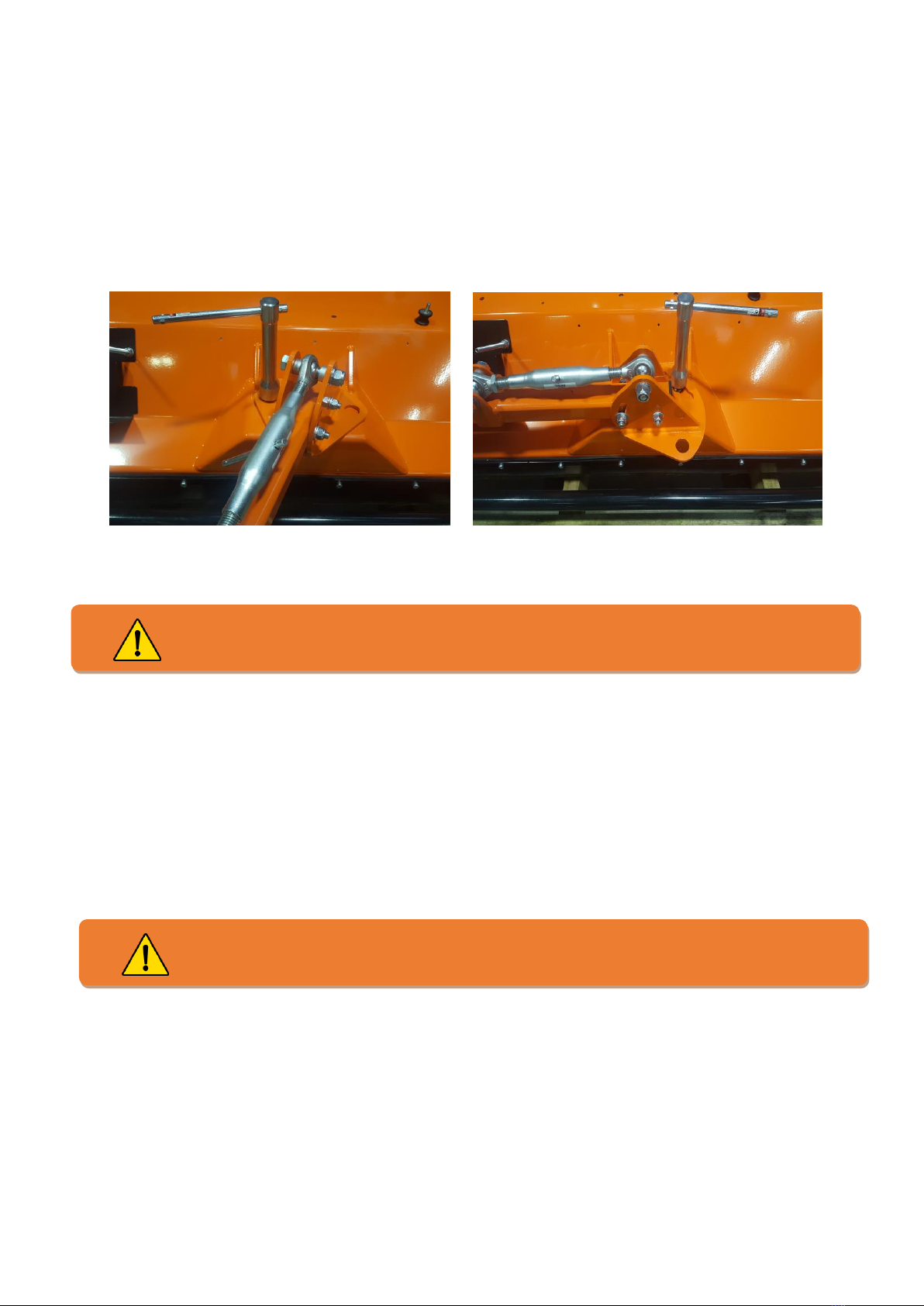
Offsetting
If required, the drawbar on the FM Series can be offset to the left or right or folded for storage.
The machine is offset by unscrewing the T-bar as shown below. The drawbar can then be moved to
the desired location, and the T-bar replaced in a suitable hole. The T-bar must be tightened firmly
to prevent movement of the drawbar and should be checked periodically for tightness.
Semi-offset Folded for storage
Starting Work
After ensuring all daily checks have been undertaken (see above), and with the engine throttle on idle setting
start the engine by turning the ignition key. Depending on the ambient temperature and engine temperature,
choke may be required. Once the engine is running and choke off, engage drive by increasing the engine
throttle to maximum.
Forward Speed
The forward working speed will depend greatly on the working conditions and nature of the material being
cut. Optimal speed will be in the region of 3-8 km/h (2-5 mph).
Changing the drawbar angle must be undertaken with the engine switched off & the
ignition keys removed. Failure to do so could result in injury or damage to the machine.
As the FM Series use a centrifugal clutch drive system, the engine must be run at maxi-
mum speed AT ALL TIMES when cutting.

Page 11
Drive Belts & Power Transmission
The FM Series Flail Mowers utilize two drive belts (2 x BX41 / 16 X 1115), driven through a centrifugal clutch, with a
spring tensioned idler system to compensate for wear of the belts and pulleys.
The drive belts are designed as a ‘weak-link’ in the drivetrain, such that the belts will fail before damage is caused to
the engine if a foreign object is encountered or rotor entanglement occurs. Drive belts are a wearing part and as
such are not covered by the machine warranty. NOTE: Always replace belts as a pair. Replace with ‘matched set’
belts which have a consistent belt length.
Belt Replacement
New Type Tensioner (09/14 - Present)
1. With the height at the highest setting, this should allow the easiest access without removing the wheels.
Alternatively, remove the wheel on the engine side, once the machine is suitably supported with chocks or
similar.
2. Remove the belt guard by loosening the 2 17mm bolts marked ‘B’, and fully removing the bolt marked ‘A’.
3. Slacken the tensioner adjuster bolt using two 17mm spanners, shown as part ‘C’ above. The tensioner adjuster
should be slackened to such a point as the spring can be removed by hand from the tensioner arm, as shown
by the right-hand image above.
4. At this point the tensioner arm will be free to rotate, allowing full access
to the belts. The belts can then be removed by ‘winding’ over the lower
pulley. Take care when removing / replacing belts not to lever the belt
or damage in any way, as this will greatly reduce belt life. The belts
should be able to be fitted by hand, without using any forcing tools.
5. Replacement is a reversal of removal. Belts should be tensioned to 5mm
deflection at 15kgf. As a rough guide each belt should deflect
approximately 5mm under medium thumb pressure applied at the
midpoint of the belt between the two pulleys. Both belts should deflect to
the same degree.

Page 12
Maintenance
All maintenance, cleaning and repair operations must be performed with the machine suitably supported, the
engine switched off (and cool), and the ignition keys removed.
NOTE: For commercial use, log hours of operation in a maintenance booklet to ensure proper maintenance
intervals and continued service.
Maintenance Schedule
After first 1 hours of work
•Check all nuts and bolt for tightness –retighten if required.
•Check belt tension and taper lock tightness –adjust / tighten if required
(refer to belt section for details of adjustment).
Every 8 hours or daily
CHECK
•Check all nuts and bolt for tightness –retighten if required.
•Check belt condition and replace if necessary
•Check wear and condition of flails –replacing missing, or damaged flails immediately.
•Check condition of safety guards –repair or replace if not performing their function.
•Check operation of emergency stop control
LUBRICATE
•Lubricate rotor bearings –Apply grease to the two main rotor bearings. See below for locations of the
•grease points.
•Lubricate rear roller bearings - Apply grease to the two rear roller bearings. See below for locations ofthe
grease points.
•Lubricate cross shaft bearings (Centre-mount only) - Apply grease to the two cross shaft bearings.See
below for locations of the grease points.
After every 100 hours (or annually, whichever occurs first), in addition to the above
CHECK
•Check belt condition - replace if required
•Check axle bearing condition - replace or lubricate as required
•Check rear roller condition - replace if required
•Check main rotor bearing condition - replace if required
•Check condition of battery & connections
•Check condition of fuel lines & replace if damaged or perished
•Check condition of battery cables - replace if worn.
•Check condition of flexible coupling (Centre mount models only)
•Check clutch operation (disengage at idle, engage at approx. 30% throttle)
Tyre Pressures
FM range - 22x11x8 0.50-0.82 bar (7-12 psi)
Page 13
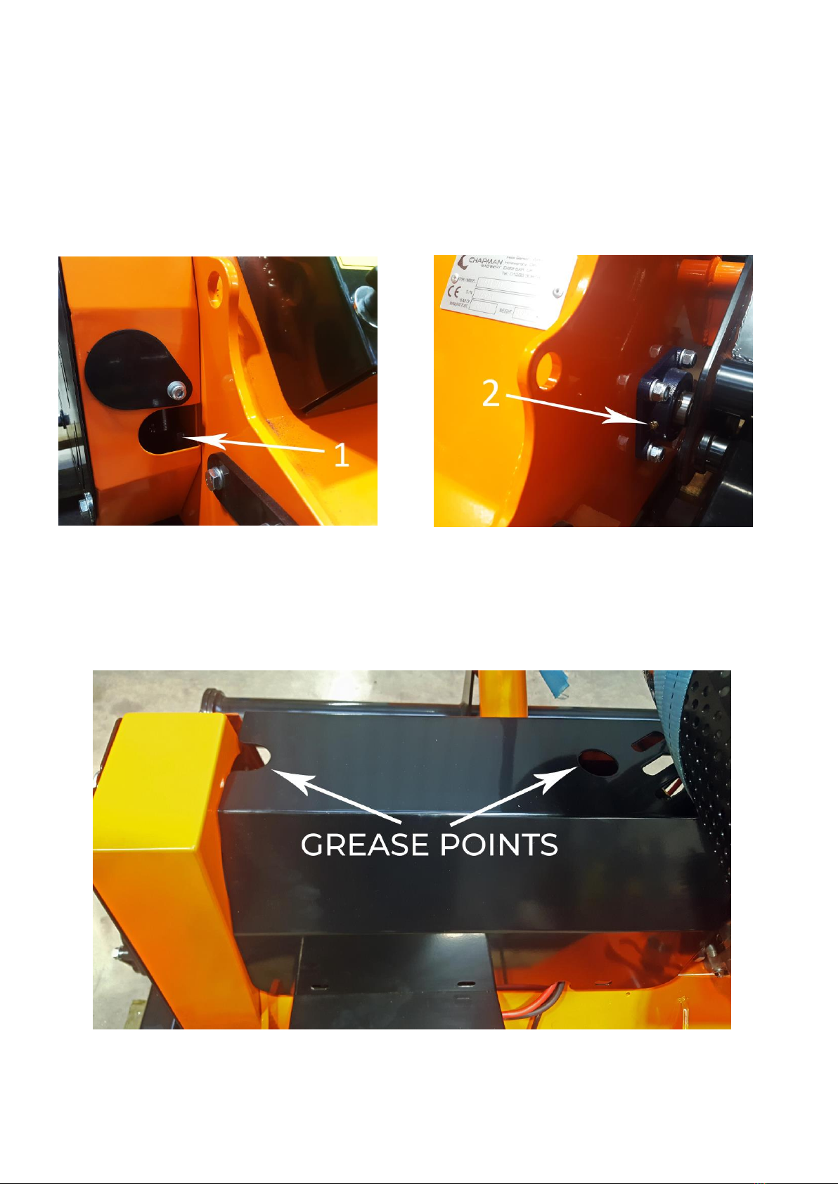
Maintenance Instructions
Grease Points
All Models:
Lubricate the following points using Multi-purpose lithium-based grease with NLGI 2 viscosity grease as per the
maintenance schedule:
1. Driven Side Rotor Bearing
2. Non-Driven Side Rotor Bearing
Centre-mounted engines only:

Page 14
Flail Condition & Replacement
Over time, the flails on your machine will wear, and performance will deteriorate. It is important that the flails are
kept in good condition to ensure a long service life of your machine. Flails should be replaced when either; 3mm
has worn off the end of the flail; the flail has become blunt or damaged; flails are missing.
When replacing flails the diametrically opposite flail should be replaced at the same time in order tomaintain rotor
balance, When flails are fitted in pairs, (e.g. Y Grass Flails), both must be replaced at the same time. As flails are
fitted in a spiral pattern care must be taken to replace the correct diametrically oppositeflails.
When replacing flails visually inspect the mounting bolts and bushes, if applicable. These are all wearing part and
normally should be replaced at the same time as the flails.
Troubleshooting
Problem Possible Causes Remedies
Irregular Cut
Worn, bent or broken flails
Inspect & replace & damaged flails
RPM too low
Always use maximum throttle
Machine not level to the ground
Check & adjust tyre pressures
Clogged material caused by exces- sive
forward speed
Reduce forward speed
Excessive Machine Noise
Unbalanced Rotor
Check flails & replace any damagedflails.If
vibrationpersists,see “vibration” below
Loose bolts
Check bolts & tighten as necessary
Damaged components
Repair or replace
Excessive Engine Noise
Worn muffler
repair or replace
Engine problems
Consult authorized dealer or
Chapman Machinery
Excessive Belt Noise
Belts slipping
Adjust belt tensioner
Belts worn
Replace belts
Vibration
Worn, bent or broken flails
Inspect and replace as necessary
Rotor out of balance
Balance or replace rotor
Worn rotor bearings
Replace rotor bearings
Excessive movement of drawbar
Worn drawbarpins
Replace drawbar pins
Loose drawbar hand screws
Tighten hand screws
Bearings tight or overheating
Bearings dirty or ungreased
Clean & grease bearings
Bearings worn to excess
Replace bearings
Belts Overheating
Belts slipping on pulleys
Tension belts
Flails contacting the ground
Raise cutting height
Working speed too high
Reduce forward speed
Machine Disposal
Disposal of this machine and any of its component parts must be performed in a responsible and inoffensive
manner respecting all current laws relating to this subject. Materials forming this machine that must undergo
differentiated division and disposal are:
Steel, Mineral Oil, Rubber & Plastic

Page 15
Warranty
The Chapman Warranty
Chapman Machinery Ltd (herein ‘Chapman’ or ‘Chapman Machinery’) warrants that the machine referred to in the Warranty Registration Form will be free
from manufacturing defects for a period of 24 months from the date of sale. This warranty does not affect your statutory rights, but merely adds to them.
Should you have a problem within 24 months from the date of sale please contact your original dealer, or Chapman Machinery’s Service Department.
Any part found to be defective during this period will be replaced or repaired, at our discretion, by the dealer or a authorised Service Engineer.
Warranty Conditions
1. The Warranty Registration Form must be completed and returned to Chapman Machinery Ltd within 30 days of the date of sale
2. This warranty does not cover defects arising from fair wear and tear, wilful damage, negligence, misuse, abnormal working conditions, use in competition,
failure to follow Chapman Machinery’s instructions (oral or written, including all instructions and recommendation made in the Operator’s Manual) or
alteration or repair of the
machinery without prior approval.
3. The machinery must have been serviced in accordance with the Operator’s Manual and the Service Log must have been
kept up to date and made available tothe
dealer should service, repair or warranty work be undertaken.
4. This warranty does not cover claims in respect of wearing parts such as blades, flails, paintwork, tyres, belts, hydraulic hoses, bearings, bushes, linkage
pins, top links, ball ends unless there is a manufacturing or material defect or the cost of normal servicing items such as oils and lubricants.
5. This warranty does not cover any expenses or losses incurred whilst the machinery is out of use for warranty repairs or parts replacement.
6. This warranty does not extend to parts, materials or equipment not manufactured by Chapman Machinery, for which the Buyer shall only be entitled to the
benefit of any such warranty or guarantee given by themanufacturer to Chapman Machinery. Only genuine replacement parts will be allowable for warranty
claims.
7. All parts replaced by Chapman Machinery under warranty become the property of Chapman Machinery and must be returned to Chapman Machinery if
so requested. Such parts may only be disposed of after a warranty claim has been accepted and processed by Chapman Machinery.
8. Chapman Machinery is not liable under this warranty for any repairs carried out without Chapman Machinery’s written consent or without Chapman
Machinery being afforded a reasonable opportunity toinspect the machinery the subject of the warranty claim. Chapman Machinery’s written consent must,
therefore, be obtained before any repairs are carried out or parts replaced. Use of non- Chapman Machinery parts automatically invalidates the Chapman
Warranty. Failed components must not be dismantled except as specifically authorised by Chapman Machinery and dismantling of any components without
authorisation from Chapman Machinery will invalidate this warranty.
9. All warranty claims must be submitted to Chapman Machinery on Chapman Machinery Warranty Claim Forms within 30 days of completion of warranty
work.
Using the machine implies the knowledge and acceptance of these instructions and the limitations contained in
this Manual.
Transfer of Warranty
The Chapman warranty be transferred to a subsequent owner of the machinery (for use within the UK only) for the balance of the warranty period subject to
all of the stated warranty conditions and provided that the Change of Owner form is completed and sent to Chapman Machinery within 14 days of change of
owner- ship.
Chapman Machinery Ltd retain the right to refuse transfer of warranty.
Chapman Machinery reserves the right to make alterations and improvements to any machinery
without notification and without obligation to do so.

Page 16
EU DECLARATION OF CONFORMITY
Machinery Directive 2006/42/EC
Chapman Machinery Ltd
Hele Barton
Week St. Mary
Holsworthy
Devon
EX22 6XR
The Products Covered by this Declaration
Product: FM Series Flail Mowers& Options
Standards and Regulations used: MachineryDirective2006/42/EC
PlaceofIssue: United Kingdom
Nameof Representative: James Chapman
Position of representative: Director
The Basis on which Conformity is being Declared
I declare that as the authorized representative, the above information in relation to the supply / manufacture of
this product, is in conformity with the stated standards and other related documents following the provi- sions of
Machinery Directive 2006/42/EC directives
The products described above comply with the essential requirements of the directives specified.
Signed:
Date: ......13/05/2011..................
This manual suits for next models
4
Table of contents


