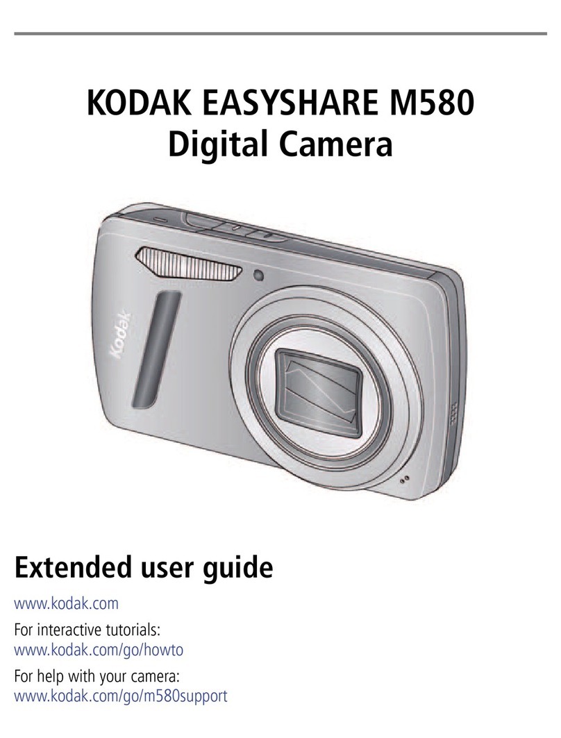
CheckVideo CV120 Manual

Things You Need for Installaon
Step One Connect Camera to Router
CheckVideo Outdoor/Indoor Camera Installaon Quick Reference
Step Two Create/Access Your Account
Step Four Add Camera to Wireless Network
1. Go to the CheckVideo Dashboard login page:
portal.checkvideo.net
Click the Start here link to create your account.
If you have an exisng account, log in and skip to the next
secon to register your CheckVideo devices.
2. Complete the User Informaon secon.
3. In the Dene Nocaon Methods secon, for Contact
Informaon enter the email addresses that may receive event
nocaons. For MMS nocaons to mobile phones, the
address format will vary by carrier (ex: mobile number@
Fig. 2 - Add Device: Enter device serial number
To use the CheckVideo Outdoor/Indoor Camera with a wireless network:
1. Go to portal.checkvideo.net and select Devices > Wi-Fi setup
2. Choose camera from System Map.
3. Conrm Network Name and Security Type.
4. Enter Network Security Key and click Apply.
Fig. 1 - CheckVideo Outdoor/Indoor Camera’s power and Ethernet connectors
Ethernet connector
power connector
LED
1. Connect the CheckVideo Outdoor/Indoor Camera to your
wireless router using its Ethernet connector. (You’ll discon-
nect it from the router later in the setup process.)
2. Connect the Camera to the power supply and plug it in.
3. Wait for the LED light on the boom of the Camera to turn
green (this may take several minutes).
Included in the box:
• CheckVideo® Outdoor/Indoor Camera, with
Power Supply
• Mount, Mount Base, and Screws (4)
• MicroSD Card
• (Oponal) Ethernet Adapter
You’ll also need:
• PC or Mac® with Broadband Internet Service
• Wireless Router, connected to the Internet
• Phillips Screwdriver
• Sloed Screwdriver
1. If camera will be monitored by a central staon, contact them to
add the device to their account.
2. If self-monitored:
• On the CheckVideo Dashboard, click on Devices > Add Device.
• In the Register Device secon, enter the serial number found
on the camera tag and a Device Name.
• Click the Test Device buon to make sure the CheckVideo
Soware Service (CVSS) can communicate with the device.
• (Professional Service only) Authorize service fees.
• If prompted, update the device rmware.
Step Three Add CheckVideo Outdoor/Indoor Camera
mms.a.net). Check your carrier’s website for more informaon.
4. Choose a maximum Video Resoluon for each email address. If
you intend to use MMS to send video to a mobile phone, do not
select a resoluon higher than 480p. For 720p or 1080p, send the
nocaons as an aached video clip to a tradional email address
(ex: [email protected]). Use the Test buon to conrm that the video
resoluon is valid for your device/carrier.
5. In the Billing Preferences, choose your Service opon. If you choose
Central Service, complete the form and CheckVideo Support will contact
you directly.
6. (Professional Service only) Specify method of payment, authorize service
fees, and accept the License Agreement.
If this CheckVideo device will be monitored
by a central staon, please contact the central
staon for a username and password on their
exisng CheckVideo account. The central
staon will add the device to their account. If
this device will be self-monitored, you will be
creang a CheckVideo account in Step Two.
5. To congure addional cameras choose from the System Map
and click Apply.

Step Five Assemble Camera
Step Six Install Camera
Step Seven Conguraon
Fig. 9a - A zone, dened by eight end points
(rst point is green; other points are blue) Fig. 9b - A completed zone
1. On the CheckVideo Dashboard, click on Devices > Cong-
ure Device.
2. Select Device: Select the device and video resoluons
for event clips and DVR. CheckVideo will default both
resoluons to 240p. You may wish to start with these
sengs. Your chosen resoluon sengs will depend upon
the upload capacity of your Internet provider.
3. Congure Events: Click the Edit buon to create a zone
for a parcular object type. Then use your mouse to draw
the zone by clicking the le mouse buon wherever you
want to dene a point of the zone. The zone should cover
the enre area where you want to detect an event. Enter
a me span, event type, zone, and duraon and click Add
Event buon.
For more detailed informaon, refer to the CheckVideo Camera
Installaon Guide available at www.checkvideo.com.
© 2015 CheckViideo, LLC.
CheckVideo is a registered trademark of CheckVideo, LLC. All rights reserved.
7CVCCQD000E-04.01
Fig. 6 - MORE EFFECTIVE: Cameras
are at a 15 to 45 degree downward
lt and are mounted 8 to 20 feet high
Fig. 7 - LESS EFFECTIVE: Cameras are
directly overhead (90 degrees) or parallel
to (0 degrees) the target
To opmize event detecon, place your CheckVideo Outdoor/Indoor
Camera as follows:
• HEIGHT: Each camera must be installed 8 to 20 feet o the
ground.
• DISTANCE: If you are mainly detecng people, the distance
between the camera and the people you wish to detect should
be 10 to 40 feet. If you are primarily concerned with detecng
vehicles, the range is 20 to 60 feet.
The CheckVideo Camera Placement Guide includes a summary
checklist on improving your camera placement.
Once you’ve determined where to place the Camera, conrm it can
receive a signal from your wireless router. Power it up and see if the
LED light turns green. If there is no wireless signal, the LED will turn
orange within two minutes.
The Camera can be placed on a ceiling, wall, or shelf.
Loosen the nuts to adjust the mount arm to the desired posion.
Use the three long screws to aach the Camera to your selected
locaon.
Fig. 8 - Adjustment nuts (le); using screws to aach mount/mount base to surface
Nuts Screws
Fig. 4 - Remove the nut and stud from the rotang joint to expose the
screw inside the joint. Using a sloed screwdriver, aach the rotang
joint to the Camera by securely ghtening the screw. Slide the mount
into the rotang joint and then secure the stud into place with the
nut. The head of the stud should rest in the recessed side of the joint.
ABC
rotang joint rotang joint
screw
nut
stud
Fig. 5 - Remove the Ethernet adapter from inside the
mount base. Gently pull the rubber gasket away from
the base. Press the cable aached to the Camera
down through the right-hand slot. Connect the two
cables inside the base. Press the tab into the center
tab of the gasket to close it and re-insert the gasket.
rubber gasket
le-hand
slot
power cable
mount base
cable
Fig. 3 - Insert the microSD card into the slot
with the “teeth” of the card facing the front
of the device. Close the door securely.
If using an Ethernet connecon, the assembly will be dierent. See the Installaon Guide for more informaon.
door
Small Screw
,
Make sure your browser is set to 100% when drawing
your zone.
4. Select Nocaon Method - Central Staons: Select a Central Staon type that
should receive alert metadata.
5. Select Nocaon Method - Users: Click the checkbox next to any user(s) who
should receive nocaons for this camera and their method of nocaon.
6. Click Save.
Table of contents


