ChefLine EV-SPE904-LS User manual

EN CONVECTION OVENS
INSTRUCTIONS FOR THE INSTALLATION, USE AND MAINTENANCE
IT FORNI A CONVEZIONE
ISTRUZIONI PER L’INSTALLAZIONE, L’USO E LA MANUTENZIONE
DE HEISSLUFTÖFEN
ANLEITUNGEN FÜR DEN INSTALLATEUR, BEDIENUNGS-UND WARTUNG
FR FOURS À AIR PULSE’
INSTRUCTIONS POUR L’INSTALLATION, L’EMPLOI ET LA MAINTENANCE
ES HORNOS A CONVECCIÓN
INSTRUCCIONES PARA LA INSTALACIÓN, USO Y MANTENIMIENTO
NL CONVECTIEOVENS
INSTRUCTIES VOOR DE INSTALLATIE, GEBRUIK EN ONDERHOUD
B02.0009.00
NB-SP-004E
NB-SP-006E
NB-SP-010E
E104-UPE
E106-UPE
E110-UPE
E604-UPE
E606-UPE
E610-UPE
FMLD423
FMLD443
FMLD461
FMLD661
FMLD1061
EV-SPE904-LS
EV-SPE906-LS
EV-SPE910-LS
GUP-304EB
GUP-404EB
GUP-104EB
GUP-604EB
GUP-004EB
GUP-106EB
GUP-606EB
GUP-006EB
GUP-110EB
GUP-610EB
GUP-010EB

EN INDEX IT INDICE DE INHALT
Dimensions Dimensioni Abmessungen
Foreword Premessa Vorwort
1.0 Declaration of Conformity Dichiarazione di conformità Konformitätserklärung
1.1 European Directive
ROHS 2012/19/UE Direttiva Europea
ROHS 2012/19/UE Europäische Richtlinie
ROHS 2012/19/UE
1.3 Transport of the oven and
packaging removal Trasporto del forno e rimozione
degli imballi Transport des Ofens und
Entfernung der Verpackung
1.4 Informative labels Targhette informative Informationsetiketten
INSTALLATION INSTALLAZIONE INSTALLATION
1.5 Oven positioning Posizionamento del forno Positionierung des Ofens
1.6 Electrical connection Collegamento elettrico Elektroanschluss
1.7 Technical data for electrical
connection Tabella dati tecnici allacciamento
elettrico Tabelle technische Daten Elektro-
anschluß
2.5 Hydraulic connection
water inlet Collegamento idraulico
entrata acqua Anschluss ans Wassernetz
Wasserzufuhr
3.1 Spare parts replacing Sostituzione parti di ricambio Austausch der ersatzteile
3.2 Checking the functions Controllo delle funzioni Kontrolle der funktionen
USE AND MAINTENANCE USO E MANUTENZIONE BEDIENUNGS-UND WARTUN-
GSANLEITUNG
4.0 Description of the control panel
components Descrizione componenti pannello
comandi Programmierung und Betrieb
4.5 Starting the oven Avviamento del forno Steuerung und
Kontrollvorrichtungen
4.6 Turning the oven o Spegnimento del forno Ausschalten des Gerätes
9.0 Maintenance Manutenzione Wartung
9.1 What to do in the case of a brea-
kdown or non use Comportamento in caso di guasto
e/o prolungato inutilizzo
Anweisungen bei Störungen und/
oder längerem
Gerätestillstand
10.1 Remedies to cooking hitches Rimedi alle anomalie di cottura Abhilfe bei anormalem Garen
2

FR INDEX ES INDICE NL INHOUDSOPGAVE
Dimensions Dimensiones Afmetingen
Avant-propos Premisa Introductie
1.0 Déclaration de conformité Declaración de conformidad Verklaring van conformiteit
1.1 Directive européenne
ROHS 2012/19/UE Directiva Europea
ROHS 2012/19/UE Europese Richtlijn
ROHS 2012/19/UE
1.3 Transport du four et élimination
de l’emballage Transporte del horno y remoción
de los embalajes Transport van de oven en verwij-
deren van de verpakking
1.4 Etiquettes informatives Tarjetas informativas Informatieve etiketten
INSTALLATION INSTALACIÓN INSTALLATIE
1.5 Positionnement du four Posicionamiento del horno Het plaatsen van de oven
1.6 Raccordement électrique Conexión eléctrica Elektrische aansluiting
1.7 Tableau des données techniques
raccordement électrique Tabla datos técnicos de
conexión eléctrica Tabel technische
gegevens - elektrische
aansluiting
2.5 Raccordement hydraulique - arri-
vée d’eau Conexión hídrica-entrada del
agua Wateraansluiting – waterinlaat
3.1 Remplacement des pièces Piezas de recambio Vervanging reserveonderdelen
3.2 Contrôle des fonctions Control de las funciones Controle van de functies
EMPLOI ET MAINTENANCE USO Y MANTENIMIENTO GEBRUIK EN ONDERHOUD
4.0 Description des éléments du
panneau Descripción componentes panel
de mandos Beschrijving van componenten
bedieningspaneel
4.5 Commandes et contrôles auxi-
liaires Encendido del horno Starten de oven
4.6 Arrêt du four Apagado del horno Het uitschakelen van de oven
9.0 Maintenance Mantenimento Onderhoud
9.1 Que faire en cas de panne ou
d’arrêt prolongé de l’appareil Comportamiento en caso de
avería o de larga inactividad Handelen in geval van
storingen
10.1 Que faire pour résoudre les pro-
blèmes de cuisson Remedios para las anomalías de
cocción Oplossingen voor problemen bij
het koken

4 x 2/3 GN - 4 x 460x340
Dimensioni Capacità Distanza teglie Peso a vuoto
Dimensions Capacity Trays distance Empty weight
Abmessungen Kapazität Einschubabstand Leergewicht
Dimensions Capacité Ecartement grilles Poids à vide
Dimensiones Capacidad Distancia bandejas Peso en vacío
Afmetingen Capaciteit Afstand dienbladen Leeggewicht
mm 722 x 742 x h 564 4 x 2/3 GN
4 x 460x340 75 mm 40 kg
4
17
48958
116490116
722
414
619
663 17
680
101
403
497
742
61
1260
12045011061
742
61
A
B
C
D
B
C
A
247475
249

4 x 1/1 GN - 4 x 60x40 - 4 x 1/1 GN 60x40
Dimensioni Capacità Distanza teglie Peso a vuoto
Dimensions Capacity Trays distance Empty weight
Abmessungen Kapazität Einschubabstand Leergewicht
Dimensions Capacité Ecartement grilles Poids à vide
Dimensiones Capacidad Distancia bandejas Peso en vacío
Afmetingen Capaciteit Afstand dienbladen Leeggewicht
mm 862 x 742 x h 564
4 x 1/1 GN
4 x 60x40
4 x 1/1 GN - 60x40
75 mm
5
17
489
58
116630116
862
414
619
663 17
680
101
487
581
742
61
1399
12045011061
742
61
A
B
C
D
B
C
A

6
6 x 1/1 GN - 6 x 60x40 - 6 x 1/1 GN 60x40
Dimensioni Capacità Distanza teglie Peso a vuoto
Dimensions Capacity Trays distance Empty weight
Abmessungen Kapazität Einschubabstand Leergewicht
Dimensions Capacité Ecartement grilles Poids à vide
Dimensiones Capacidad Distancia bandejas Peso en vacío
Afmetingen Capaciteit Afstand dienbladen Leeggewicht
mm 870 x 770 x h 714
6 x 1/1 GN
6 x 60x40
6 x 1/1 GN - 60x40
75 mm
17
639
58
120630120
870
414
647
691 17
708
101
491
585
770
61
12048810061
770
61
A
B
C
D
B
C
A
255615
277
1435

7
10 x 1/1 GN - 10 x 60x40 - 10 x 1/1 GN 60x40
Dimensioni Capacità Distanza teglie Peso a vuoto
Dimensions Capacity Trays distance Empty weight
Abmessungen Kapazität Einschubabstand Leergewicht
Dimensions Capacité Ecartement grilles Poids à vide
Dimensiones Capacidad Distancia bandejas Peso en vacío
Afmetingen Capaciteit Afstand dienbladen Leeggewicht
mm 870 x 770 x h 1014
10 x 1/1 GN
10 x 60x40
10 x 1/1 GN - 60x40
75 mm
17
93958
120630120
870
414
647
691 17
708
101
491
585
770
61
12048810061
770
61
A
B
C
D
B
C
A
255615
277
1435

8
FOREWORD
The contents of this manual are generic and not all the functions described may be available on your
product.
The manufacturer declines all responsibility for possible inaccuracies contained in this pamphlet, due to printing
or copy errors. We reserve the right to make on our own products those changes to be considered necessary or
useful, without jeopardizing the essential characteristics.
Read the instructions for use very carefully paying particular attention to the rules concerning safety devices. This
appliance must only be used for what it has been designed for and built for and that is: all baking of dishes and
regenerating pre-cooked and/or frozen food.
WARNING!
Before making any type of connection of this equipment (electrical or hydraulic), carefully read the instructions
in this manual. This manual must be carefully kept to be available for future reference by users or service tech-
nicians. Installation must be carried out by d qualied personnel only.
1.0 DECLARATION OF CONFORMITY
The Manufacturer declares that the appliances conform to the EEC norms.
They must be installed in accordance with current standards, especially regarding aeration of the premises and
the exhaust gas evacuation system.
Note: The Manufacturer declines all and every responsibility for any direct damages caused by: an
incorrect use, wrong installation or bad maintenance.
1.1 EUROPEAN DIRECTIVE ROHS 2012/19/UE
This appliance is marked according to the European directive 2012/19/UE on Waste Electrical and Electronic
Equipment (WEEE). By ensuring this product is disposed correctly, you will help prevent potential negative con-
sequences for the environment and human health, which could otherwise be caused by inappropriate waste han-
dling of this product.
The symbol on the product, or on the documents accompanying the product, indicates that this
appliance may not be treated as household waste.
Instead it shall be handed over to the applicable collection point for the recycling of electrical
and electronic equipment.
Disposal must be carried out in accordance with local environmental regulations for waste dis-
posal.
1.3 TRANSPORT OF THE OVEN AND PACKAGING REMOVAL
Upon receipt of the oven and before installing it, check the packaging is intact and there are not visible damages.
Also check that along with the oven you receive also the documentation, consisting of:
• Instructions for installation, use and maintenance
• Chart to check correct installation
• Wiring diagram
• Label ISO 3864-1
Before bringing the oven to the point, where it must be installed, check the following:
The doors are large enough to allow passage of the oven
The oor supports the weight.
According to the model of oven, its dimensions and its weight, use suitable facilities to handle goods during trans-
port and installation, able to guarantee stability in order to avoid overturning, falls or uncontrolled movements of
the appliance or its components.
Keep the oven packed until you reach the site where the oven is going to be installed.
The packaging makes the handling of goods easier and protects the oven from accidental push.
During moving and installation of the oven, the installer must comply with accident-prevention regulations in
force at the place of installation (use of safety shoes, gloves, etc.) Remove the packaging taking care not to dam-
age the oven. The adhesive lm, that protects the surfaces made of stainless steel can be removed also after you
have positioned the oven on the corresponding stand or the support surface.
ATTENTION: Packaging materials and adhesive lm are potentially dangerous.
For this reason, they must be kept out of the reach of children and properly disposed of in com-
pliance with local directives.
You should separate packaging materials (wood, cardboard, plastic...) and dispose of them se-
parately, in compliance with directives in force at installation site.
Note: Take the protective lm o the stainless steel parts by hand before starting the appliance.
Do not use abrasive substances and/or metal objects. Clear any adhesive residues using a sponge soaked in sol-
vent. If the oven is heated up before removing the adhesive lm, the removal of the lm and cleaning of residues
of glue will be much more dicult.
EN

9
1.4 INFORMATIVE LABELS
On each oven there are applied some metal labels, that give important info concerning characteristics of the oven,
electric and plumbing connections and eventually the drain connection.
On the right hand side panel there is the label A.
The info contained on this label are:
• Name and address of the manufacturer
• Oven model
• IPX protection grade against water jet.
• Conformity to EC directives.
• Power input and power supply (single or three phase).
• Serial number of the oven
• Symbol of European Directive 2012/19/UE
Removing the back side panel, on the oven chassis you nd label B.
On this label the serial number of the oven is repeated.
In this way, the customer or the installer can nd the serial number of the
oven also when the label A is dirty or damaged.
If the oven is equipped with humidication, in the back of the oven, near the
connector for water connection there is the label C.
Label C indicates water features necessary for a correct functioning of the
oven.
Same features are listed at paragraph 2.3A of this manual.
INSTALLATION
1.5 POSITIONING OF THE OVEN
The place where the oven will be installed must comply the following requirements:
• Be protected from atmospheric agents and have an adequate air circulation;
• Comply with regulations concerning safety at work;
• Have a room temperature between 5 °C and 35 °C with a humidication not higher than 70%.
• Place the oven and proceed with levelling using adjustable feet.
•
Keep a suitable distance at the back, in order the label of equipotential clamp is easy to see when the oven has
been installed. The same clamp must be easy to access to install equipotential cable after the oven has been
installed in compliance with our instructions.
Install the appliance in a position that allows access to the right side for installation, maintenance and technical
assistance.
1.6 ELECTRICAL CONNECTION
When the appliance is delivered it is set to work at the voltage given on the rating plate axed on the right side
of the appliance.
The eectiveness of the equipotential system of which the appliance is part of, must conform to current stand-
ards.
Connect using the screw you nd in the back side of the oven, marked with the word EQUIPOTENTIAL.
The Manufacturer declines all and every responsibility if this important accident prevention norm is not complied
with. If the feeding cable is damaged, it must be replaced by the technical service or in any case by similar qual-
ied personnel, in order to avoid any risk.
EN

10
EN
1.7 TECHNICAL DATA FOR ELECTRICAL CONNECTION
Model Power loading
and voltage no. and motor
power Heating
power Absorbed
current Feed cable
section
4 x 2/3 GN 3.3 kW
220-240 V 1N ~
50/60 Hz 1 x 240 W 3.0 kW 14.0 A cable included
4 x 460x340
4 x 1/1 GN 3.3 kW
220-240 V 1N ~
50/60 Hz 1 x 240 W 3.0 kW 14.0 A cable included
4 x 60x40
6.5 kW
380-415 V 3N ~
50/60 Hz 2 x 240 W 6.0 kW 11.0 A 5 x 2.5 mm2
4 x 1/1 GN
4 x 60x40
6 x 1/1 GN
7.9 kW
380-415 V 3N ~
50/60 Hz 2 x 240 W 7.4 kW 13.5 A 5 x 2.5 mm2
6 x 60x40
6 x 1/1 GN
6 x 60x40
10 x 1/1 GN
11.9 kW
380-415 V 3N ~
50/60 Hz 3 x 240 W 11.1 kW 20.0 A 5 x 4.0 mm2
10 x 60x40
10 x 1/1 GN
10 x 60x40

11
2.5 HYDRAULIC CONNECTION – WATER INLET
If the humidication system is installed, the ovens have a water inlet coupling at the back.
Always install an on-o valve between the appliance and the water mains, making sure it is easy to operate.
We also suggest installing a cartridge lter on the water inlet pipe.
Always use a set of new water joints, eventual old joints must not be used again.
Plumbing connection must be always eected with cold water and rigid pipes.
Never use hoses to connect the oven to the water main.
The water must be suitable to human use with the following characteristics:
Temperature: included between 15 – 20°C
Total hardness: included between 4 and 12 °f (French degrees), it is advisable to install a softener upstream
from the appliance that will maintain the hardness level at the mentioned values.
Pressure: included between 150 and 250 KPa (1,5 – 2,5 bar).
Attention: higher water pressure values result in increased water consumption and can compromise
the correct functioning of some components.
Maximum chloride concentration (Cl-): less than 150 mg/litre.
Chlorine concentration (Cl2): less than 0.2 mg/litre.
pH: more than 7.
Water conductivity: included between 50 and 2000 µS/cm.
Attention: Water treatment systems that bring to dierent values to the ones above mentioned au-
tomatically invalidate the guarantee.
The use of dosing systems designed to prevent the build-up of lime-scale in pipes (i.e. polyphosphate dosing
systems) is also prohibited since it may impair the performance of the appliance.
3.1 REPLACING SPARE PARTS
The replacement of damaged parts must be done only by qualied personnel.
To request the manufacturer parts to be replaced must be provided the oven model and serial number.
These data can be found on the rating plate attached to the oven (see par. 1.4).
Before starting to replace spare parts make sure, for safety reasons, that the electricity main switch is o
and that the water on-o valve are closed.
3.2 CHECKING THE FUNCTIONS
After completing the installation of the oven is necessary to perform a leak test to the water network.
The installer must check with suitable measurement instruments that the air noise emissions have
a level of sound pressure type weighed A, less than 70 dB (A).
The label ISO 3864-1 here on the side must be stuck on a visible surface, 1,6 mt
height from the ground.
On oor models, the label is already stuck in the suitable position.
On table models, the label is supplied along with the documentation and must be
stuck after installation on a visible part of the appliance at 1.60 mt from the ground.
The installer must verify proper operation of the oven, providing the necessary instructions
to the customer and give this instruction manual that the user must follow carefully.
IMPORTANT:
Before the operator turns the oven on and uses it for any cooking or washing cycle, it is necessary that the install-
er or a qualied technician checks all the connections have been done up to the instructions stated in our manual.
The technician or the installer must therefore check as follows:
• The oven must stand (horizontal position) and be xed on a stand or a shelf, that can guarantee stability.
• Wiring connection must be eected according to the directives and the feed cable section must be no lower than
the one indicated in the manual.
• Pressure and hardness of the water must comply the values indicated in this manual;
• If the oven is supplied with drain pipe, this must be connected properly and the materials used should withstand
the working temperature.
After you have checked everything, open the water on-o valve, eventually the gas on-o valve and the protec-
tion switch, all installed upstream.
The installer must check the proper functioning of the oven and give to the operator necessary instructions for a
correct use of the oven, and also verify that the operator owns a copy of this manual.
At the end the installer must ll in and sign the chart for correct installation and give it to the custo-
mer, who will keep it for all warranty period of the oven.
EN
12
USE AND MAINTENANCE
INSTRUCTIONS FOR A SAFE USE OF THE OVEN
• Ensure the oven is on a stable position and safety devices installed upstream are ecient.
• Always use adequate protection gloves to introduce or pull out the trays.
• Always pay maximum attention to the oor, that due to cooking steam could be slippery.
• In order to avoid burns, never use trays or containers with liquids or uids over a level that can be easily
controlled at sight.
• Don’t put trays or other kitchen tools on the oven.
• Periodically have a check with technical service and replace eventual damaged parts, that could alter the
proper functioning of the oven or be a danger.
• Often clean the oven following the instructions stated in this manual.
MAX. FOOD LOADING
Number of trays Max. food loading
4 x 2/3 GN - 4 x 460x340 8 kg
4 x 1/1 GN - 60x40 13 kg
6 x 1/1 GN - 60x40 18 kg
10 x 1/1 GN - 60x40 30 kg
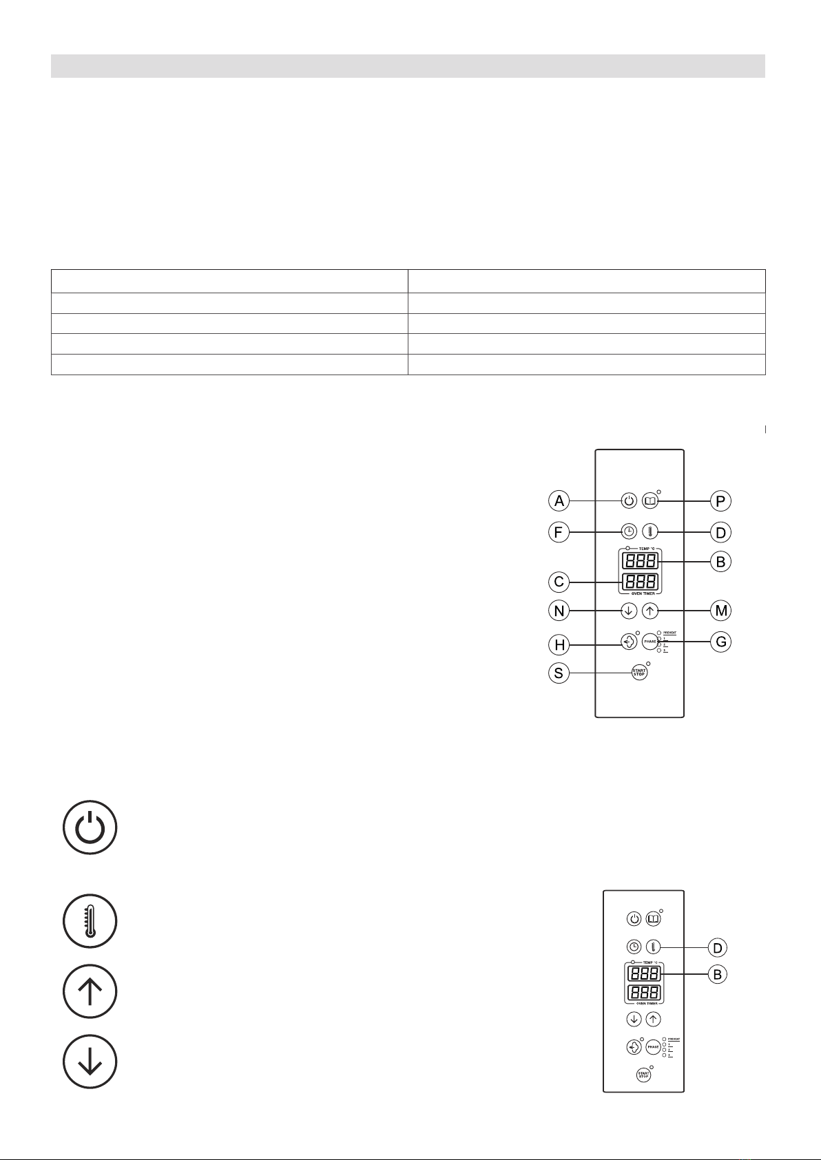
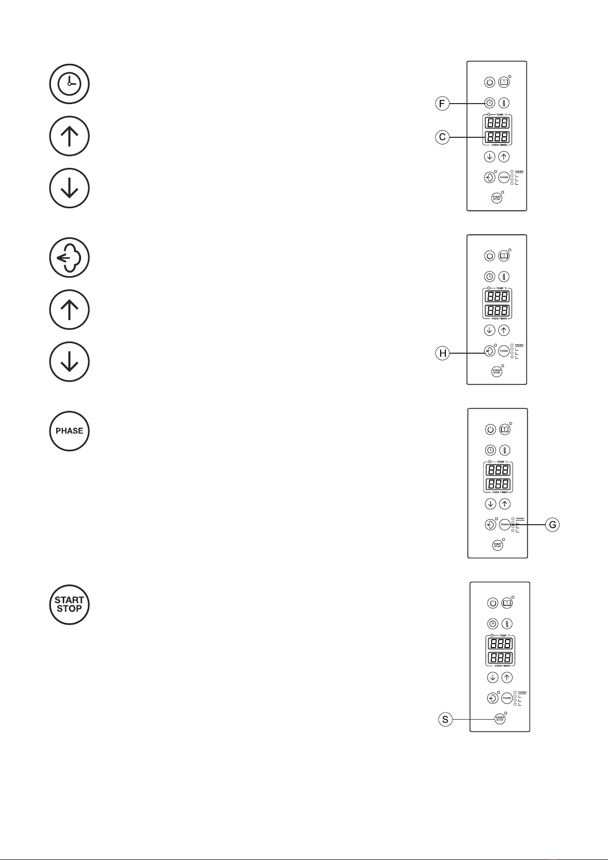
4.0 CONTROL PANEL COMPONENTS DESCRIPTION
AON/OFF button
BTemperature display
CTime display
DCooking chamber temperature selection
FTime selection
GCooking programs phases
HManual humidication/ humidication percentage button
MIncrease value button
NReduce value button
PAutomatic programs
SStart/stop button
4.2 STARTING THE OVEN
Switch on the water interception valves and the protection electric switch, installed upstream.
Press ON/OFF button to turn on the display.
ATTENTION! Switching o the oven with ON/OFF button does not interrupt the power supply to the
electronic boards. If the oven is not used, we advise you to switch o electric power supply using the
protection switch upstream.
4.5A COOKING CHAMBER TEMPERATURE
Display B shows the temperature of the cooking chamber. Pressing
temperature button (D), the display starts ashing and shows the
values set.
Press the button shown on the side to increase the value on the
display.
Press the button on the side to reduce the value on the display.
Press again temperature button (D) to store the new value for the
cooking. The led stops ashing.
The temperature range of the cooking chamber is 30 - 270 °C.
EN
EN
13
4.5B COOKING TIME
Press button (F) on the side to change cooking time. Display C
shows ---.
Press the button on the side to increase the value on the display.
Press the button on the side to reduce the value on the display.
For an unlimited functioning of the oven (innite time), press the
button on the side, when the display shows value 0. The display
will then show - - -.
4.5C HUMIDIFICATION PERCENTAGE
Press the button on the side to change humidication percentage.
Press the button on the side to increase the value on the display.
Press the button on the side to reduce the value on the display.
Press again humidication button to switch o the ashing led and
store the new value for the cooking. The humidity percentage ran-
ge is: 0% - 20% - 40% - 60% - 80% - 100%
4.5D ADDING COOKING PHASES
When a cooking parameter is conrmed, led 1 next to phases but-
ton G ashes for some seconds.
During this time it is possible to add a cooking phase, pressing button G.
You can set 3 phases maximum.
4.5E STARTING A MANUAL COOKING
Pressing button S (start/stop), the preheating phase starts.
The lower display shows the word PrE.
The leds PREHEAT next to PHASE button and the led next to START/STOP but-
ton turn on.
When set preheating temperature is reached, the buzzer starts ringing to advise
the end of the preheating. On the lower display the writing “PrE” ashes to-
gether with the preheating led.
The oven will maintain the preheating temperature until the door is opened to
load the food. When the door is closed, the cooking starts with phase 1.
If the door is opened during preheating (before reaching the set preheating temperature), preheating is auto-
matically interrupted, as it is presumed the food has been loaded into the oven.
During preheating it is not possible to use automatic humidication, whereas manual humidication is available.

14
EN
4.5F MANUAL HUMIDIFICATION
Manual humidication can be activated while cooking by pressing
button H.
The valve that injects steam in the cooking chamber is activated
only when button H is pressed.
It is possible to change the parameters during the cooking in order to adapt it
to the food.
4.6A AUTOMATIC COOKING PROGRAMS
You can store up to 99 programs, from P01 – to P99. There are 3
phases for each program. 3 leds indicate the working phase (or the
phase that is being set).
For each phase can be set:
- temperature
- time
- humidication
The oven is supplied with preset but not congured programs.
To search a program, select the programs list (not during a cooking) with
button P (pressing it slightly). The led next to button P is ashing, the upper
display is turned o and the lower shows the name of the program (P01…P99).
Using the buttons with arrows you can go up and down the list. To conrm the
chosen program, press again button P. The display shows the standard screen,
the led next to button P is on and the lower display shows the number of the
selected program. The cooking parameters of each phase can be changed. Pres-
sing Start, the preheating of the selected program starts.
4.6B STORING A PROGRAM
To store a program after selecting and modifying it, press button
P for 5 seconds with the number of the program shown on the
display.
The storing is conrmed by program leds ashing for some seconds. If the
display shows phases settings, you need to press P to change view and then
again for 5 seconds to store the program.
4.6C DELETING A PROGRAM
To delete a program when it is shown in the programs list, press for long and
simultaneously buttons F and D.
The deleted program becomes empty (not written) and it is stored.
4.6B QUITTING AUTOMATIC PROGRAMS
To go back to manual cooking, press ON/OFF.
4.7 SWITCHING OFF THE OVEN
To switch o the oven, press ON/OFF for some seconds (until the display turns o).

15
9.0 MAINTENANCE
All external stainless steel parts should be:
1 - cleaned with clear, soapy water;
2 - rinsed with water;
3- dried thoroughly.
It is absolutely forbidden to use scrapers, metal soap pads and other common steel tools as they could besides
scratching the surface, deposit iron particles that, oxidizing would cause rust to form.
DO NOT WASH THE APPLIANCE WITH JETS OF WATER
DO NOT USE PRODUCTS TO WASH THE STAINLESS STEEL PARTS, WHICH CONTAIN CHLOR (BLEACH,
CHLORINE ACID) EVEN IF WATERED DOWN.
The oven cooking chamber must be cleaned from residues of food and fat at the end of each cooking process.
The juices and fat that drip from the food and fall to the bottom, are conveyed to the drain in the centre. To clean
the oven, use a degreasing product suitable for stainless steel, a spray-on product for instance, that covers all
areas, especially the back of the suction conveyor.
The fan must be kept clean to avoid grease and fat from depositing on the blades causing motor revolutions to
decrease leading to a reduction in the ow of air and dangerous mechanical stress to the motor itself.
When the appliance is not used for long periods of time :
1. Turn the main switch o
2. Close the water on-o valve (both installed upstream from the oven);
3. Leave the door open so air can circulate and prevent bad odors;
4. With a cloth spread a thin protective layer of Vaseline oil on all stainless steel surfaces;
9.1 WHAT TO DO IN CASE OF A BREAKDOWN AND/OR EXTENDED PERIOD OF NON USE
If the oven does not work properly, breaks down or if the safety thermostat triggers, switch the oven o, discon-
nect the electricity and water supply and notify the technical assistance service.
All work of installation, maintenance and repairs should be carried out exclusively by qualied and
authorized personnel.
10.1 REMEDIES TO COOKING HITCHES
If cooking is uneven:
Check that there is at least 3 cm between the food cooking and the tray above it: if there is less space it will not
allow correct ventilation of the food to be cooked. Make sure that the foods to cook are not against each other
which would prevent correct ventilation between them.
Cooking temperature might be too high, try with a lower temperature. If the food cannot stand direct contact with
the hot air it must be put in suitably deep G.N. containers.
If the food is dry:
Reduce cooking time.
The temperature must be adequately lowered. Remember that the lower the temperature is the less weight will
be lost.
The combined cycle for a humidity rich cooking environment was not selected.
The food was not greased with oil or juices before it was put in to cook.
EN

16
PREMESSA
Il contenuto del presente manuale è riferito a diversi modelli di forni, per questo motivo, non tutte le
funzionalità descritte potrebbero essere incluse nel forno da voi acquistato.
Il Costruttore declina ogni responsabilità per le possibili inesattezze contenute nel presente opuscolo, imputabili
ad errori di stampa o di trascrizione. Si riserva il diritto di apportare ai propri prodotti quelle modiche che ritiene
necessarie o utili, senza pregiudicare le caratteristiche essenziali.
Leggere attentamente le istruzioni per l’uso, con particolare attenzione alle norme relative ai dispositivi di sicu-
rezza. Questa apparecchiatura dovrà essere destinata solo all’uso per il quale è stata espressamente progettata e
costruita e cioè per la cottura di alimenti e per la rigenerazione di cibi precotti e/o refrigerati.
ATTENZIONE! Prima di realizzare qualsiasi tipo di connessione di questo apparato (elettrica o idraulica), leggere
con attenzione le istruzioni riportate nel presente manuale. Questo manuale deve essere conservato con cura
per essere disponibile per future consultazioni da parte degli utilizzatori o dei tecnici addetti alla manutenzione.
L’installazione deve essere realizzata esclusivamente da personale tecnico specializzato.
1.0 DICHIARAZIONE DI CONFORMITA’
Il Costruttore dichiara che gli apparecchi sono conformi alle prescrizioni CEE.
L’installazione dovrà essere eettuata in osservanza alle norme vigenti, soprattutto in merito all’areazione dei
locali e dei sistemi per l’evacuazione dei gas combusti.
N.B.: Il Costruttore declina ogni responsabilità in caso di danni diretti derivati da: uso non corretto,
errata installazione e da cattiva manutenzione.
1.1 DIRETTIVA EUROPEA 2012/19/UE
Questo apparecchio è contrassegnato in conformità alla Direttiva Europea 2012/19/UE, Waste Electrical and
Electronic Equipment (WEEE). Assicurandosi che questo prodotto sia smaltito in modo corretto, l’utente contribu-
isce a prevenire le potenziali conseguenze negative per l’ambiente e la salute.
Il simbolo sul prodotto o sulla documentazione di accompagnamento indica che questo prodotto
non deve essere trattato come riuto domestico ma deve essere consegnato presso l’idoneo
punto di raccolta per il riciclaggio di apparecchiature elettriche ed elettroniche.
Disfarsene seguendo le normative locali per lo smaltimento dei riuti.
Per ulteriori informazioni sul trattamento, recupero e riciclaggio di questo prodotto, contattare
l’idoneo ucio locale, il servizio di raccolta dei riuti domestici o il negozio presso il quale il
prodotto è stato acquistato.
1.3 TRASPORTO DEL FORNO E RIMOZIONE DEGLI IMBALLI
Al ricevimento del forno e prima di procedere all’installazione vericare che l’imballo sia integro e che non siano
presenti danni visibili. Vericare che assieme al forno ci sia tutta la relativa documentazione, composta da:
• manuale di installazione, uso e manutenzione
• scheda per la verica della corretta installazione
• schema elettrico
• etichetta ISO 3864-1
Prima di trasportare il forno no al punto dove deve essere installato vericare che:
• le porte abbiano un’ampiezza suciente a consentire il passaggio del forno;
• la pavimentazione sopporti il peso.
A seconda del modello del forno, delle sue dimensioni e del suo peso, utilizzare per la movimentazione in fase di
trasporto e spostamento prima dell’installazione, attrezzature che garantiscano la stabilità al ne di evitare ribal-
tamenti, cadute o movimenti incontrollati dell’apparecchio o delle sue parti componenti.
Mantenere l’imballo del forno no al luogo dove il forno verrà installato.
L’imballo facilita la movimentazione e protegge il forno dagli urti accidentali.
Durante lo spostamento e l’installazione del forno, l’installatore è tenuto a rispettare le norme antinfortunistiche
vigenti nel luogo di installazione (uso di scarpe antinfortunistiche, guanti, ecc.). Rimuovere l’imballo facendo at-
tenzione a non danneggiare il forno. La pellicola adesiva che protegge le superci in acciaio inossidabile può es-
sere rimossa anche dopo aver posizionato il forno sopra il corrispondente supporto o sulla supercie di appoggio.
ATTENZIONE. I materiali dell’imballaggio e le pellicole adesive sono potenzialmente pericolosi.
Per questo motivo devono essere mantenuti fuori dalla portata dei bambini e correttamente
smaltiti, nel rispetto delle norme locali.
È opportuno separare i materiali degli imballaggi (legno, cartone, plastica...) e smaltirli separa-
tamente, nel rispetto delle normative in vigore nel luogo di installazione.
Nota: rimuovere manualmente le pellicole adesive che proteggono le parti in acciaio, prima di mettere in funzione
l’apparecchio, evitando l’uso di sostanze abrasive e/o di oggetti metallici.
Pulire gli eventuali residui di colla utilizzando una spugna imbevuta di solvente.
Se il forno viene fatto riscaldare senza aver prima tolto le pellicole adesive, la rimozione delle pellicole e la pulizia
dei residui di collante risulteranno molto più dicoltose.
IT

17
1.4 TARGHETTE INFORMATIVE
In ogni forno sono applicate alcune targhette metalliche che forniscono importanti informazioni riguardo alle ca-
ratteristiche del forno, agli allacciamenti elettrico e idrico ed eventualmente al collegamento dello scarico.
Nel anco destro è applicata la targhetta A.
Le informazioni contenute in questa targhetta sono:
• nome e indirizzo del costruttore
• modello del forno
• il grado di protezione IPX contro l’ingresso di liquidi
• la conformità alle normative C.E.
• la potenza elettrica assorbita e il tipo di alimentazione elettrica (monofase
o trifase)
• il numero di matricola del forno
• il simbolo della direttiva Europea 2012/19/UE
Smontando il pannello posteriore, sulla base del forno è applicata la targhetta
B.
In questa targhetta è ripetuto il numero di matricola del forno.
In questo modo, il cliente o l’installatore possono conoscere il numero di ma-
tricola del forno anche nel caso in cui la targhetta A sia sporca o danneggiata.
Se il forno è provvisto dell’umidicazione, nella parte posteriore del forno,
in prossimità del connettore per l’allacciamento dell’acqua è applicata la tar-
ghetta C.
La targhetta C indica le caratteristiche dell’acqua necessarie per un corretto
funzionamento del forno.
Le stesse caratteristiche sono riportate al paragrafo 2.4 del presente manua-
le.
INSTALLAZIONE
1.5 POSIZIONAMENTO DEL FORNO
Gli impianti dell’acqua e dell’energia elettrica devono essere eseguiti in conformità alle corrispondenti norme di
installazione e sicurezza. Il locale dove il forno verrà installato deve adempiere ai seguenti requisiti:
• essere al riparo dagli agenti atmosferici ed avere un adeguato ricambio d’aria;
• rispettare le normative vigenti relative alla sicurezza sul lavoro
• avere una temperatura compresa tra 5 °C e 35 °C con un livello di umidità non superiore al 70%.
Posizionare il forno e procedere alla messa a livello agendo sui piedini regolabili.
Mantenere una distanza posteriore suciente perchè l’etichetta del morsetto equipotenziale sia visibile facil-
mente ad apparecchio installato. Lo stesso morsetto deve essere accessibile per l’installazione del cavo equipo-
tenziale dopo che il forno è stato installato secondo le istruzioni indicate.
Installare l’apparecchio in una posizione che ne permetta l’accesso al lato destro per le operazioni di installazio-
ne, manutenzione e assistenza tecnica.
1.6 COLLEGAMENTO ELETTRICO
L’apparecchio consegnato è predisposto per il funzionamento alla tensione riportata sulla targhetta “caratteristi-
che” applicata sul anco destro dell’apparecchio.
L’apparecchiatura deve trovare inserimento in un sistema equipotenziale, la cui ecacia deve essere in conformità
alla normativa in vigore. Il collegamento deve essere eseguito tramite la vite collocata nella parte posteriore del
forno, contrassegnata dalla sigla EQUIPOTENTIAL.
Il Costruttore declina ogni responsabilità qualora questa importante norma antinfortunistica non ven-
ga rispettata.
Se il cavo di alimentazione è danneggiato, esso deve essere sostituito dal servizio assistenza tecnica o comunque
da una persona con qualica similare, in modo da prevenire ogni rischio.
IT

18
IT
1.7 TABELLA DATI TECNICI ALLACCIAMENTO ELETTRICO
Modello Potenza assorbita
e voltaggio Numero e
potenza motori Potenza
riscaldante Corrente
assorbita Sezione cavo
alimentazione
4 x 2/3 GN 3.3 kW
220-240 V 1N ~
50/60 Hz 1 x 240 W 3.0 kW 14.0 A cable included
4 x 460x340
4 x 1/1 GN 3.3 kW
220-240 V 1N ~
50/60 Hz 1 x 240 W 3.0 kW 14.0 A cable included
4 x 60x40
6.5 kW
380-415 V 3N ~
50/60 Hz 2 x 240 W 6.0 kW 11.0 A 5 x 2.5 mm2
4 x 1/1 GN
4 x 60x40
6 x 1/1 GN
7.9 kW
380-415 V 3N ~
50/60 Hz 2 x 240 W 7.4 kW 13.5 A 5 x 2.5 mm2
6 x 60x40
6 x 1/1 GN
6 x 60x40
10 x 1/1 GN
11.9 kW
380-415 V 3N ~
50/60 Hz 3 x 240 W 11.1 kW 20.0 A 5 x 4.0 mm2
10 x 60x40
10 x 1/1 GN
10 x 60x40

19
IT
2.5 COLLEGAMENTO IDRAULICO - ENTRATA ACQUA
Se è installato il sistema di umidicazione manuale (optional), i forni sono provvisti di un raccordo di entrata-ac-
qua situato nel retro dell’apparecchiatura. Porre sempre tra l’apparecchio e la rete di alimentazione dell’acqua
una valvola di intercettazione con comando facilmente azionabile, si consiglia inoltre il montaggio di un ltro a
cartuccia sulla tubazione di entrata dell’acqua.
Utilizzare sempre un set di giunzioni idriche nuovo, eventuali vecchie giunzioni non devono essere
riutilizzate.
L’allacciamento idrico deve essere eettuato sempre con acqua fredda ed eseguito con condutture rigide.
Non utilizzare tubature essibili per il collegamento del forno alla rete idrica.
L’acqua di alimentazione deve essere idonea al consumo umano e avere le seguenti caratteristiche:
Temperatura: compresa tra 15 – 20°C
Durezza totale: compresa tra 4 e 12 °f (gradi Francesi).
Si consiglia di installare sempre un decalcicatore a monte dell’apparecchio, atto a mantenere il valore della du-
rezza dell’acqua entro detti valori, Il funzionamento del forno con acqua di durezza superiore porta alla forma-
zioni di incrostazioni calcaree sulle pareti della camera di cottura.
Pressione: compresa tra 150 e 250 KPa (1,5 – 2,5 bar).
N.B. valori di pressione più elevati comportano solo un dispendio del consumo di acqua e possono compromet-
tere il corretto funzionamento di alcuni componenti.
Concentrazione di ione cloruro (Cl-): inferiore a 150 mg/lt.
Concentrazione di Cloro (Cl2): inferiore a 0.2 mg/litro.
pH: maggiore di 7.
Conducibilità elettrica: compresa tra 50 e 2000 µS/cm.
Attenzione: L’utilizzo di sistemi di trattamento dell’acqua che determinano valori diversi da quelli sopra indica-
ti non è ammesso pena il totale decadimento della garanzia. Eventuali impianti dosatori di sostanze atte a evita-
re la formazione di incrostazioni nelle tubazioni (per esempio: dosatori di polifosfati) sono altresì vietati perché
possono compromettere il corretto funzionamento dell’apparecchiatura.
3.1 SOSTITUZIONE PARTI DI RICAMBIO
La sostituzione di parti danneggiate deve essere realizzata unicamente da personale tecnico qualicato.
Per richiedere al costruttore le parti da sostituire è necessario comunicare il modello del forno e il numero di serie.
Tali dati sono reperibili dalla targhetta caratteristiche attaccata al forno (vedi par. 1.4).
Prima di procedere alla sostituzione delle parti di ricambio è necessario, ai ni della sicurezza, disinserire l’inte-
rruttore elettrico di protezione, chiudere la valvola di intercettazione acqua installata a monte dell’apparecchio.
3.2 CONTROLLO DELLE FUNZIONI
Dopo aver completato l’installazione del forno è necessario eseguire una prova di tenuta delle condutture idriche.
L’installatore deve inoltre vericare, con gli opportuni strumenti di misurazione, che le emissioni di
rumore aereo abbiano un livello di pressione sonora ponderato A è inferiore ai 70 dB(A).
L’etichetta ISO 3864-1 ragurata a anco deve essere applicata su una parte visibile a
una altezza di 1,6 m. dal suolo.
Nei modelli a pavimento, l’etichetta è già applicata nella corretta posizione.
Nei modelli da tavolo, è fornita assieme alla documentazione del forno e va applicata, a
installazione ultimata, su una parte visibile dell’apparecchio ad 1,60 m da terra.
L’installatore dovrà vericare il corretto funzionamento del forno, fornire al Cliente le istru-
zioni necessarie e consegnargli il presente manuale di istruzioni a cui l’utente si dovrà atte-
nere scrupolosamente nell’uso.
IMPORTANTE:
Prima che l’utilizzatore possa accendere il forno ed utilizzarlo per qualsiasi processo di cottura o lavaggio, è ne-
cessario che l’installatore o un tecnico qualicato abbia vericato che tutte le connessioni del forno siano state
realizzate rispettando le indicazioni del presente manuale.
Il tecnico o l’installatore dovranno quindi accertarsi che:
• il forno sia in posizione orizzontale e appoggiato su un supporto o un ripiano che ne garantisca la stabilità;
• la connessione elettrica sia stata realizzata nel rispetto delle normative e che la sezione dei cavi di alimentazione
non sia inferiore a quella indicata nel manuale;
• la pressione e la durezza dell’acqua che alimenta il forno rientrino nei campi specicati in questo manuale;
• nel caso il forno sia provvisto di scarico, che questo sia collegato in modo corretto e che i materiali utilizzati
siano adatti alle temperature di esercizio.
Dopo aver realizzato le veriche è possibile aprire le valvole di intercettazione dell’acqua e l’interruttore elettrico
di protezione, installati a monte dell’apparecchio.
L’installatore dovrà vericare il corretto funzionamento del forno e fornire all’utente le istruzioni necessarie ad un
uso corretto, nonchè accertarsi che all’utente sia stata consegnata una copia di questo manuale.
L’installatore dovrà inne compilare e rmare la scheda di verica della corretta installazione e con-
segnarla al cliente che dovrà conservarla almeno per il periodo di garanzia del forno.

20
IT
USO E MANUTENZIONE
AVVERTENZE PER L’USO SICURO DEL FORNO
• Assicurarsi che il forno sia in posizione stabile e che i dispositivi di protezione installati a monte dell’aparecchio
siano ecienti.
• Utilizzare sempre adeguati guanti protettivi per introdurre e/o estrarre le teglie.
• Porre sempre la massima attenzione al pavimento, che a causa del vapore prodotto durante le cotture potrebbe
essere scivoloso.
• Al ne di evitare scottature non utilizzare teglie e contenitori con liquidi o uidi nei livelli superiori a quelli che
possono essere facilmente controllati a vista.
• Non appoggiare teglie o altri attrezzi da cucina sopra il forno.
• Far eseguire periodicamente un controllo al servizio tecnico e sostituire eventuali particolari danneggiati che
potrebbero alterare il corretto funzionamento del forno o costituire condizione di pericolo.
• Pulire frequentemente il forno seguendo le indicazioni riportate in questo manuale.
CARICO MASSIMO DI ALIMENTI
Numero di teglie Carico massimo
4 x 2/3 GN - 4 x 460x340 8 kg
4 x 1/1 GN - 60x40 13 kg
6 x 1/1 GN - 60x40 18 kg
10 x 1/1 GN - 60x40 30 kg
4.0 DESCRIZIONE COMPONENTI PANNELLO COMANDI
ATasto On-O
BDisplay temperatura
CDisplay tempo
DSelezione temperatura camera
FSelezione tempo
GFasi di programma
HTasto umidicazione manuale / percentuale di umidità
MTasto aumenta valore
NTasto riduci valore
PTasto programmi automatici
STasto Start/Stop
4.2 MESSA IN FUNZIONE DEL FORNO
Aprire le valvole di intercettazione acqua e l’interruttore elettrico di protezione, installati a monte dell’apparecchio.
Premere il tasto ON/OFF per l’accensione del pannello. ATTENZIONE! Lo spegnimento del forno
tramite il tasto ON/OFF non interrompe l’alimentazione elettrica delle schede elettroniche. In caso di
non utilizzo del forno è raccomandabile interrompere l’alimentazione elettrica utilizzando l’interrutto-
re elettrico di protezione che deve essere installato a monte del forno.
4.5A TEMPERATURA CAMERA DI COTTURA
Il display B mostra normalmente la temperatura della camera di
cottura, la pressione del tasto temperatura D fa lampeggiare il
display mostrando il set-point.
Premendo il tasto ragurato a lato aumenta il valore visualizzato
dal display.
Premendo il tasto ragurato a lato diminuisce il valore visualizzato
dal display. Premere nuovamente il tasto temperatura D, in questo
modo il led smette di lampeggiare ed il nuovo valore è memoriz-
zato per quando il forno inizierà la cottura. Il campo di regolazione
della temperatura della camera di cottura è: 30 - 270 °C
This manual suits for next models
27
Table of contents
Languages:
Popular Convection Oven manuals by other brands

Kleenmaid
Kleenmaid SMC4530 Instructions for use and warranty details

KitchenAid
KitchenAid KGRT607HBL5 parts list

turbofan
turbofan 30D Series Installation and operation manual

KitchenAid
KitchenAid KDRS463VBU installation instructions

GE
GE Profile PK916 owner's manual

NUTRICHEF
NUTRICHEF PKCOV45 user manual

Tower Hobbies
Tower Hobbies KOC9C0TBKT manual

IKEA
IKEA Standard cleaning built-in electric convection... Use & care guide

Lang
Lang GCOD-AP Installation and operation instructions

Belshaw Brothers
Belshaw Brothers True Bake 32G Installation and operation manual

IKEA
IKEA MUTEBO manual

Aroma
Aroma Aeromatic AST-900E Instruction and recipe manual


