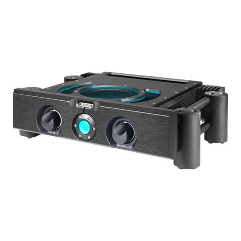
Chord Electronics ULTIMA INTEGRATED User manual

Chord Electronics
Product Communication | English
The Pumphouse, Farleigh Lane, East Farleigh, Kent,
ME16 9NB. Great Britain.
+44 (0) 1622 721 444
info@chordelectronics.co.uk
chordelectronics.co.uk
ULTIMA
INTEGRATED
Manual
-
V1.0

Chord Electronics
ULTIMA INTEGRATED | User manual
2
1 Contents
Introduction 2
Support and warranty 3
Connections and controls 4
Power connection 5
Inputs 6
Connecting to loudspeakers 7
Connecting to a power amp 8
Power on/o 9
Operation 10
12 V trigger 11
Placement 12
Technical specifications 13

Chord Electronics
ULTIMA INTEGRATED | User manual
3
2 Introduction
The ULTIMA INTEGRATED is a highly advanced 125-watt amplifier containing the very latest Chord
Electronics ULTIMA circuit topology.
This manual provides all the information required to set up and operate the device, and further details
can be found online at: chordelectronics.co.uk/ultima-integrated
2.1 Safety and care
•Do not allow the device to come into contact with water or liquids.
•Do not spray cleaning products onto the device. Use a clean microfibre cloth to clean the casework.
•A further safety document is included in the box.
•The device does not contain any user-serviceable components. Do not attempt to open, dismantle or
apply internal third-party devices to it. Doing so will void the warranty.

Chord Electronics
ULTIMA INTEGRATED | User manual
4
3 Support and warranty
For support, please contact the
supplying retailer before contacting
Chord Electronics. Further help can be
found at chordelectronics.co.uk/get-
support
At the point of sale, Chord Electronics Ltd. provides the ULTIMA INTEGRATED with a comprehensive
five-year warranty, which covers defects in materials and workmanship through fair usage.
The warranty is transferable with proof of purchase, however, the warranty on ex-demonstration units
begins from the retailer‘s date of purchase. Warranty claims must be made via the supplying retailer.
For the best possible support and service, please register your purchase with Chord Electronics at:
chordelectronics.co.uk/register-product/

Chord Electronics
ULTIMA INTEGRATED | User manual
5
4 Connections and controls
4.1 Rear and front panels
A
L M N
B C D E F
GH
JK
AA/V bypass XLR inputs BPreamplifier XLR outputs CLine 1 XLR inputs
DLine 2 RCA inputs ELine 3 RCA inputs FLine 4 RCA inputs
G10 A IEC power inlet H12 V trigger connection JLoudspeaker terminals (right) *
KLoudspeaker terminals (left)* LVolume control/input selector
(combined)
MPower button/status sphere
NBalance control/AV bypass
selector (combined)
* Please observe polarities
WARNING: Ensure all system devices are switched o and any volumes are set to zero before making
any connections.

Chord Electronics
ULTIMA INTEGRATED | User manual
6
4.2 Remote control
Note: greyed buttons are not functional on the ULTIMA INTEGRATED
Power button
Balance control
Dim
Input 1 Input 3
2x AAA batteries
(batteries supplied)
Mute
AV bypass select
Volume control +
Volume control -
Input cycle
Input cycle
Input 4 Input 2

Chord Electronics
ULTIMA INTEGRATED | User manual
7
5 Power connection
Connect the amplifier to power using the supplied 10 A power cable. If hum or buzz occurs, try using a
good-quality (earthed) power distribution block

Chord Electronics
ULTIMA INTEGRATED | User manual
8
6 Inputs
Connect the amplifier to balanced source components using XLR input 1, observing R/L connectivity.
Connect the amplifier to unbalanced source components using RCA inputs 2-4, observing R/L (red/
black) connections between the source and the amplifier.
Good-quality cables are recommended. For input selection see ‘Operation’.
6.1 AV bypass
The AV bypass feature allows the output of an AV processor or receiver to directly connect to the
amplifier’s balanced AV input. The amplifier’s volume control and signal processing are eectively
bypassed, so that the signal from the connected AV device reaches the power amplifier section as if
it were connected directly.
This can be useful for watching video where high-quality two-channel audio is desirable.
1) Connect the amplifier’s balanced XLR AV bypass input (A/V) to the corresponding output on the
partnering AV device.
2) Select the appropriate output on the connected AV device and ensure that AV bypass mode has
been selected on the ULTIMA INTEGRATED, by pressing and holding the ‘Balance/AV’ control knob
inwards (click) until purple is shown on the circular light ring. Pressing and holding a second time will
exit AV bypass mode and the circular light ring will return to white.

Chord Electronics
ULTIMA INTEGRATED | User manual
9
7 Connecting to loudspeakers
Connect the amplifier to loudspeakers using good-quality loudspeaker cable, terminated with 4 mm
banana plugs. Observe L and R channel, and black/red polarity is consistent at both the amplifier and
loudspeaker end. If using spade plugs, unscrew the amplifier’s loudspeaker terminals, connect the
spades securely, and re-tighten the terminals. Although bare wire can be used, it is not recommended.
or

Chord Electronics
ULTIMA INTEGRATED | User manual
10
8 Connecting to a power amp
The ULTIMA INTEGRATED can be used as a preamplifier to provide a signal for another power amplifier
if desired.
Connect the XLR PRE OUT ‘R’ to the right input on the corresponding power amplifier, and connect ‘L’
to the left input.
8.1 Bi-amping
The ULTIMA INTEGRATED can be used with an additional power amp to bi-amp compatible speakers.
All Chord Electronics amplifiers are gain-matched, if you wish to use another manufacturer’s power amp,
ensure the gain matches the ULTIMA INTEGRATED.
Before bi-amping, power the system o and ensure the speaker terminal links are removed or damage to
your speakers and amplifiers may occur.
When using an additional power amplifier, connect the XLR PRE OUT ‘R’ to the right input on the
corresponding power amplifier, and connect XLR PRE OUT ‘L’ to the left input. From the ULTIMA
INTEGRATED, run one pair of speaker cables to the high frequency inputs on the speakers (observing
polarity). From any matching power amplifier run a second pair of speaker cables to the low frequency
input on the speakers (observing polarity).
Note: the outputs from the ULTIMA INTEGRATED are always active. If in doubt please consult your
retailer.

Chord Electronics
ULTIMA INTEGRATED | User manual
11
9 Power on/o
With all cable connections successfully made and the volume on the amplifier set to zero, press the
front-panel power sphere to switch the amplifier on. The amplifier will perform a safety check and the
sphere will change colour from red (standby), to green and then cyan (on), ready for use.
In standby mode, the ULTIMA INTEGRATED consumes very little energy (just 1 W) and, therefore, can be
left in this mode at all times, if desired.

Chord Electronics
ULTIMA INTEGRATED | User manual
12
10 Operation
10.1 Input selection
Select between inputs 1-4 by pressing the front-panel volume/IP control inwards sequentially (click).
Input 1: (red)
Input 2: (yellow)
Input 3: (green)
Input 4: (blue)
10.2 Volume control
Volume can be adjusted using the front panel volume/IP control (rotate the knob clockwise/counter-
clockwise).
10.3 Balance
Balance can be adjusted using the front panel balance/AV control (rotate the knob clockwise/counter-
clockwise).
10.4 AV bypass
With all connections made as outlined in the AV bypass section, the AV bypass mode can be selected by
pressing and holding the front panel balance/AV control inwards (click). The light colour will change
from white to purple. Pressing and holding the button a second time will exit AV bypass mode and
return the light to white.
Note: some operations, such as mute and dim (LED), are only accessible via the remote control; see 4.2.

Chord Electronics
ULTIMA INTEGRATED | User manual
13
12 V trigger
Partnering devices with a compatible 12 V trigger input can be connected with a suitable cable for
simultaneous power on/o from standby mode. When connected the front panel button LED will turn
yellow and once triggered the LED will change to purple.

Chord Electronics
ULTIMA INTEGRATED | User manual
14
11 Placement
The amplifier benefits from extensive casework ventilation and heatsinking, however, care should be
taken to ensure the device is used in a well-ventilated setting, away from direct sunlight and heat
sources, with sucient space (at least 10 cm) around the unit.
If stacking the amplifier with other units, it is advisable to place the unit atop others.

Chord Electronics
ULTIMA INTEGRATED | User manual
15
12 Technical Specifications
Please go to our website for the most recent specifications: www.chordelectronics.co.uk
Dimensions with Integra legs 13 cm (H) x 48 cm (W) x 38 cm (D)
Dimensions with side blocks 11 cm (H) x 43 cm (W) x 38 cm (D)
Frequency response 10 Hz-200 kHz +/- 3 dB
THD 0.01 % 20 Hz-20 kHz
Signal-to-noise ratio 90 dB on all inputs
Input impedance 100 kΩ
Input maximum voltage Unbalanced: 3 V RMS Balanced: 6 V RMS
Output maximum voltage 35 V RMS
Gain 21 dB
Channel separation 100 dB
Operation voltage 80-250 V AC auto-switching
Power output 125 W into 8 Ω
Power consumption (Idle/rated o/p) 45 W / 400 W (1 W
standby)

Table of contents
Other Chord Electronics Amplifier manuals
