Christie XENON CONSOLE Owner's manual

DIGITAL SYSTEMS
INSTRUCTIONS
FOR
INSTALLATION AND OPERATION
OF
SLC SERIES
XENON CONSOLE
SLC 20/30,40,45,45R,70
TD-641 REV. 6.0
CHRISTIE DIGITAL SYSTEMS
10550 Camden Drive
Cypress, CA 90630
714-236-8610 Fax: 714-503-3385

Operator’s Manual
Xenon Console, Model SLC 20/30,40,45,45R,70
TD641, Rev. 6.0
Manufactured Under U.S. Patents 3,843,879 and 5,054,909
Other Patents Pending
The information in this document is subject to change without notice and does not represent a
commitment on the part of Christie Digital Systems (hereinafter referred to as Christie).
Christie does not assume responsibility for errors that may appear in this document. Christie
or its subsidiaries, designated representatives, and any other vendor of the SLC Xenon
Console are not responsible in any way for any liabilities or loss resulting from the use or
misuse of this document.
Copyright © 2003 by Christie Digital Systems
All Rights Reserved
All copyrights and trademarks are the property of their respective owners.
CHRISTIE DIGITAL SYSTEMS
10550 Camden Drive
Cypress, CA 90630
Telephone 714-236-8610
FAX 714-503-3385

CHRISTIE DIGITAL SYSTEMS i
August 7, 2003
TABLE OF CONTENTS
TABLE OF CONTENTS..............................................................................i
LIST OF FIGURES AND TABLES..............................................................iii
1. Introduction......................................................................................... 1-1
1.1. Contents of the Manual.................................................................................................. 1-1
1.2. Who Should Use This Manual?..................................................................................... 1-1
1.3. Special Notices .............................................................................................................. 1-2
1.3.1. Warning ..................................................................................................................1-2
1.3.2. Caution ................................................................................................................... 1-2
1.3.3. Note ........................................................................................................................ 1-2
2. Safety Precautions ............................................................................. 2-1
2.1. Wear Protective Clothing ..............................................................................................2-1
2.2. Allow Lamp to Cool ...................................................................................................... 2-2
2.3. Disconnect AC Lines Before Entering Console ............................................................ 2-2
2.4. Do Not Look Directly at Lamp...................................................................................... 2-2
2.5. Avoid Fire Hazards........................................................................................................ 2-3
3. General Description............................................................................ 3-1
3.1. The Xenon Lamp ...........................................................................................................3-1
4. Installation Procedures ...................................................................... 4-1
4.1. Unpacking...................................................................................................................... 4-1
4.2. Installation ..................................................................................................................... 4-1
4.2.1. Leveling Feet .......................................................................................................... 4-1
4.2.2. Door Panels ............................................................................................................ 4-4
4.2.3. Venting ................................................................................................................... 4-4
4.2.4. Mounting the Projector........................................................................................... 4-5
4.3. Electrical Connections ................................................................................................... 4-5
4.3.1. Verify Voltage ........................................................................................................ 4-5
4.3.2. Wiring Hook-Up.....................................................................................................4-5
5. Alignment and Checkout Procedures............................................... 5-1
5.1. Mechanical Alignment................................................................................................... 5-1
5.2. Installation of Xenon Lamp ........................................................................................... 5-1
6. Operating the SLC .............................................................................. 6-1
6.1. Safety Review................................................................................................................ 6-1
6.2. Starting and Operating the SLC..................................................................................... 6-1
6.3. Optical Alignment and Adjustment...............................................................................6-4
6.4. Tilt Adjustment.............................................................................................................. 6-5
6.5. Replacing the Lamp ....................................................................................................... 6-5

SLC Series Xenon Console
ii CHRISTIE DIGITAL SYSTEMS
August 7, 2003
6.5.1. Removing the Lamp............................................................................................... 6-5
6.5.2. Installing a New Lamp........................................................................................... 6-5
6.5.3. Defective Lamps .................................................................................................... 6-5
7. Maintenance and Adjustments .......................................................... 7-1
7.1. Before Opening the Console ......................................................................................... 7-1
7.2. Cleaning Optical Surfaces............................................................................................. 7-1
7.2.1. Cleaning Dust......................................................................................................... 7-2
7.2.2. Cleaning Grease ..................................................................................................... 7-2
7.3. Maintaining Other Surfaces .......................................................................................... 7-2
7.3.1. Blower.................................................................................................................... 7-3
7.3.2. Igniter ..................................................................................................................... 7-3
7.3.3. Air Flow Interlocks ................................................................................................ 7-3
7.4. Aligning Lamphouse Without Alignment Tools........................................................... 7-3
7.5. Xenon Lamp Autofocus Adjustments (Option ABF) ................................................... 7-4
7.5.1. Autofocus Adjustment Procedures......................................................................... 7-4
7.6. Optimizer Reflector....................................................................................................... 7-6
7.7. Electrical Connections................................................................................................... 7-6
7.8. Airflow .......................................................................................................................... 7-6
7.9. Remote Lamp Adjustment Control (Option RBA) ....................................................... 7-6
8. Troubleshooting.................................................................................. 8-1
8.1. Malfunction: Power Supply Does Not Start.................................................................. 8-1
8.2. Malfunction: Lamp Does Not Ignite ............................................................................. 8-2
8.3. Power Supply Output Is Low Or Not Steady................................................................ 8-2
WARRANTY............................................................................................W-1
Appendix A: Assembly Diagrams and Parts Lists.............................. A-1

Table of Contents
CHRISTIE DIGITAL SYSTEMS iii
August 7, 2003
iii
LIST OF FIGURES AND TABLES
Figure 2-1: Protective Clothing Safety Kit Contents..............................................................2-1
Figure 4-1: SLC Xenon Lamp Console (Front View) ............................................................ 4-2
Figure 4-2: SLC Xenon Lamp Console (Rear View) ............................................................. 4-3
Figure 4-3: Minimum and Maximum Exhaust Airflow Requirements for SLC Consoles..... 4-4
Figure 4-4: Minimum Wire Sizes for AC Connections .......................................................... 4-6
Figure 4-5: Minimum Wire Sizes for DC Connections .......................................................... 4-6
Figure 5-1: Plenum, Top View ............................................................................................... 5-2
Figure 6-1: Control Panel........................................................................................................ 6-2
Figure 6-2: Optical Alignment of Xenon Lamp......................................................................6-4
Table 8-1: Troubleshooting for Power Supply Does Not Start ............................................. 8-1
Table 8-2: Troubleshooting for Lamp Does Not Ignite.........................................................8-2
Table 8-3: Troubleshooting for Power Supply Output Low or Not Steady ..........................8-2
Figure A-1: Autofocus Assembly ........................................................................................... A-2
Table A-1: Parts List for Autofocus Assembly ..................................................................... A-3
Figure A-2: SLC Xenon Lamp Console (Front View) ........................................................... A-4
Table A-2: Parts List for SLC Xenon Lamp Console (Front View) ..................................... A-5
Figure A-3: SLC Xenon Lamp Console (Rear View) ............................................................ A-6
Table A-3: Parts List for SLC Xenon Lamp Console (Rear View) ...................................... A-7
Figure A-4: Control Panel.......................................................................................................A-8
Table A-4: Parts List for Control Panel................................................................................. A-9
Figure A-5: Manual Lamp Adjustment Assembly................................................................ A-10
Table A-5: Parts List for Manual Lamp Adjustment Assembly.......................................... A-11
Table A- 6: Parts List for Plenum, All Models (Top View)................................................. A-13
Figure A-7: Power Supply .................................................................................................... A-14
Table A-7: Power Supply .................................................................................................... A-15


1
CHRISTIE DIGITAL SYSTEMS 1-1
August 7, 2003
1. INTRODUCTION
1.1. CONTENTS OF THE MANUAL
This manual contains installation, operation, and operator maintenance procedures for
Christie SLC Xenon Console. The material covered includes:
• General description
• Installation and assembly
• Alignment and checkout procedures
• Operating the SLC
• Troubleshooting.
1.2. WHO SHOULD USE THIS MANUAL?
This manual provides information suitable for various purposes.
All users should read Section 2: Safety Precautions.
WARNING
Do not install, operate, maintain, or repair the SLC Xenon Lamp
Console unless you have read Section 2, are familiar with the safety
precautions, and have followed all warnings and instructions.
For details on operating the projector and for general information, see:
• Section 3: General Description
• Section 4: Installation Procedures
• Section 5: Alignment and Checkout Procedures
• Section 6: Operating the SLC.
Before performing adjustments and periodic maintenance during normal operation, see:
• Section 4: Installation Procedures
• Section 5: Alignment and Checkout Procedures
• Section 7: Maintenance and Adjustments
• Section 8: Troubleshooting.
If a problem occurs, see:
• Section 8: Troubleshooting.
Additional reference information is contained in the appendices.

SLC Series Xenon Console
1-2 CHRISTIE DIGITAL SYSTEMS
August 7, 2003
1.3. SPECIAL NOTICES
Three kinds of specific notices are used within this manual to emphasize specific
information.
1.3.1. WARNING
WARNING
WARNING: Indicates the presence of a hazard that can cause personal
injury if the hazard is not avoided.
1.3.2. CAUTION
CAUTION: Indicates the presence of a hazard that could cause damage
to the system.
1.3.3. NOTE
NOTE: Provides additional information.
2
CHRISTIE DIGITAL SYSTEMS 2-1
August 7, 2003
2. SAFETY PRECAUTIONS
This section highlights the major dangers of working with the SLC Xenon Console.
Appropriate safety measures must be taken at all times.
2.1. WEAR PROTECTIVE CLOTHING
WARNING
POSSIBLE EXPLOSION HAZARD!
Xenon compact arc lamps are under high pressure. The lamps must be handled with great
care. They may explode if dropped or mishandled. Whenever the protective cover is
removed from the lamp, authorized protective clothing must be worn!
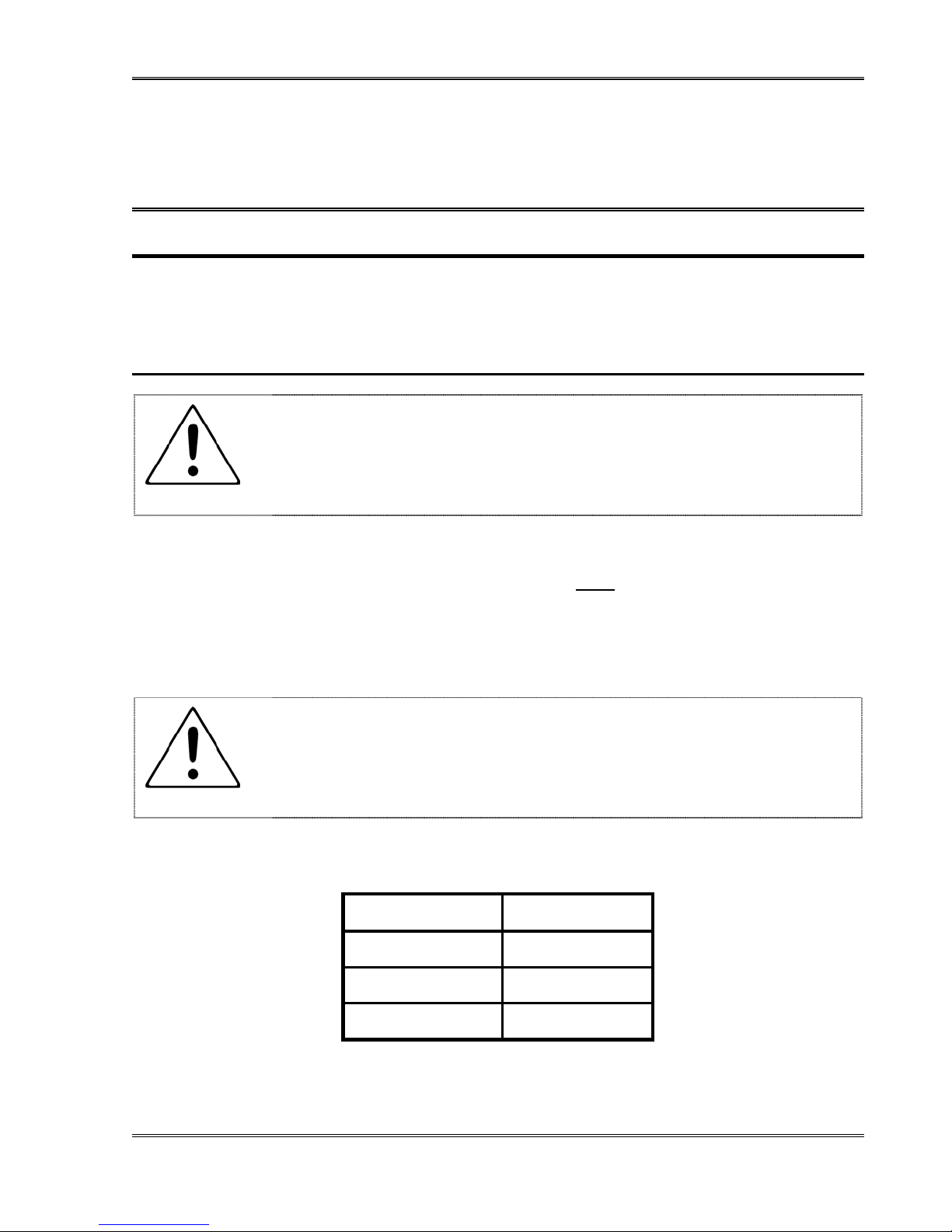
Protective clothing includes, but may not be limited to, rubberized cotton gloves, double-
layer 0.040-inch acetate face shield, and quilted ballistic nylon jacket. A Protective Clothing
Safety Kit (Part Number 598900-095) is available from Christie. Figure 2-1 lists the contents
of the Safety Kit.
WARNING
Wear protective clothing when protective cover is removed from lamp.
Instructions from Christie regarding protective clothing are subject to change. Any local or
federal specifications take precedence.
Part Number Item
598900-092 Safety Jacket
598900-093 Safety Mask
598900-094 Safety Gloves
Figure 2-1: Protective Clothing Safety Kit Contents

SLC Series Xenon Console
2-2 CHRISTIE DIGITAL SYSTEMS
August 7, 2003
2.2. ALLOW LAMP TO COOL
WARNING
If the lamp has been in use, wait at least ten minutes after shut-off
before opening the lamp housing.
The ten-minute waiting period allows the internal lamp pressure to drop to a level at which it
is safe to work while wearing the authorized protective clothing. Again, always wear
protective clothing when the protective cover is removed from the lamp.
2.3. DISCONNECT AC LINES BEFORE ENTERING CONSOLE
WARNING
Turn off the breaker at the building AC power distribution panel before
entering the console.
Always turn off and disconnect power lines before entering the console. This protects
against accidental electrical shock.
2.4. DO NOT LOOK DIRECTLY AT LAMP
WARNING
NEVER LOOK DIRECTLY AT THE LAMP!
Serious and permanent eye damage can be caused by the ultraviolet radiation of the lamp.
Never attempt to open the console while the lamp is on. Always follow directions for
opening console and exposing the Xenon lamp. (See Section 5.2.)
This manual suits for next models
6
Table of contents


