CiA ERMES User manual
ITALIANO
ENGLISH
USER`S MANUAL
GSM phone dialer
with vocal messages

Contents
Chapter 1 Introduction 3
1.1 Operating Features ...........................................................................................3
1.2 Technical Features ............................................................................................3
Chapter 2 Installation 4
2.1 TDC22 connection ............................................................................................4
2.2 ....................................5
2.3 Connection GSM antenna ............6
2.4 Connection GSM net.........................................................................................7
Chapter 3 Programming Procedures 8
3.1 Access to Setup ................................................................................................8
3.1.1 Setup: Voice directory............................................................................9
3.1.2 Setup: Sms directory ...........................................................................10
3.1.3 Setup: Vocal messages........................................................................11
3.1.4 Setup: Sms messages.........................................................................13
3.1.5 Setup: Channels ..................................................................................14
3.1.6 Setup: Outputs.....................................................................................16
3.1.7 Setup: Parameters...............................................................................18
3.1.8 Setup: Codes .......................................................................................20
3.1.9 Setup: CLIP .........................................................................................21
3.1.10 Setup: Info ...........................................................................................23
Chapter 4 Operation 24
4.1 Operation general description .........................................................................24
4.2 Local control....................................................................................................24
4.2.1 Local control: CYCLES STOP .............................................................25
4.2.2 Local control: CALLING STOP ............................................................25
4.2.3 Local control: OUTPUTS CONTROL...................................................26
4.2.4 Local control: INPUTS CONDITION ....................................................27
4.2.5 Local control: OUTPUTS CONDITION ................................................27
4.2.6 Local control: OUT OF ORDER...........................................................28
4.2.7 Local control: IN OF ORDER...............................................................28
4.2.8 Local control: CALL .............................................................................29
4.3 Remote control.................................................................................................30
4.4 CLIP function...................................................................................................31
TDC30 / ERMES / TM20GSM / TM60GSM connection
TDC30 / ERMES / TM20GSM / TM60GSM
2 3
1 Introduction
1.1 Operating Features
!
!
!
!
!
!
!
!
!
!
!
!
!
!
!
!
Incorpreted GSM module.
Indication intensity of GSM net.
6 (in ERMES / TM60GSM) or 2 (in TDC30 / TDC22 / TM20GSM) inputs of activation alarm,
everyone with vocal message of 16 seconds and a SMS of 100 characters forwarding
towards fixed telephone or mobiles.
2 outputs with (plus 4 to opened collector, only in ) controlling by
telephone by DTMF, or by a single ring (missed call) from one of the present telephone in
directory, with relative re-sending of a confirmation ring ( CLIP function).
Vocal directory of16 numbers, and SMS directory of other 16 numbers.
Listening ambient from remote with voice lives function.
Delays on the programming inputs singularly.
Possibility to link together every telephone number to all or to some channel. Number of
repetition message and cycles of programming call.
Call masking ID.
Tamper anti opening.
Container inABS with lodging for battery 12 V 7Ah.
Incorporated storage power source only in ).
2 codes operator to program ( MASTER code and CONTROLS code).
relè ERMES / TM60GSM
Monitoring of the condition of inputs and outputs from remote trough short vocal messages
(of 2 sec.), and from local trough short SMS messages (of 16 car.) on display all
personality for every channel and on its key.
Inputs programming in way impulse or state, conditioned to the logical input “INT”.
Outputs programming in way impulse or state, conditioned to inputs.
( ERMES/TM60GSM
1.2 Technical Features
!Operating voltage: 13 Vcc ±5%
!Absorption: < 100 mAin St/by; 400 mA max
!Inputs: 6 (in ERMES / TM60GSM) or 2 (in TDC30 / TDC22 / TM20GSM) + 1 “INT” of
condition
!Outputs relè to exchange: 2
!Outputs to opened collector: 4 (in ERMES / TM60GSM); 1 (in TDC22).
!Vocal messages: 6 (in ERMES / TM60GSM) or 2 (in TDC30 / TDC22 / TM20GSM) of 15
sec., one for every channel; 26 (in ERMES / TM60GSM) or 10 (in TDC30 / TDC22 /
TM20GSM) of 2 sec., for the condition of every inputs and outputs, in whichever
conditions.
!SMS messages: 6 (in ERMES / TM60GSM) or 2 (in TDC30 / TDC22 / TM20GSM) of 100
car., one for every channel; 26 (in ERMES / TM60GSM) or 10 (in TDC30 / TDC22 /
TM20GSM) of 16 car., For the condition of every inputs and outputs, in whichever
conditions.
!Voice directory: 16 number
!SMS directory: 16 other numbers
IntroductionERMES - TM60GSM - TDC30 - TDC22 - TM20GSM - User manual
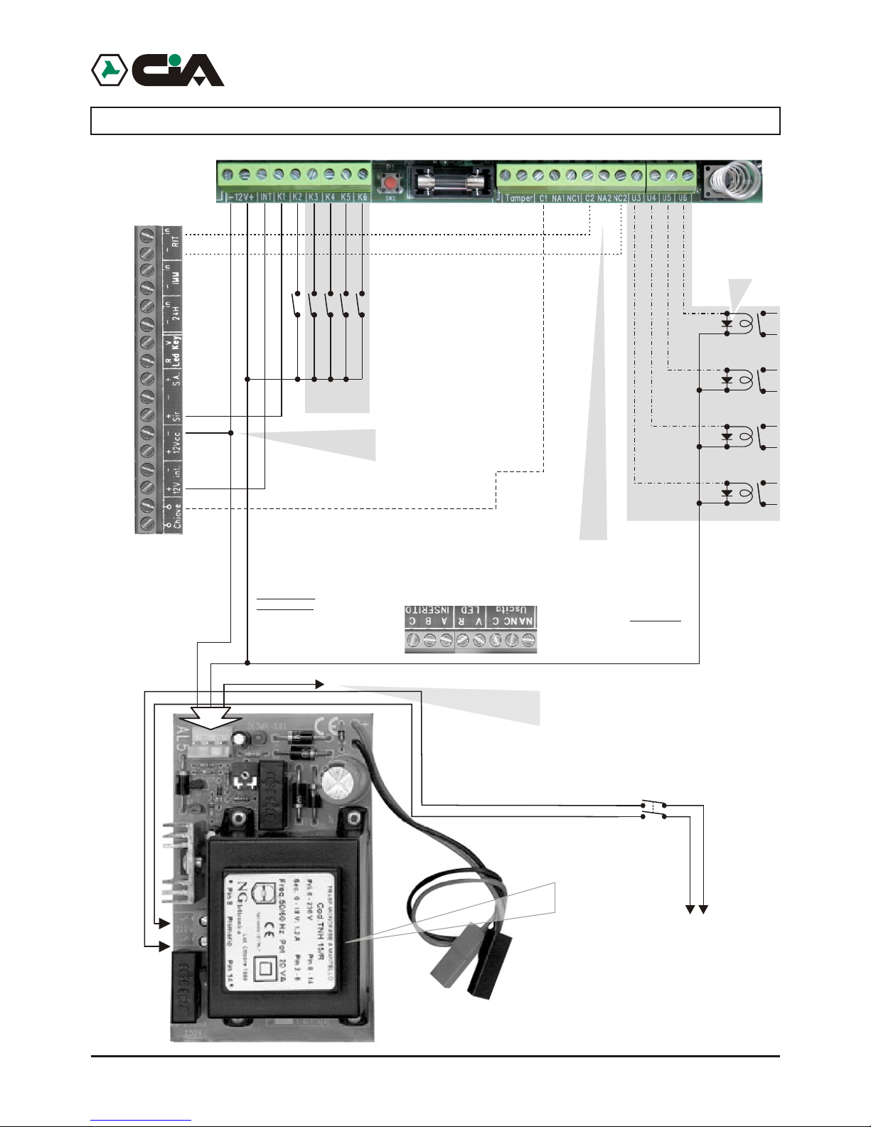
2.2 TDC30 / ERMES / TM20GSM / TM60GSM connection
4 5
Installation
Burglar
central unit
IN2
IN3
IN4
IN5
IN6
IN1
This connection
at a distance allows
the exclusion of a zone of
burglar central unit
OUT3
OUT4
OUT5
OUT6
This connection allows
the insertion and the not insertion
at a distance of burglar central unit
united to uses of electronic
key.
Be careful!
In order to use the
positive outputs ‘+ Sir’ e ‘+ Int.’
Of burglar central the negative
must be in common
to the feeding of
ERMES
If only present
positive ‘+Int.’ the output alarm
‘+Sir.’connected on input 1
will be operating
(see Programming)
This connection, if used, consents
to send to one of inputs (K1,K2...) A positive one
of reference in presence of main voltage 230 Vac.
Setting up in the programming the input like
“Positive Level”, to lacking the mains voltage
telephone dialer will send the message of relative alarm.
Electronic
key
INT
+ Sir.
+ Int.
Similar
1N4004 or
Diode valves
only in
ERMES / TM60GSM
only in
ERMES / TM60GSM
Net
230V~
50Hz
Sezionatore
only in
ERMES / TM60GSM
2 Installation
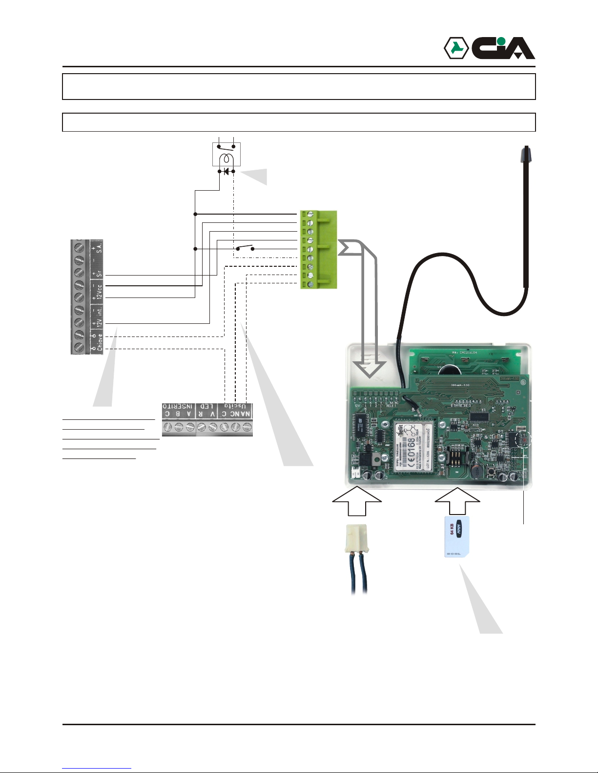
2.1 TDC22 connection
4
+K2
+K1
This connection allows the input and output
of the burglar alarm whether with the electronic key as with phone dial.
NOTE: If you use only the phone dial is necessary
to connect only the output C and
NC of the Relè1 of the phone dial on Key terminals of the exchange.
Just if the positive '+Int.'
is present , the alarm
output '+Sir.' linked on the
input 1, will be operative.
(See programming)
Electronic
key
+INT
+ Sir.
+ Int.
Diode
1N4004 or
similar
+12V
-12V
2 relay (optional)
-OUT2
C OUT1
NA OUT1
NC OUT1
TDC22
1. Through the use of any GSM phone is necessary to eliminate
the access code (code PIN) that qualifies the Sim card use.
2. Insert Sim Card in the module according to the rounded corner.
Tamper 24h
RESET
BURGLARY
CENTRAL UNIT
OUT1
OUT2
ERMES / TM60GSM / TDC30 / TDC22 / TM20GSM
ERMES - TM60GSM - TDC30 - TDC22 - TM20GSM - User manual
2.2 TDC30 / ERMES / TM20GSM / TM60GSM connection
4 5
Installation
Burglar
central unit
IN2
IN3
IN4
IN5
IN6
IN1
This connection
at a distance allows
the exclusion of a zone of
burglar central unit
OUT3
OUT4
OUT5
OUT6
This connection allows
the insertion and the not insertion
at a distance of burglar central unit
united to uses of electronic
key.
Be careful!
In order to use the
positive outputs ‘+ Sir’ e ‘+ Int.’
Of burglar central the negative
must be in common
to the feeding of
ERMES
If only present
positive ‘+Int.’ the output alarm
‘+Sir.’connected on input 1
will be operating
(see Programming)
This connection, if used, consents
to send to one of inputs (K1,K2...) A positive one
of reference in presence of main voltage 230 Vac.
Setting up in the programming the input like
“Positive Level”, to lacking the mains voltage
telephone dialer will send the message of relative alarm.
Electronic
key
INT
+ Sir.
+ Int.
Similar
1N4004 or
Diode valves
only in
ERMES / TM60GSM
only in
ERMES / TM60GSM
Net
230V~
50Hz
Sezionatore
only in
ERMES / TM60GSM
2 Installation
2.1 TDC22 connection
4
+K2
+K1
This connection allows the input and output
of the burglar alarm whether with the electronic key as with phone dial.
NOTE: If you use only the phone dial is necessary
to connect only the output C and
NC of the Relè1 of the phone dial on Key terminals of the exchange.
Just if the positive '+Int.'
is present , the alarm
output '+Sir.' linked on the
input 1, will be operative.
(See programming)
Electronic
key
+INT
+ Sir.
+ Int.
Diode
1N4004 or
similar
+12V
-12V
2 relay (optional)
-OUT2
C OUT1
NA OUT1
NC OUT1
TDC22
1. Through the use of any GSM phone is necessary to eliminate
the access code (code PIN) that qualifies the Sim card use.
2. Insert Sim Card in the module according to the rounded corner.
Tamper 24h
RESET
BURGLARY
CENTRAL UNIT
OUT1
OUT2
ERMES / TM60GSM / TDC30 / TDC22 / TM20GSM
ERMES - TM60GSM - TDC30 - TDC22 - TM20GSM - User manual
6 7
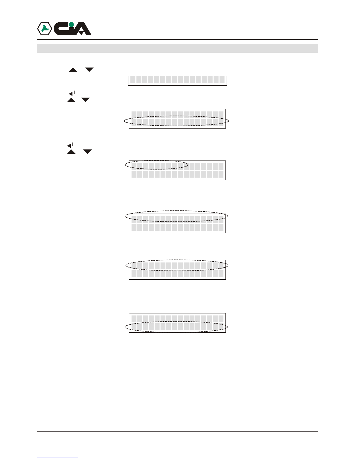
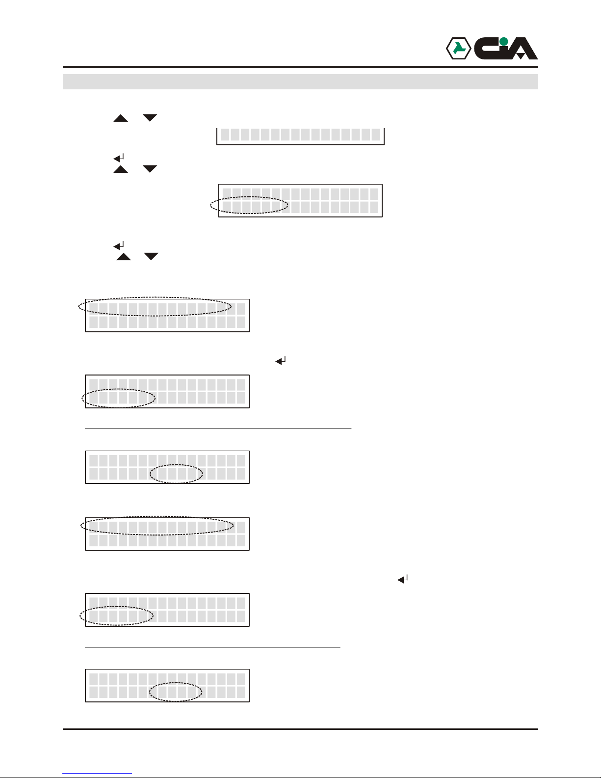
2.4 Connection GSM net
At the starting of mobile telephone dialer, or in case of reset, it starts the search of GSM
net and display visualizes following messages:
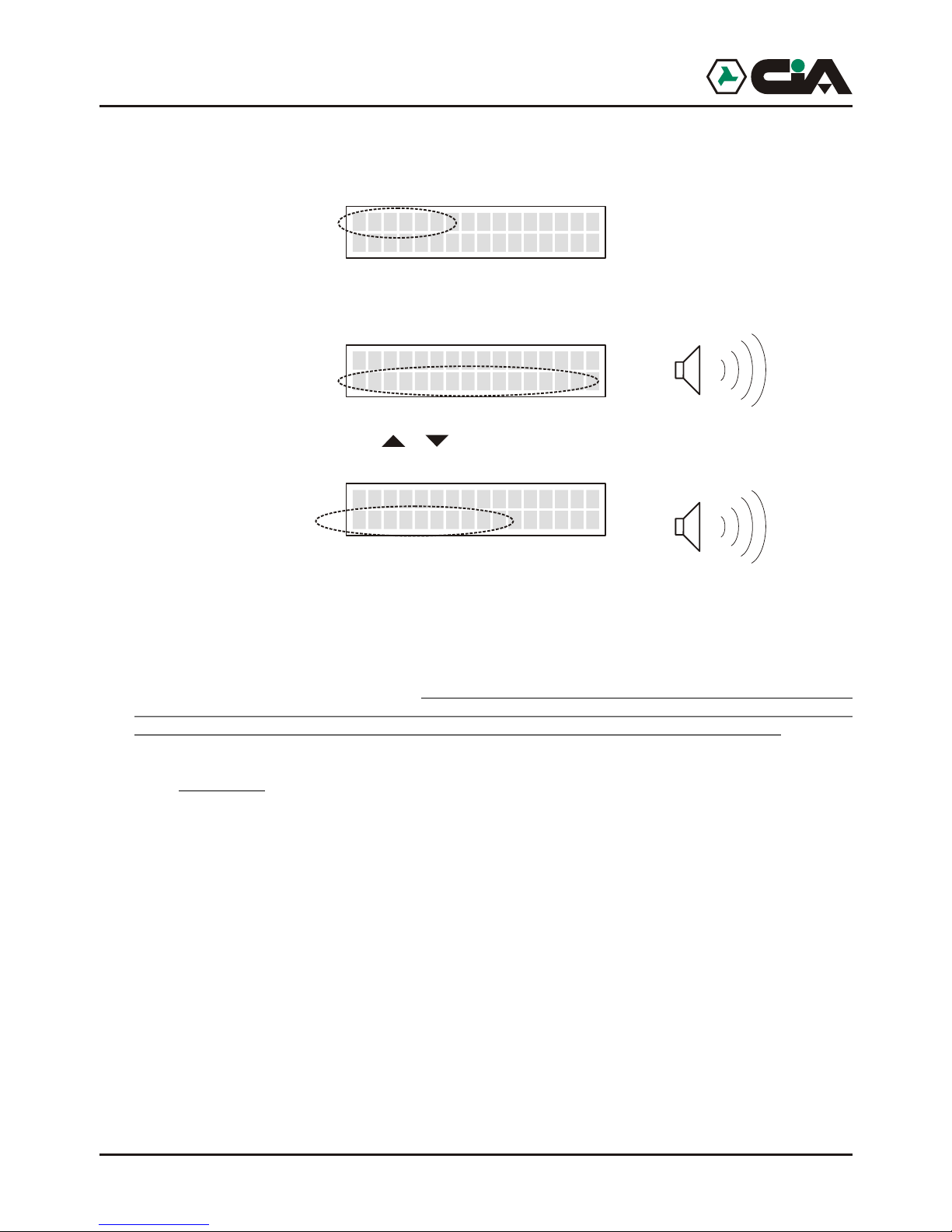
At the end of searching, if mobile telephone dialer is connected to the GSM net will be
visualized the state of recording like continuation:
Low intensity of band
Optimal intensity of band
or, if not connected:
Absent intensity of band
Recording not happened
Denied recording
It is possible to orient the antenna connected to GSM module and to fix with biadhesive
already present on its back in order to consent a greater reception.
BE CAREFUL: in mobile telephone dialer is recorded code IMEI of GSM module,
and for this reason the two devices never go replaced or used separately: replacing
GSM module mobile telephone dialer stops to work .
LED “On” present on the panel indicates the activity of GSM module; LED “State”,
instead, it indicates the control that mobile telephone dialer carries out on GSM module:
!flashing: normal operation
!fast flashing: during a connection
!Fixed(startedor extinguished): in inactivity or error condition
> I TIM_____ _
>>>>> I TIM__
> Not signal_____ _
>>>>> Not Reg.__
>>>>> Denied Reg__
Installation
______Find
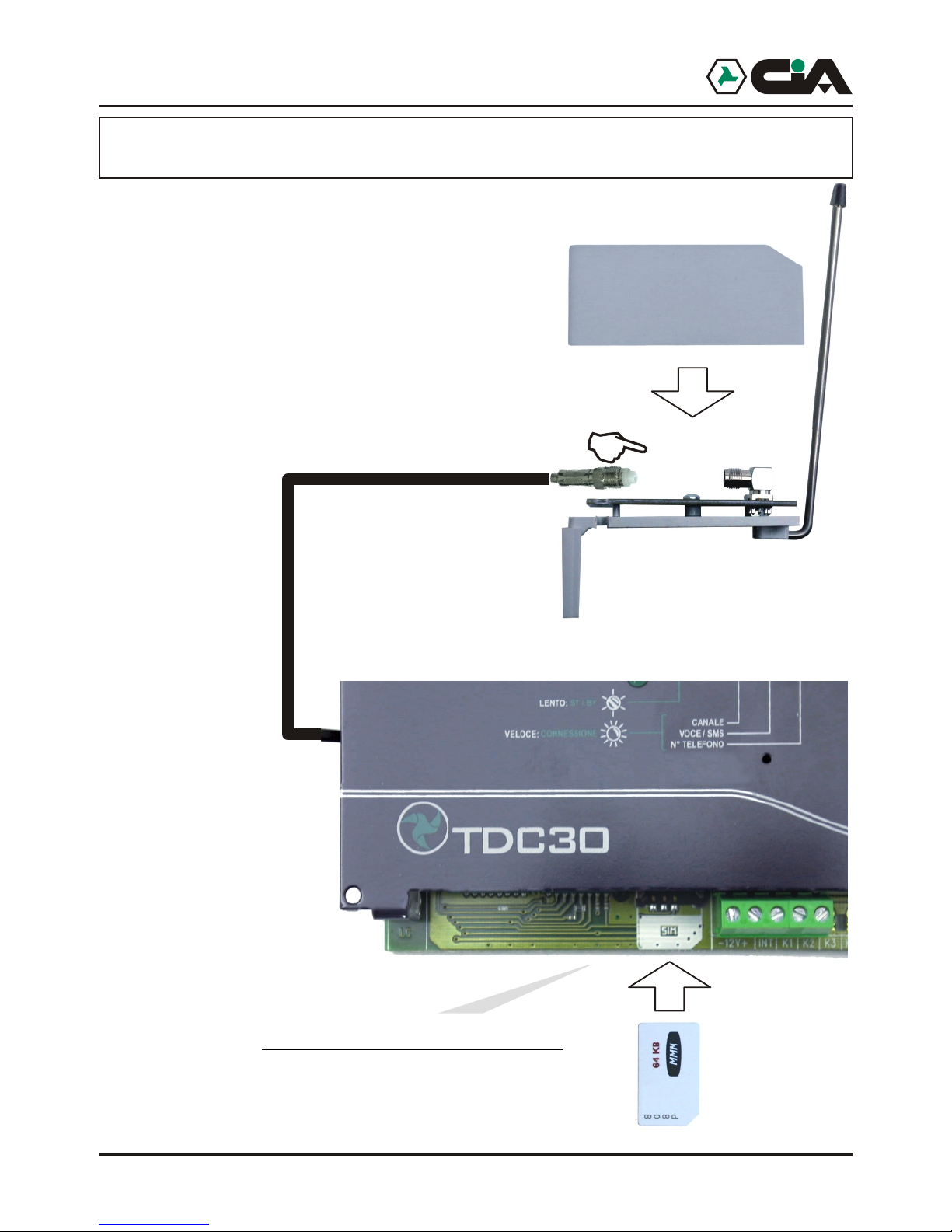
1.By the used of a whichever GSM telephone is necessary
to eliminate the access code ( PIN code)
that qualifies the used SIM card;
2.Entering SIM card to the inside of module
being held account of the dulled angle:
2.3 Connection antenna GSM (ERMES - TM60GSM - TDC30 -
TM20GSM)
Before feeding mobile telephone dialer to make sure itself to have connected
antenna GSM like in figure:
ERMES - TM60GSM - TDC30 - TDC22 - TM20GSM - User manual
6 7
2.4 Connection GSM net
At the starting of mobile telephone dialer, or in case of reset, it starts the search of GSM
net and display visualizes following messages:
At the end of searching, if mobile telephone dialer is connected to the GSM net will be
visualized the state of recording like continuation:
Low intensity of band
Optimal intensity of band
or, if not connected:
Absent intensity of band
Recording not happened
Denied recording
It is possible to orient the antenna connected to GSM module and to fix with biadhesive
already present on its back in order to consent a greater reception.
BE CAREFUL: in mobile telephone dialer is recorded code IMEI of GSM module,
and for this reason the two devices never go replaced or used separately: replacing
GSM module mobile telephone dialer stops to work .
LED “On” present on the panel indicates the activity of GSM module; LED “State”,
instead, it indicates the control that mobile telephone dialer carries out on GSM module:
!flashing: normal operation
!fast flashing: during a connection
!Fixed(startedor extinguished): in inactivity or error condition
> I TIM_____ _
>>>>> I TIM__
> Not signal_____ _
>>>>> Not Reg.__
>>>>> Denied Reg__
Installation
______Find
1.By the used of a whichever GSM telephone is necessary
to eliminate the access code ( PIN code)
that qualifies the used SIM card;
2.Entering SIM card to the inside of module
being held account of the dulled angle:
2.3 Connection antenna GSM (ERMES - TM60GSM - TDC30 -
TM20GSM)
Before feeding mobile telephone dialer to make sure itself to have connected
antenna GSM like in figure:
ERMES - TM60GSM - TDC30 - TDC22 - TM20GSM - User manual
8
3 Programing procedures
3.1 Access to programming
To work, mobile telephone dialer needs at least a telephone number in vocal Directory or in
SMS Directory , and moreover it is necessary that at least it is recorded a Vocal Message or a
SMS Message.
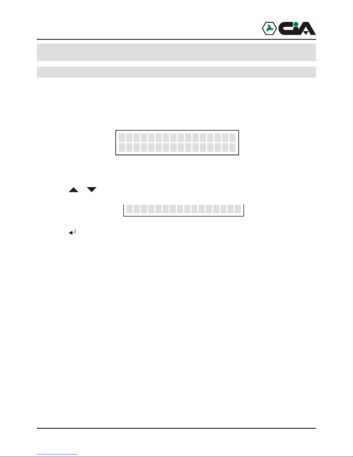
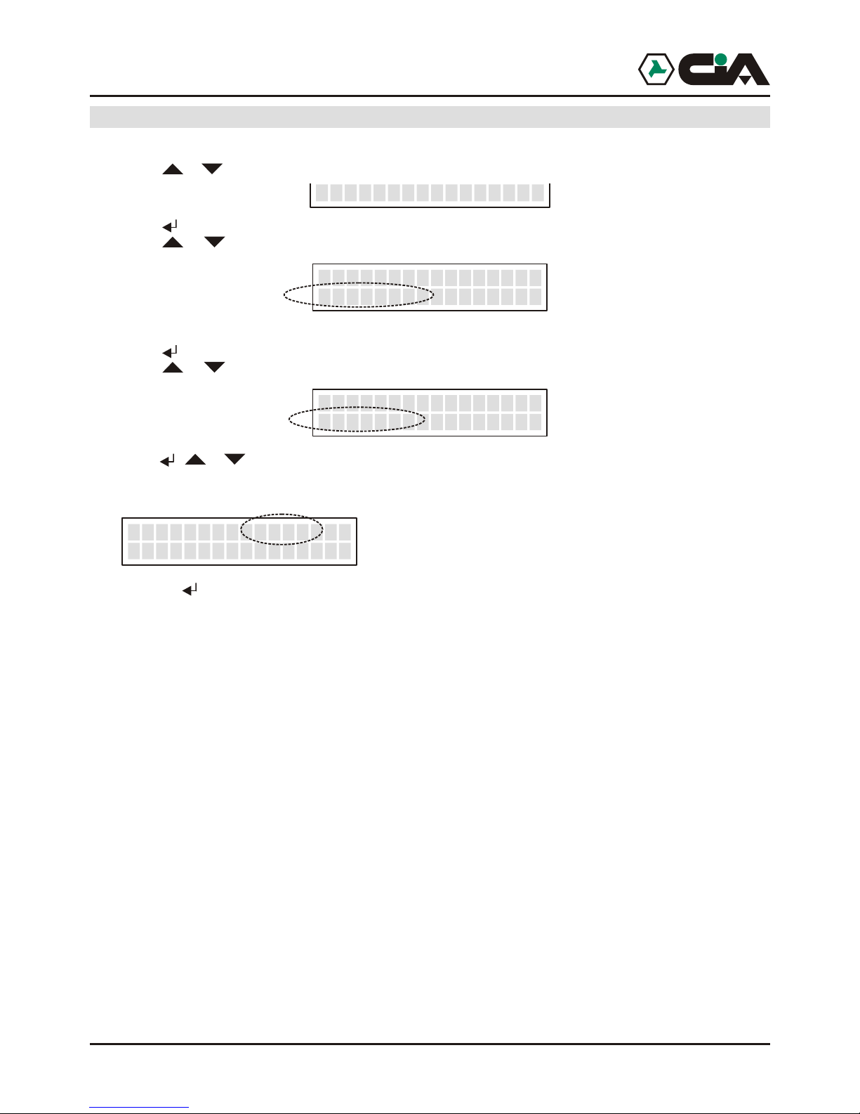
In st/by condition mobile telephone dialer visualizes name of operating of GSM, and, spin
,the condition of 6 (or 2,in TDC30) channels of inputs:
To enter to menu:
1. Press MASTER code (default “1234”);
2. Press o r until visualizing:
3. Press (to enter directly in programming, to point 2 press “8”).
The programming of mobile telephone dialer previews:
!Vocal Directory 16 telephone numbers to which it will be forward Vocal Messages
!SMS Directory 16 telephone numbers to which it will be forward SMS Messages, and from
which commandos CLIP will be activated
!Vocal Messages 6 (in ERMES / TM60GSM) or 2 (in TDC30 / TDC22 / TM20GSM) vocal
messages of 15 seconds relative to activations of channels
2 vocal messages of 2 seconds relative to two conditions of input INT
12 (in ERMES / TM60GSM) or 4 (in TDC30 / TDC22 / TM20GSM) vocal
messages of 2 seconds relative to two conditions of every inputs
12 (in ERMES / TM60GSM) or 4 (inTDC30 / TDC22 / TM20GSM) vocal
messages of 2 seconds relative to two conditions of every outputs
!SMS Messages 6 (in ERMES / TM60GSM) or 2 (in TDC30 / TDC22 / TM20GSM) SMS of 100
characters relative to activations of channels 2 SMS of16 characters relative
to two conditions of input INT 12 (in ERMES / TM60GSM) or 4 (in TDC30 /
TDC22 / TM20GSM) SMS of 16 characters relative to two states of every
inputs 12 (in ERMES / TM60GSM) or 4 (in TDC30 / TDC22 / TM20GSM) SMS
of 16 characters relative to two states of every outputs.
!Channels Set up inputs, of conditions and of activation delays
!Outputs Set up outputs
!Parameters Amount cycles, amount messages, masking ID, automatic answer
!Codici Variation of MASTER code and of Controls Code
!CLIP Activation of outputs by rings from the present telephones in SMS Directory
!Info Visualization informations of firmware.
!
>>>>> I TIM
----- C1 Ready
__
__
8-PROGRAMMING
9
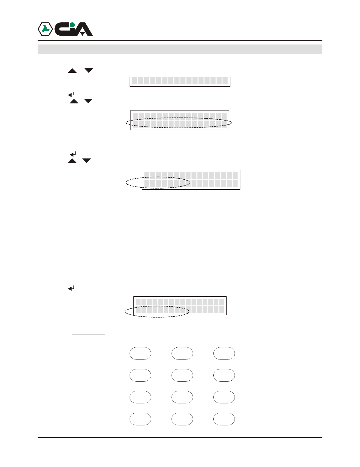
3.1.1Programming: Voice Directory
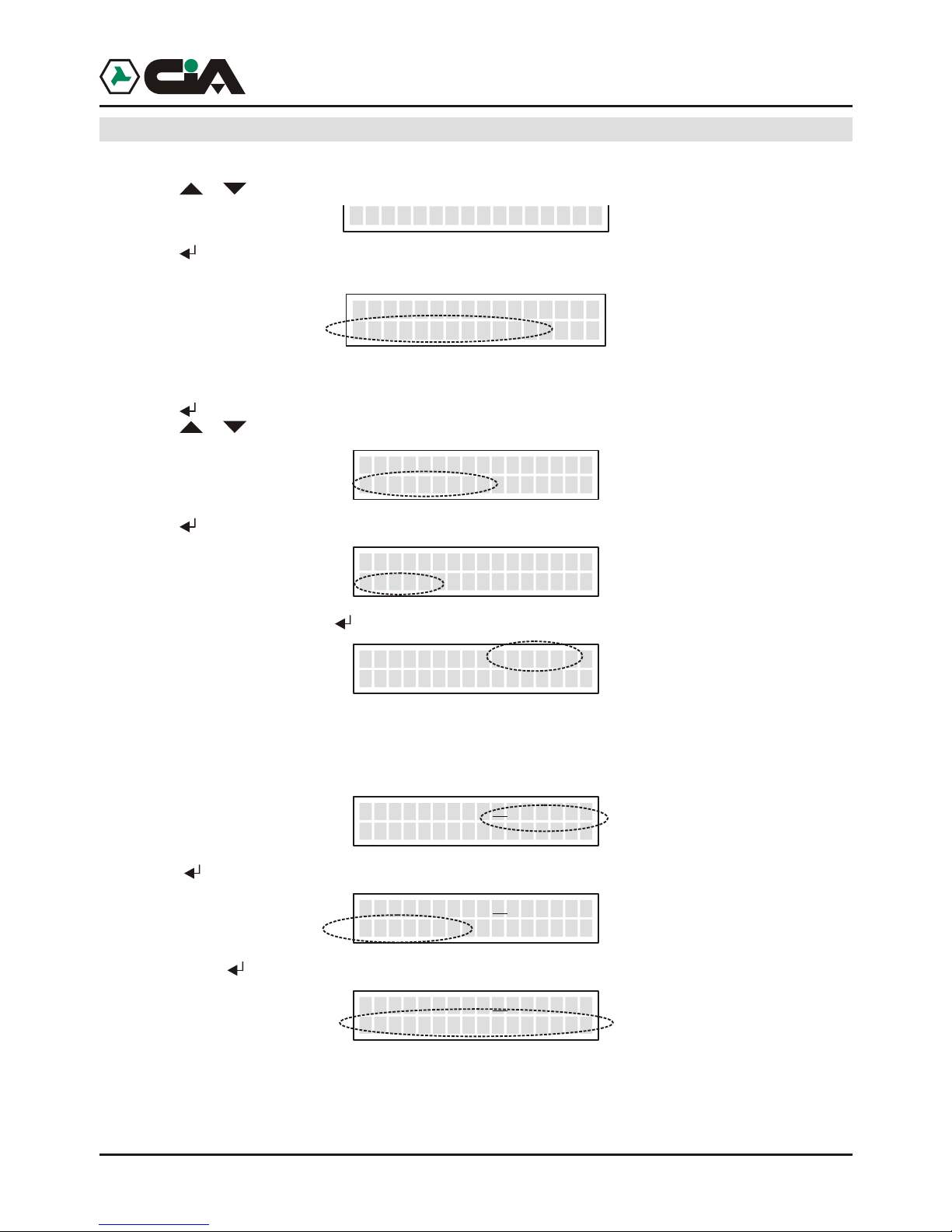
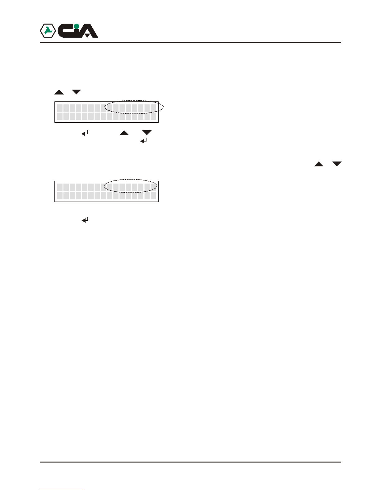
1. Enter to main menu pressing MASTER Code (default “1234”);
2. Press or until visualizing:
3. Press (or, to enter directly in programming “8” after Code);
4. Visualize:
Here it is possible to add cellular telephone numbers or of fixed net to which they will be send 6Vocal
Messages of alarm
5. Press to enter;
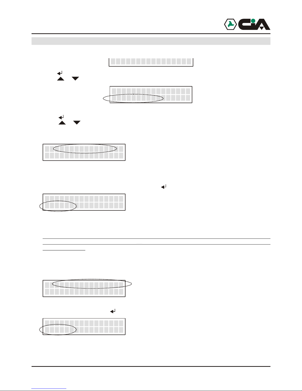
6. Press or to N. Voice to program:
7. Press to insert the number :
8. Insert the number, so press for assignation of the numbers of the channels:
9. Pressing from “1” to “6” it will be possible to assign telephone number admitted to the channels that
will be visualize: for example, press“1”, “4”, “6” to qualify the channels 1, 4 and 6 to send, when they
are activated, the message of alarm to this telephone number; to eliminate the allocation it is enough
newly press the number of the channels:
10. Press :
11. Confirm with :
In this way, if channel 1 or 4 or 6 only comes alarmed the call to this number will be forward and send
the relative message of alarm.
To insert other numbers repeat operations from point 6.
8-PROGRAMMING
__
>PROGRAMMING<
Phonebook Voice
Voice 01>------
<Empty>
_
Voice 01>------
_
_
Voice 01>------
3336667788
_
Voice 01>1--4-6
3336667788
_
Voice 01>1--4-6
Save
_
Voice 01>1--4-6
>> COMPLETED <<
_
__
ProgrammingERMES - TM60GSM - TDC30 - TDC22 - TM20GSM - User manual
8
3 Programing procedures
3.1 Access to programming
To work, mobile telephone dialer needs at least a telephone number in vocal Directory or in
SMS Directory , and moreover it is necessary that at least it is recorded a Vocal Message or a
SMS Message.
In st/by condition mobile telephone dialer visualizes name of operating of GSM, and, spin
,the condition of 6 (or 2,in TDC30) channels of inputs:
To enter to menu:
1. Press MASTER code (default “1234”);
2. Press o r until visualizing:
3. Press (to enter directly in programming, to point 2 press “8”).
The programming of mobile telephone dialer previews:
!Vocal Directory 16 telephone numbers to which it will be forward Vocal Messages
!SMS Directory 16 telephone numbers to which it will be forward SMS Messages, and from
which commandos CLIP will be activated
!Vocal Messages 6 (in ERMES / TM60GSM) or 2 (in TDC30 / TDC22 / TM20GSM) vocal
messages of 15 seconds relative to activations of channels
2 vocal messages of 2 seconds relative to two conditions of input INT
12 (in ERMES / TM60GSM) or 4 (in TDC30 / TDC22 / TM20GSM) vocal
messages of 2 seconds relative to two conditions of every inputs
12 (in ERMES / TM60GSM) or 4 (inTDC30 / TDC22 / TM20GSM) vocal
messages of 2 seconds relative to two conditions of every outputs
!SMS Messages 6 (in ERMES / TM60GSM) or 2 (in TDC30 / TDC22 / TM20GSM) SMS of 100
characters relative to activations of channels 2 SMS of16 characters relative
to two conditions of input INT 12 (in ERMES / TM60GSM) or 4 (in TDC30 /
TDC22 / TM20GSM) SMS of 16 characters relative to two states of every
inputs 12 (in ERMES / TM60GSM) or 4 (in TDC30 / TDC22 / TM20GSM) SMS
of 16 characters relative to two states of every outputs.
!Channels Set up inputs, of conditions and of activation delays
!Outputs Set up outputs
!Parameters Amount cycles, amount messages, masking ID, automatic answer
!Codici Variation of MASTER code and of Controls Code
!CLIP Activation of outputs by rings from the present telephones in SMS Directory
!Info Visualization informations of firmware.
!
>>>>> I TIM
----- C1 Ready
__
__
8-PROGRAMMING
9
3.1.1Programming: Voice Directory
1. Enter to main menu pressing MASTER Code (default “1234”);
2. Press or until visualizing:
3. Press (or, to enter directly in programming “8” after Code);
4. Visualize:
Here it is possible to add cellular telephone numbers or of fixed net to which they will be send 6Vocal
Messages of alarm
5. Press to enter;
6. Press or to N. Voice to program:
7. Press to insert the number :
8. Insert the number, so press for assignation of the numbers of the channels:
9. Pressing from “1” to “6” it will be possible to assign telephone number admitted to the channels that
will be visualize: for example, press“1”, “4”, “6” to qualify the channels 1, 4 and 6 to send, when they
are activated, the message of alarm to this telephone number; to eliminate the allocation it is enough
newly press the number of the channels:
10. Press :
11. Confirm with :
In this way, if channel 1 or 4 or 6 only comes alarmed the call to this number will be forward and send
the relative message of alarm.
To insert other numbers repeat operations from point 6.
8-PROGRAMMING
__
>PROGRAMMING<
Phonebook Voice
Voice 01>------
<Empty>
_
Voice 01>------
_
_
Voice 01>------
3336667788
_
Voice 01>1--4-6
3336667788
_
Voice 01>1--4-6
Save
_
Voice 01>1--4-6
>> COMPLETED <<
_
__
ProgrammingERMES - TM60GSM - TDC30 - TDC22 - TM20GSM - User manual
10
3.1.2 Programming: SMS Directory
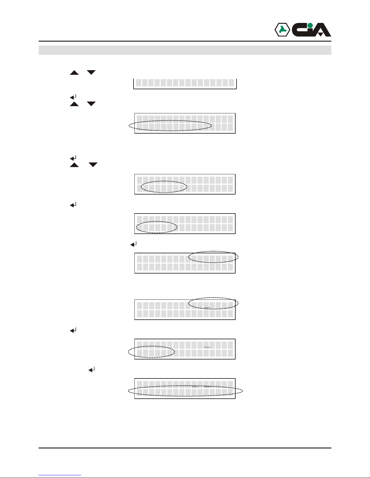
1. Enter to main menu pressing MASTER Code (default “1234”);
2. Press or until visualizing:
3. Press (or, to enter directly in programming “8” after Code);
4. Press or until visualizing:
Here it is possible to add cellular telephone numbers to which it will be send 6 SMS Messages of
alarm;
5. Press to enter;
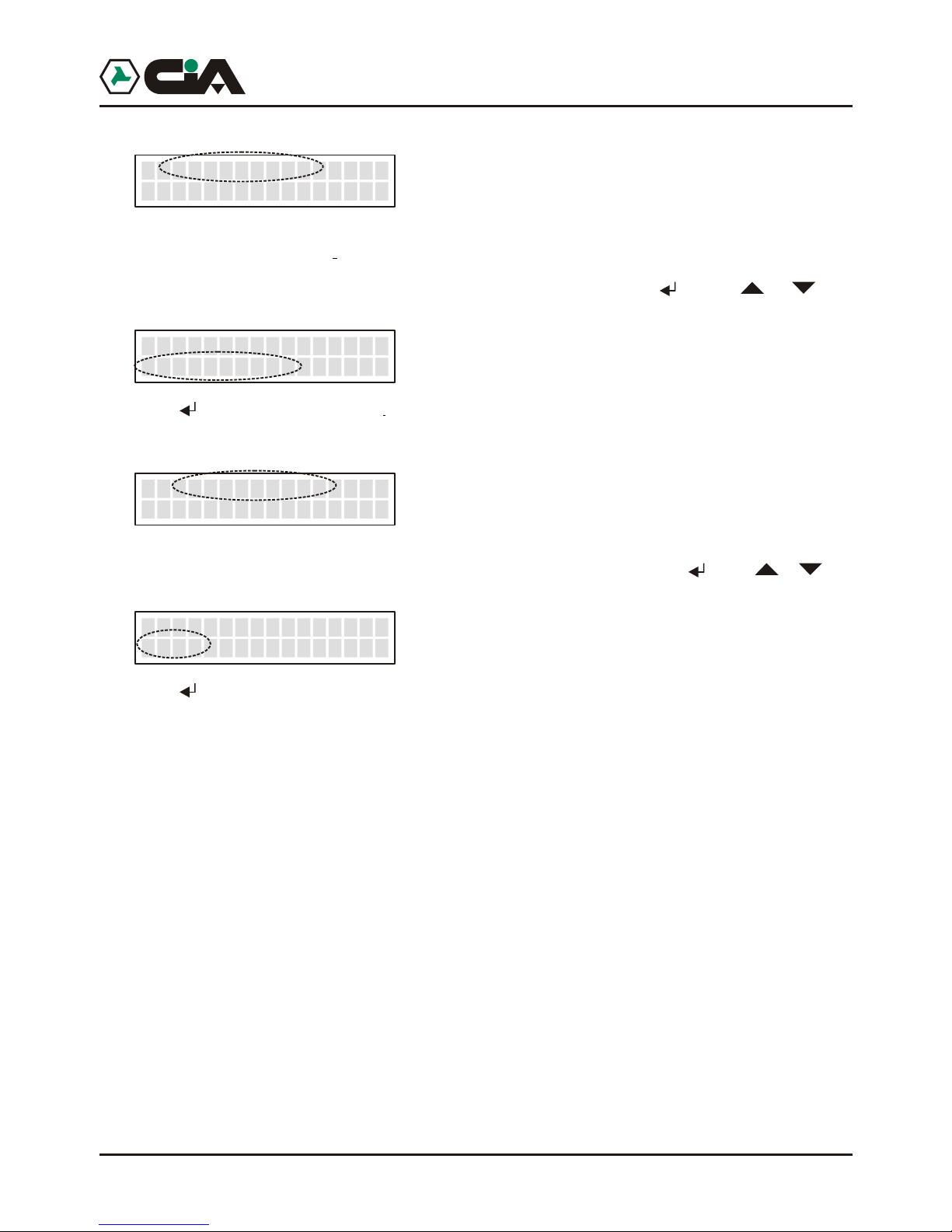
6. Press or until visualizing the cellular number of programming:
7. Press to insert the number:
8. Insert the number, so press to the allocation of the number to the channel:
9. Press from “1” to “6” it will be possible assign the number admitted to the channels visualized, for
example
10. Press :
11. Confirm with :
In this way, if channels 2 or 5 only are alarmed relative SMS message of alarm is forwarded to this
number .
To insert other numbers repeat operations from point 6.
8-PROGRAMMING
__
>PROGRAMMING<
Phonebook SMS
__
>PROGRAMMING<
Phonebook SMS
__
>PROGRAMMING<
Phonebook SMS
__
>PROGRAMMING<
Phonebook SMS
__
>PROGRAMMING<
Phonebook SMS
__
>PROGRAMMING<
Phonebook SMS
__
>PROGRAMMING<
Phonebook SMS
__
>PROGRAMMING<
Phonebook SMS
__
>PROGRAMMING<
Phonebook SMS
__
>PROGRAMMING<
Phonebook SMS
__
>PROGRAMMING<
Phonebook SMS
__
>PROGRAMMING<
Phonebook SMS
__
>PROGRAMMING<
Phonebook SMS
__
>PROGRAMMING<
Phonebook SMS
__
>PROGRAMMING<
Phonebook SMS
__
>PROGRAMMING<
Phonebook SMS
__
>PROGRAMMING<
Phonebook SMS
N.SMS 01>------
<Empty>
__
N.SMS 01>------
_
__
N.SMS 01>------__
3336667788
N.SMS 01>-2--5-__
3336667788
N.SMS 01>-2--5-__
Save
N.SMS_
__
_01>-2--5-
>> COMPLETED <<
11
3.1.3 Programming: Vocal Message
1. Enter to main menu press MASTER Code (default “1234”);
2. Press or until visualizing:
3. Press (or, to enter directly in programming “8” after Code);
4. Press o until visualizing:
Here it is possible record and listen again to Vocal Messages
5. Press to enter;
6. Press or until visualizing the message to record or listen again:
!Channel 1 - Channel 2 - … - are 6 (ERMES / TM60GSM) or 2 (TDC30 / TDC22 / TM20GSM)
vocal messages of alarm (of 15 seconds each one) that will be send to the activation of 6
(ERMES / TM60GSM) or 2 (TDC30 / TDC22 / TM20GSM) channels;
!Input INT SI - Input INT NO - are the 2 vocal message of state (of 2 seconds each one) that they
will communicate the two states of input INT;
!Input K1 SI - Input K1 NO - … - are the 12 (ERMES / TM60GSM) or 4 (TDC30 / TDC22 /
TM20GSM) vocal message of state (of 2 seconds each one) that they will communicate the
two states of everyone of the 6 (ERMES / TM60GSM) or 2 (TDC30 / TDC22 / TM20GSM) inputs;
!Out 1 SI - Out 1 NO - ... - are the 12 (ERMES / TM60GSM) or 4 (TDC30 / TDC22 / TM20GSM)
vocal message of state (of 2 seconds each one) that they will communicate the two states of
everyone of the 6 (ERMES / TM60GSM) or 2 (TDC30 / TDC22 / TM20GSM) outputs.
All the messages of state will be use to communicate the state of the system during Remote Control,
interrogating mobile telephone dialer by DTMF.
8-PROGRAMMING
__
>PROGRAMMING<
Vocal Messages
Channel 1
7-Play 9-Record
_
__
Input INT YES
7-Play 9-Record
_ ___
__
Input K1 YES
7-Play 9-Record
_ ____
__
Out 1 YES
7-Play 9-Record
___ ____
__
Programming
ERMES - TM60GSM - TDC30 - TDC22 - TM20GSM - User manual
10
3.1.2 Programming: SMS Directory
1. Enter to main menu pressing MASTER Code (default “1234”);
2. Press or until visualizing:
3. Press (or, to enter directly in programming “8” after Code);
4. Press or until visualizing:
Here it is possible to add cellular telephone numbers to which it will be send 6 SMS Messages of
alarm;
5. Press to enter;
6. Press or until visualizing the cellular number of programming:
7. Press to insert the number:
8. Insert the number, so press to the allocation of the number to the channel:
9. Press from “1” to “6” it will be possible assign the number admitted to the channels visualized, for
example
10. Press :
11. Confirm with :
In this way, if channels 2 or 5 only are alarmed relative SMS message of alarm is forwarded to this
number .
To insert other numbers repeat operations from point 6.
8-PROGRAMMING
__
>PROGRAMMING<
Phonebook SMS
__
>PROGRAMMING<
Phonebook SMS
__
>PROGRAMMING<
Phonebook SMS
__
>PROGRAMMING<
Phonebook SMS
__
>PROGRAMMING<
Phonebook SMS
__
>PROGRAMMING<
Phonebook SMS
__
>PROGRAMMING<
Phonebook SMS
__
>PROGRAMMING<
Phonebook SMS
__
>PROGRAMMING<
Phonebook SMS
__
>PROGRAMMING<
Phonebook SMS
__
>PROGRAMMING<
Phonebook SMS
__
>PROGRAMMING<
Phonebook SMS
__
>PROGRAMMING<
Phonebook SMS
__
>PROGRAMMING<
Phonebook SMS
__
>PROGRAMMING<
Phonebook SMS
__
>PROGRAMMING<
Phonebook SMS
__
>PROGRAMMING<
Phonebook SMS
N.SMS 01>------
<Empty>
__
N.SMS 01>------
_
__
N.SMS 01>------__
3336667788
N.SMS 01>-2--5-__
3336667788
N.SMS 01>-2--5-__
Save
N.SMS_
__
_01>-2--5-
>> COMPLETED <<
11
3.1.3 Programming: Vocal Message
1. Enter to main menu press MASTER Code (default “1234”);
2. Press or until visualizing:
3. Press (or, to enter directly in programming “8” after Code);
4. Press o until visualizing:
Here it is possible record and listen again to Vocal Messages
5. Press to enter;
6. Press or until visualizing the message to record or listen again:
!Channel 1 - Channel 2 - … - are 6 (ERMES / TM60GSM) or 2 (TDC30 / TDC22 / TM20GSM)
vocal messages of alarm (of 15 seconds each one) that will be send to the activation of 6
(ERMES / TM60GSM) or 2 (TDC30 / TDC22 / TM20GSM) channels;
!Input INT SI - Input INT NO - are the 2 vocal message of state (of 2 seconds each one) that they
will communicate the two states of input INT;
!Input K1 SI - Input K1 NO - … - are the 12 (ERMES / TM60GSM) or 4 (TDC30 / TDC22 /
TM20GSM) vocal message of state (of 2 seconds each one) that they will communicate the
two states of everyone of the 6 (ERMES / TM60GSM) or 2 (TDC30 / TDC22 / TM20GSM) inputs;
!Out 1 SI - Out 1 NO - ... - are the 12 (ERMES / TM60GSM) or 4 (TDC30 / TDC22 / TM20GSM)
vocal message of state (of 2 seconds each one) that they will communicate the two states of
everyone of the 6 (ERMES / TM60GSM) or 2 (TDC30 / TDC22 / TM20GSM) outputs.
All the messages of state will be use to communicate the state of the system during Remote Control,
interrogating mobile telephone dialer by DTMF.
8-PROGRAMMING
__
>PROGRAMMING<
Vocal Messages
Channel 1
7-Play 9-Record
_
__
Input INT YES
7-Play 9-Record
_ ___
__
Input K1 YES
7-Play 9-Record
_ ____
__
Out 1 YES
7-Play 9-Record
___ ____
__
Programming
ERMES - TM60GSM - TDC30 - TDC22 - TM20GSM - User manual
12
o record one of the messages, hold pressed “9” to start the record of the message:
It will be visualized the residual time of recording of the message. As soon as it comes left key “9” it will
be automatically reproduced the recorded message:
To listen again to messages, press or until visualizing the message to reproduce and press “7”:
NOTE:
When a channel will be alarmed mobile telephone dialer carries out a cycle of calls to all numbers in
Voice Directory link together to that channel to forward relative Vocal Message .
Parameter “Amount Cycles” described more ahead allows to establish how many times such cycle of
calls will have to be repeated. If during the sending of the vocal message it press “##”, the called
number will be excluded from subsequent eventual cycles; it will be carried out the only calls to which
answer has not been had, or those to which, in spite of the answer, it has not been press “##”.
It advisable therefore to insert at the end of recording Vocal Messages of alarm a note like: “...Press
twice cancelletto not to receive more this message of alarm”.
Channel 1
13.5
_
Channel 1
>>>>>>>>>>>>
_
Out 1 NO___ _____
>>>>>>>>
Programming
13
3.1.4 Programming: SMS Message
1. Enter to main menu pressing MASTER code (default “1234”);
2. Press or until visualizing:
3. Press (or, to enter directly in programming “8” after Code);
4. Press o until visualizing:
Here It is possible to program SMS Messages that will be send to the numbers SMS Directory, and
those of state that will be instead visualize only on display of ERMES / TM60GSM;
5. Press to enter;
6. Press o until visualizing message to program:
!Channel 1 - Channel 2 - … - they are the 6 (ERMES / TM60GSM) or 2 (TDC30 / TDC22 / TM20GSM) SMS
messages of alarm (of 100 characters eachone) that will be send to the activation of the 6 (ERMES /
TM60GSM) or 2 (TDC30 / TDC22 / TM20GSM) channels;
!Input INT SI - Input INT NO - they are the 2 messages of state (of 16 characters eachone) whom indicate on
display of mobile telephone dialer the two states of inout INT;
!Input K1 SI - Input K1 NO - … - they are the 12 (ERMES / TM60GSM) or 4 (TDC30 / TDC22 / TM20GSM)
messages of states (of 16 characters eachone) whom indicate on display of mobile telephone dialer the two
states of everyone of the 6 (ERMES / TM60GSM) or 2 (TDC30 / TDC22 / TM20GSM) inputs;
!Out 1 SI - Out 1 NO - ... - they are the 12 (ERMES / TM60GSM) or 4 (TDC30 / TDC22 / TM20GSM) messages
of states (of 16 characters eachone) whom indicate on display of mobile telephone dialer the two states of
everyone of the 6 (ERMES / TM60GSM) or 2 (TDC30 / TDC22 / TM20GSM) output.
NOTE: All the messages will be used to indicate on display the condition of the system during the
access to menu in the Local Control.
7. Press to insert the message; it will show a message that describes the name of channel:
8. To Compose the text of the message it is enough to press one of the keys to visualize in sequence on
display serigrafate letters on panel; the characters available are following:
8-PROGRAMMING
__
>PROGRAMMING<
SMS Messages
SMS Messages_
Channel 1_
CHANNEL 1
Channel 1
_
_
ABCabc2
DEFdef3
JKLjkl5 MNOmno6
TUVtuv8 WXYZwxyz9
+&@/%$_0
GHIghi4
PQRSpqrs7
?!,.:;”’<=>()1[spazio]
ERMES - TM60GSM - TDC30 - TDC22 - TM20GSM - User manual

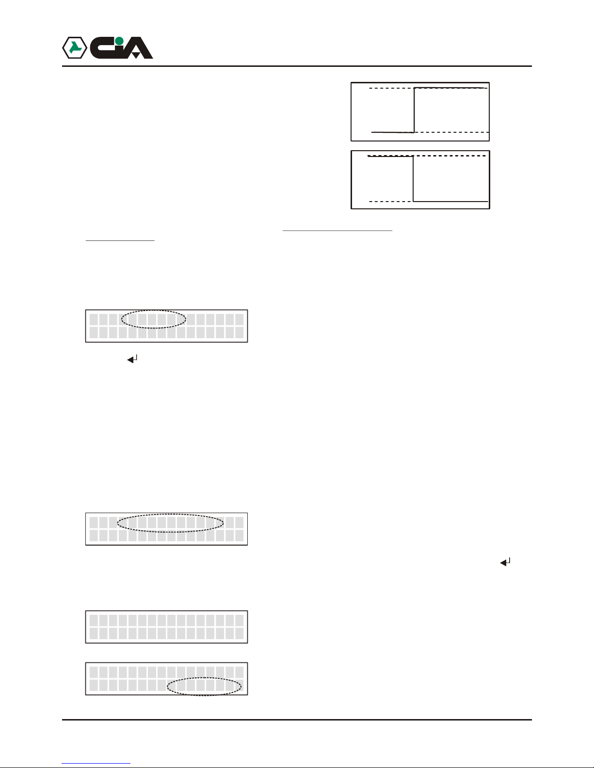
14
9. Use or move with slider to the inside of the message; pressing ESC it will be delate the part of
message between the slider and the end of the message . If the slider is at the end of the message
ESC delete the character who preceds the slider .
10. At the end press :
11. Confirm with :
3.1.5 Programming: Channels
1. To enter to menu press MASTER Code (default “1234”);
2. Press or until visualizing:
3. Press (or, to enter directly in programming “8” after Code);
4. Press or until visualizing:
Here it is possible to manage modalities of operation of inputs;
5. Press to enter;
6. Press or until visualizing the channel of which programming input:
7. Press ; Press e or until visualizing following parameters:
!Activation
Pressing the modality of activation of the channel between following will be able to be set up:
- Impulse NA
Tension impulse
- Impulse NC
Impulse of tension fall
Note: in modality Impulse, the activation of the channel makes to leave the
cycle of calls that persist until the term of calls, or until it has not been activated
CALLS STOP .
8-PROGRAMMING
_>PROGRAMMING<
Channels
PROGR. CHANNELS
Ch. 1 _
_
Ch. 1 Activacion
*Pulse NC
___
0
12 0,1sec min.
0
12 0,1sec min.
Channel 1
Save
Canale 1
>> COMPLETED <<
_
__
_
15
- Level NA
Forehead of fixed tension
- Level NC
Forehead of fall of fixed tension
Note: in modality Level, the cycle of calls actvated persists until it verifies the
state of input activation. At the restoration of input, the cycle of calls in course
will be interrupted.
- OFF
In OFF the channel is not operating; in this way the state of the channel will not be
visualize on display (like in example of page.8)
INT
Pressing the modality of activation between following will be able to be set up:
- Input Active
The activation of the channel is conditioned to the state of input INT.
Like in installation exemple, in coupling to a burglar central unit, it is possible to connect clip INT
with output +INT of central to concur with mobile telephone dialer to know the state inserition of
burglar system, and to send alarm message on channel 1 only to inserted system.
Moreover, in such configuration, relè Out 1 is conditioned to input 1: in this way the state of of
insertion of the burglar alarm is not employe from the physical state of relè, but rather this last one
exchanges until ‘feeling’ the state of insertion trough input INT.
- Input Disattivo
The activation of the channel is independent from whichever input.
Delay
It is possible to program the delay of the actvation until 9999 seconds on every input. Pressing it will
be possible to program the seconds of the duration of delay. After having insert the four figures, the
value will be automatically memorizzato. Once programmed the delay, at the actvation of the channel
will be visualized the residual time:
Ch. 1 INT
Input active
__
_
Ch. 1 Delay
*0095 Second
__
_
READY
>>>>> I TIM
----- C1
__
__
T 0094
>>>>> I TIM
----- C2
__
___
0
12
0
12
Programming
ERMES - TM60GSM - TDC30 - TDC22 - TM20GSM - User manual
16
3.1.6 Programming: Outputs
1. To enter to menu press MASTER Code (default “1234”);
2. Press or until visualizing:
3. Press (or, to enter directly in programming “8” after Code);
4. Press o r until visualizing:
Here it is possible to manage modalities of operation of outputs;
5. Press to enter;
6. Press o r until visualizing the output to program:
7. Press ; or until visualizing following parameters:
!Way
Pressing it will be possible to set up the modality of operation of output between following:
- ON/OFF
A local or remote commando of “ON” (key 7) active the output, a local or remote commando of
“OFF” (key 9) if input is disabled.
- ON/OFF >>Input
A local or remote commando of “ON” (key 7) active the output only if the input to which it is link
together is disabled and produce any effect if the input is active; a commando of “OFF” (key 9)
disabled the output only if the input to which it is link together is active and produce any effect if
the input is disabled.
- TOGGLE
A local or remote commando of “ON” or di “OFF” inverts the state of output.
- PULSE
A local or remote commando of “ON” or di “OFF” generates an impulse of duration from 0,1 to
9,9 seconds.
- PULSE >>Input
A local or remote commando of “ON” (key 7) generates an impulse of duration from 0,1 to 9,9
seconds only if the input of reference is not active it produce any effect if the input of reference is
active; a commando of “OFF” (key 9) generates the impulse only if the input of reference is
active, and it produce any effect if the input of reference is not active.
8-PROGRAMMING
_>PROGRAMMING<
Output
OUTPUT
Nm
PROGR.
.1_
_
Output 1 Mode
*ON/OFF >>Input
__
_
Programming
17
Modalities “with Input” are used in the connection example to command the insertion of a burglar
central unit in coupling to another system of commando (electronic key).
!Input
Once programmed the operation way, if this is of type “ON/OFF >>Input” or “PULSE >>Input”, press
or until visualizing:
Pressing , with keys and it will be possible to choose the input to which it will make reference
the output, and confirm it with .
!Duration
Once programmed the operation way, if this is of type“PULSE” o “PULSE >>Input”, press or
until visualizing:
Pressing it will be possible to program the seconds and the tenth of seconds of the duration of the
impulse.After having insert the two figures, the value it will be automatically recorded.
Output >>Input
*Input INT
_
_
Output >>Durat
*1.0 Second
_
_
ERMES - TM60GSM - TDC30 - TDC22 - TM20GSM - User manual
18
3.1.7 Programming: Parameters
1. To enter to men until visualizing:
3. Press (or, to enter directly in programming “8” after Code);
4. Press o r until visualizing:
Here it is possible to manage the parameters of operation of mobile telephone dialer;
5. Press to enter;
6. Press o r until visualizing one of the following parameters to program:
!P0: Amount Cycles
When a channel is alarmed, mobile telephone dialer carries out a cycles of calls to all the numbers
inserted on Voice Directory links together to the alarmed channel . Such parameter allows to establish
how many times such cycle of calls will have repeated.
In factory, such value is set up to 3; to modify it press :
Press a value between 1 and 9; the value will be recorded and it returns to the menu of parameters.
NOTE:
To every call mobile telephone dialer recognizes the happened answer and during the call (see
Remote Control) the pressing of two “##” recognizes to exclude the same call from eventual
subsequent cycles.
For which, during the cycles of subsequent calls will be carried out the only calls to which answer has
not been had, or those to which, in spite of the answer, it has not been pressed “##”.
!P 1: Amount Messages
It allows to establish the number of repetitions of the message to every call. In factory, such value is
set up to 3; to modify it press i :
Press a value between 1 and 9; the value will be recorded and it returns to the menu of parameters.
!
!
8-PROGRAMMING
_>PROGRAMMING<
Parameters
Q.ty Cycles
Nm
PO.1
__
_
Q.ty Cycles
Nm
PO.2
__
_
Q.ty Messages
Nm
PO.3
__
_
Q.ty Messages
Nm
PO.3
__
_
Programming
19
!P 2: ID Call
It allows to establish if the telephone number of SIM in GSM module of mobile telephone dialer must
be sent during the vocal call, that is those forwarding to the numbers of Voice Directory; logically such
parameter does not influence on the sending of SMS in which the number of the sender is always
visible. In factory, such value is set up on Visible; to modify it press ; press or until
visualizing:
Press ; the value will be recorded and it returns to the menu of parameters.
!P3: Answer
It allows to establish if mobile telephone dialer must answer automatically to the calls in input to carry
out the Remote Control. In factory, such value is set up on Si; to modify it press ; press o r until
visualizing:
Press ; the value will be recorded and it returns to the menu of parameters.
P2 ID Call
*Visible
__
P2 ID Call
*Hidden
__
P3 Answer
*ON
_
P3 Answer
OFF
_
*
ERMES - TM60GSM - TDC30 - TDC22 - TM20GSM - User manual
20
3.1.8 Programming: Codes
1. To enter to menu press MASTER Code (default “1234”);
2. Press o r until visualizing:
3. Press (or, to enter directly in programming “8” after Code);
4. Press o r until visualizing:
Here it is possible to modify the codes of access of mobile tele phone dialer (see par. 4.2 a pag.24);
5. Press to enter;
6. Press or until visualizing the access code parameters to modify:
!Code MASTER
It is the code with which it is possible to approach all the voices menu (see pag.9). In factory, such
value is set up to “1234”; to modify it press :
Press the four figures that compose new MASTER code to program; the value will be recorded and it
returns to the menu of parameters.
!Code COMMANDOS
It is the code with which it is possible to approach the single voice of menu COMMANDOS OUTPUTS
(see pag.9).In factory, such value is set up to “1234”; to modify it press :
Press the four figures that compose new COMMANDOS code to program; the value will be recorded
and it returns to the menu of parameters.
8-PROGRAMMING
_>PROGRAMMING<
Codes
Code MASTER_
Code MASTER
<
_
____>
Code MASTER
<Ok
_
__>2345
Code COMMAND_
Code COMAND
<
_
2345 __>
Code COMAND
<Ok
_
__>2345
21
Programming
3.1.9 Programming: CLIP
1. To enter to menu press MASTER Code (default “1234”);
2. Press o r until visualizing
3. Press (or, to enter directly in programming “8” after Code);
4. Press o r until visualizing:
Here it is possible to assign to the CLIP function to the telephone numbers present in SMS Directory;
in fact all the inserted telephone numbers in SMS Directory are visualized. From everyone it will be
possible to active one of the 6 commandos in output by a single ring forwarded towards the cellular
telephone number of mobile telephone dialer.
5. Press to enter;
6. Press or until visualizing the cellular number on which activating function CLIP:
It will not possible to activate function CLIP to the empty positions SMS Directory, as in following case:
7. Press :
8. At this point it is possible to assign the channel that it will be activated from the selected telephone
number, pressing a key from “1” to “6”;for example, “2”:
9. So, pressing “7” or “9” it will be possible to establish if the commando will be respective an activation
or a no activation of the output. For example, “7”:
8-PROGRAMMING
_>PROGRAMMING<
Clip
N. 01- 333445566
CL I P OF F_
_
N. 02- <Vuot o>
CL I P OF F_
_
N.01 3334455666_
CLIP OFF_
N.01 3334455666_
CLIP OUT -- OFF___
N.01 3334455666_
CLIP OUT2 -- ON___
ERMES - TM60GSM - TDC30 - TDC22 - TM20GSM - User manual
This manual suits for next models
4
Table of contents
Popular Conference Phone manuals by other brands


Yealink
Yealink CP860 SERIES quick start guide

Telelink
Telelink ESI IVX Conference Calls quick start guide

Intelix
Intelix Smartiphone DTA-201 user guide

Avaya
Avaya Vantage Installing and Administering

TRENDnet
TRENDnet TVP-SP4BK - ClearSky Bluetooth VoIP Conference... Quick installation guide

TELNET
TELNET Yealink CP935W user guide


