Cinemateq picture optimizer plus II User manual

picture optimizer plus II (SDI)
Video picture optimizer
User Manual
English
Version: 3.10

Table of contents
Important notes...........................................................................................................................................61
Introduction.................................................................................................................................................62
Support Hotline ..............................................................................................................................................62
Installation in 6 steps ...................................................................................................................................63
Step 1: Check scope of delivery ........................................................................................................................63
Step 2: Setup & connection.............................................................................................................................63
Step 3: Connection of other devices .................................................................................................................66
Step 4: First operational steps ........................................................................................................................69
Step 5: Operation elements & remote control ...................................................................................................69
Step 6: Basic configuration..............................................................................................................................71
Operation ....................................................................................................................................................78
General functions............................................................................................................................................78
Video switcher................................................................................................................................................78
Selecting the output format ............................................................................................................................79
Selecting the picture resolution (output resolution) ...........................................................................................82
TV-Mode.........................................................................................................................................................83
Electronic lensshift .........................................................................................................................................84
Overscan........................................................................................................................................................85
Configuration - the main menu .......................................................................................................................86
Input setup.....................................................................................................................................................86
Output setup..................................................................................................................................................90
Filter setup ....................................................................................................................................................94
Other options .................................................................................................................................................96
Configuration - the expert menu .....................................................................................................................97
Frame rates PAL / NTSC..................................................................................................................................97
Custom 1 / Custom 2 for PAL / NTSC ...............................................................................................................98
The optimum configuration ............................................................................................................................99
Connection of video sources & displaying device(s) .............................................................................................99
Resolution & frame rate ..................................................................................................................................99
Picture parameters & filters ..........................................................................................................................101
RS-232 control ..........................................................................................................................................103
Operation via RS-232....................................................................................................................................103
RS-232 control for other devices ...................................................................................................................104
Firmware upgrade ......................................................................................................................................105
Tips for error correction .............................................................................................................................107
Addendum.................................................................................................................................................110
IR control codes............................................................................................................................................110
Audio delay ...................................................................................................................................................110
Maintenance & care ......................................................................................................................................110
Warranty .....................................................................................................................................................111
Technical data...............................................................................................................................................113
61
IMPORTANT NOTES
Please read this user manual in detail in any case BEFORE connecting and taking the picture
optimizer plus II (SDI) into operation and consider all included set up and security notes.
Please keep this user manual in case you need to refer to it later on.
NEVER connect to and / or disconnect any other device from the picture optimizer plus II (SDI)
via the in- & outputs, before having switched off the picture optimizer plus II (SDI) and all other
devices and also having disconnected those from the main power supply. Otherwise irreparable
damages in any case excluded from warranty can happen to the picture optimizer plus II (SDI)
or other devices.
Always take care that all connections to the in- & outputs of the picture optimizer plus II (SDI)
are safely fixed and if possible screwed (VGA & DVI sockets) or protected (BNC sockets).
Especially DVI connections are extremely sensitive! “Wobbly“ connections can lead to
irreparable damages on the picture optimizer plus II (SDI) or other devices which are in any
case excluded from warranty.
Only use the external power adapter included in the scope of supply. Damages caused by third
party power supplies are excluded from warranty. Before connecting the external power
adapter to the main power supply it needs to be connected to the picture optimizer plus II
(SDI). Never disconnect power adapter and picture optimizer plus II (SDI) if the power adapter
is connected to the main power supply.
Changing the preset values for resolution and frame rate can lead to damages at the
connected displaying device in rare cases. Please in any case take into account the maximum
values, which can be processed by your displaying device and in exceed those in neither case
when adjusting the settings in the picture optimizer plus II (SDI) menu. Any liability from our
side for damages caused by such a behavior is excluded.
Only qualified service technicians are allowed to open the picture optimizer plus II (SDI) or the
power adapter included in the scope of delivery and perform service for the devices. Damages
caused by disregard are in any case excluded from warranty.
Warranty registration
In order to activate the two-year device warranty, you need to register your picture optimizer plus II
(SDI) at cinemateq within 4 weeks from purchase date.
Please therefore use the online registration form on www.cinemateq.com in the support section under
device registration.
Please note:
Only registered customers are informed by e-mail, when a new firmware (software) version and / or
new accessories for your device are available.
!
!
!
!
!
!

62
INTRODUCTION
Thank you very much
for your decision to use a cinemateq product. Congratulations for having bought a high quality device
designed in Germany and produced in the EU. As a specialist for quality picture and sound optimization of
home theater and presentation systems we warranty constantly high quality and trouble-free operation of
our products.
This user manual stepwise explains the installation and configuration of the cinemateq picture optimizer
plus II with / without SDI option and describes all functions and settings possible in detail. For further
information on the product itself, about configuration and tips & tricks in case of problems appearing
please refer to the support section on www.cinemateq.com.
In case of any technical questions or problems please contact your cinemateq authorized dealer. He
supports you with correct installation and best possible adjustment and / or set up of the device towards
your components and requirements. All of our cinemateq certified partners are especially trained by us for
best integration of the picture optimizer plus II (SDI) into new or existing systems.
SUPPORT HOTLINE
Besides our support hotline is available for technical questions and / or problems concerning cinemateq
products on weekdays from Monday to Friday during business hours from 9 a.m. – 5 p.m.. You can reach
our hotline by phone:
Germany: 0900 - 1742887 (0,98 € / minute)
Austria: 0900 - 454566 (1,55 € / minute)
Switzerland: 0900 - 980982 (2,50 CHF / minute)
or:
by fax: +49 (0)180 -5007226
(0,12 €/ minute, internationally reachable)
by e-mail: [email protected]
via web:
In the support section of www.cinemateq.com you will find the latest technical news and
downloads, useful tips and frequently asked questions & answers regarding our products for
your reference.

63
INSTALLATION IN 6 STEPS
STEP 1: CHECK SCOPE OF DELIVERY
First of all please check the contents of the packaging of your cinemateq picture optimizer plus II (SDI) in
order to make sure everything is included. The contents are:
picture optimizer plus II (SDI)
remote control
2 batteries for remote control (’AAA’)
external power adapter (230V ~50Hz)
user manual & quick installation guide in German and English
If a part is missing or should be damaged, please immediately contact your dealer. Please keep the
packaging in case you ever need to transport the picture optimizer plus II (SDI).
The picture optimizer plus II (SDI) is only configured and operated with the supplied infrared remote
control. Thus please first of all put the remote control into operation: Remove the cover of the battery
compartment on the back of the remote control, insert two type ’AAA’ (LR03) batteries and ensure the
right polarity (plus-poles point downwards). Close the battery compartment cover. The remote control is
now ready for use.
STEP 2: SETUP &CONNECTION
Setup
The picture optimizer plus II (SDI) should be positioned next to your video source(s), depending on the
length of the connection cables you have chosen.
nstatus LED (RED = Standby, BLUE = operation) oinfrared receiver for remote control pdisplay
The picture optimizer plus II (SDI) is only configured and operated by infrared remote control. Please
select a location in which there are no obstructions – such as cabinet doors or any other appliance – in
between the infrared receiver (o)and the remote control.
Please also make sure that you can see the picture of your displaying device whilst operating the picture
optimizer plus II (SDI) with the remote control as you will not be able to use the device’s on-screen menu.
Locations in other rooms or in closed cabinets are not recommended as they are – next to other things –
not suitable for operating the video switcher function of the picture optimizer plus II (SDI), despite you
are using a RS-232 control system.
Please in any case take into account the following security notes!

64
Security notes for setting up the picture optimizer plus II (SDI)
Set the picture optimizer plus II (SDI) onto a stable and flat surface.
Keep the picture optimizer plus II (SDI) away from radiators and other sources of heat and
protect it from direct sunlight.
If the picture optimizer plus II (SDI) is set up in a cabinet or similar, leave about 5 cm space
around the device, so that air can circulate unhindered in order to avoid accumulation of
heat.
Do not place any objects, little blankets or the like on the device, in order to avoid
accumulation of heat.
The picture optimizer plus II (SDI) should not be exposed to any drops or splashes of water
nor any objects filled with liquids (e.g. vases) should be placed on the device.
Connections
The picture optimizer plus II (SDI) is placed between video source(s) and displaying device(s):
The following devices are suitable for connection to the picture optimizer plus II (SDI):
Video sources (input) Displaying devices (output)
DVD player, DVD recorder
analog or digital VCR
SAT-, Pay-TV- or digital receiver
TV-Tuner or personal TV system
(e.g. FAST TV-Server)
video switchers or home cinema receivers
with video switch
game console
HDTV receiver (bypass only)
PC (bypass only)
CRT projector
digital DLP- or LCD-projector
plasma- or LCD-screen
TV with special “progressive input“
rear projection TV with progressive and / or
VGA input (for PC)
analog PC monitor
TFT monitor
!
65
The following interfaces and signal variants are offered for connecting the mentioned devices – the order
of interfaces equals the quality of the video signal transferred:
Inputs Outputs
2 x SDI* (BNC socket)
for SDI signals (digital)
2 x YUV** (3 Cinch socket)
for component signals (YUV)
2 x SCART (SCART socket)
for RGB or Composite (FBAS) signals
2 x S-Video (mini DIN connector)
for S-Video signals
2 x Composite (Cinch socket)
for Composite (FBAS) signals
1 x DVI (DVI socket)
with digital DVI output signal
1 x YUV (3 Cinch socket)
alternatively component (YUV) or RGsB
output signal
1 x RGB (5 BNC socket)
alternatively RGBHV, RGsB, RGBs or YUV
output signal
1 x VGA (VGA socket)
alternatively RGBHV, RGsB, RGBs or YUV
output signal
*) only picture optimizer plus II SDI (instead of the composite inputs) **) not suitable for progressive signals!
Please note:
All inputs only accept “interlaced“ signals, i.e. devices alike DVD players with a hard coded progressive
output (YUV) or PC (VGA) can not be connected to the video inputs! Please use the bypass inputs for
alike devices or connect those using another signal (e.g. S-Video).
Bypass inputs
The picture optimizer plus II (SDI) additionally integrates 2 so called bypass inputs, only passing through
the signal connected. This enables the connection of devices with progressive output signals (e.g.
progressive DVD players, PCs) or HDTV receivers (720p / 1080i) to the picture optimizer plus II (SDI) and
the switching together with the alternate 8 inputs. Please note that each bypass input can only transfer
a signal to the corresponding output interface as described in the following table:
Bypass input is transferred to:
VGA bypass (VGA socket)
for „pass through“ of RGBHV, RGsB, RGBs or YUV
signals
VGA output (VGA socket)
RGB bypass (5 BNC sockets)
for „pass through“ of RGBHV, RGsB, RGBs or YUV
signals
RGB output (5 BNC sockets)
About SDI
The picture optimizer plus II SDI integrates two digital SDI inputs. SDI - Serial Digital Interface - is a 10-bit
interface for transfer of digital video data originally developed by Sony. The SDI standard is also known as
SMPTE 259M. SDI up to now is mainly used in professional video- and studio technology and enables loss-
free transfer of video- (but also audio-) signals over larger distances. Both DVD players and SAT-/cable
receivers can be modified for distribution of data in SDI data streams.
The crucial advantage is, that SDI is the one and only digital standard input signal being enabled to
transfer an unadulterated 1:1 rendition of the digital video signal of DVD or digital TV without any loss in
quality even over larger distances.

66
STEP 3: CONNECTION OF OTHER DEVICES
Preparation of devices to be connected
In order to ensure a perfect video picture optimization the picture optimizer plus II (SDI) needs the video
signal coming from the video source with certain “attributes” as a prerequisite and the displaying device
is meant to render the optimized output signal of the picture optimizer plus II (SDI) without
“interference“ (e.g. by filters applied).
Therefore you should check and prepare your video source(s) and your displaying device before connecting
them to the picture optimizer plus II (SDI).
Video source (e.g. DVD player, SAT receiver)
First connect the source directly to the displaying device without the picture optimizer plus II (SDI) in
order to be able to access the on-screen menu of the video source:
1. The picture optimizer plus II (SDI) needs an unfiltered and unchanged video signal. Therefore we
recommend to switch off all picture influencing filter functions such as “noise reduction” via the
set up menu of your video source (e.g. DVD player). Please refer to the user manual of your video
source to find out which filter- and / or picture optimizing functions are available.
2. In case your video source has an integrated “aspect ratio conversion“ (mostly DVD players),
please set the output format to 16:9 (not 4:3 or „letterbox“) in the set up menu in either case.
3. The picture optimizer plus II (SDI) can only process “interlaced“ signals. If you do not only want to
pass through the signal of a progressive video source by using the bypass input of the picture
optimizer plus II (SDI), in neither case use a “progressive output“ for connection and / or switch
off the “progressive function“ in the device’s set up menu.
4. In case you want to connect your video source using the SCART input of the picture optimizer
plus II (SDI), you should set the SCART output of your video source to RGB output in the device’s
set up menu (e.g. AV output = RGB). If your video source doesn’t support RGB output via SCART
(e.g. only S-Video or Composite), you should – if possible – chose another connection (such as YUV
or S-Video output). Please only use a Composite signal via SCART, if there is no other connection
available (therefore the SCART input of the picture optimizer plus II (SDI) needs to be set to
“Composite“, see page 72).
5. The best possible connection between video source and picture optimizer plus II (SDI) is a digital
connection via SDI as it transfers the digital video signal unchanged (1:1). As an analog
connection we recommend either RGB (via SCART) or YUV (via 3 x Cinch). S-Video or Composite
connections deliver a minor quality signal.
Displaying device (e.g. projector, plasma)
Now please configure the displaying device – still without picture optimizer plus II (SDI):
1. If your displaying device integrates picture influencing filters and optimizing functions, switch
those off also in the device’s set up menu. Eventual “Key Stone Correction“ or “Overscan“
settings should be switched off or set to neutral for the time being.
2. We also recommend to set all picture parameters (such as brightness, contrast etc.) to neutral
for the time being as the picture optimizer plus II (SDI) transfers the optimized video signal with
different picture values.
3. The picture format conversion should be adjusted to the displaying device’s format (if 16:9 to
16:9 and / or “normal“, if 4:3 to 4:3 or “full picture“).
4. The optimal connection between the picture optimizer plus II (SDI) and your displaying device is a
digital connection via DVI. In case your device has no digital DVI interface, please check which
signal format “YUV“ or “RGB“ (RGB HV, RGBs, RGsB) is accepted by which analog interface (VGA,
3 x Cinch or 5 x BNC) of your device and choose on of these options. These settings afterwards
also need to be “mirrored” in the picture optimizer plus II (SDI) setup later on. The best quality
connection depends on your displaying device, under www.cinemateq.com in the support section
you can find recommendations of our testers for the most common displaying devices.

67
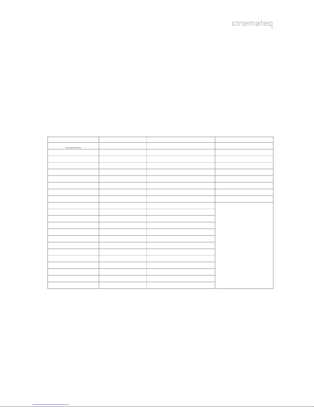
Connection
The picture optimizer plus II offers the following interfaces, at the picture optimizer plus II SDI the two
Composite inputs (r) are replaced by two SDI inputs (BNC socket):
Description Interface Signal format
SCART 1
qSCART 2 SCART socket Alternatively for RGB or Composite signals
(factory set SCART 1 = RGB, SCART 2 = Composite)
Video 1 (SDI 1)
rVideo 2 (SDI 2)
Cinch socket
(SDI = BNC socket)
for Composite (FBAS) signals
(SDI: for SDI signal Level C)
S-Video 1
sS-Video 2
S-Video socket
(mini DIN-4) for S-Video signals
YUV 1
tYUV 2 3 x Cinch socket for YUV (component) signals
ubypass BNC 5 x BNC socket for RGB HV, RGBs, RGsB or YUV signals
vbypass VGA VGA Socket for RGB HV, RGBs, RGsB or YUV signals
woutput RGB 5 x BNC socket for RGB HV, RGBs, RGsB or YUV signals
output VGA VGA socket for RGB HV, RGBs, RGsB or YUV signals*
output YUV 3 x Cinch socket for RGBs, RGsB or YUV signals
output DVI 1 x DVI-D socket for digital DVI signals
remote interface 1 x RS232 socket Serial data signal for firmware upgrade / control commands
On-/Off switch - -
connector for external
power adapter (12 V) - -
* some displaying devices can not process a YUV signal transferred by VGA interfaces, despite you use a special VGA cable, that is not
transferring the H & V sync
Now connect your video source to the picture optimizer plus II (SDI) using the connection chosen by you
before. For the first operational steps we recommend to connect only one source to the SCART 1 input,
as the SCART 1 input (with RGB signal) is set as the active input in the factory settings.
Afterwards connect your displaying device to the picture optimizer plus II (SDI). A RGB HV signal (via the
VGA or 5x BNC interface) is distributed by the picture optimizer plus II (SDI) in factory setting condition.
Security notes for connecting other devices
NEVER connect to and / or disconnect any other device from the picture optimizer plus II
(SDI) via the in- & outputs, before having switched off the picture optimizer plus II (SDI) and
all other devices and also having disconnected those from the main power supply. Otherwise
irreparable damages - in any case excluded from warranty - can happen to the picture
optimizer plus II (SDI) or other devices.
Always take care that all connections to the in- & outputs of the picture optimizer plus II
(SDI) are safely fixed and if possible screwed (VGA & DVI sockets) or protected (BNC
sockets). Especially DVI connections are extremely sensitive! “Wobbly“ connections can lead
to irreparable damages on the picture optimizer plus II (SDI) or other devices which are in
any case excluded from warranty.
11
12
13
14
15
16
qu v 14
r s t15 16
s
r t w11 12 13
q
!

68
TIP:
We recommend to always connect the picture optimizer plus II (SDI) directly to the displaying device
– video switchers or audio-/video home cinema receivers connected in between can deteriorate
picture quality.
We recommend to use high quality cables, as the quality of signal transfer via cable is a crucial
factor in video picture optimizing. Fitting connection cables and adapters for all in- and outputs are
available at your specialized dealer.
For DVI connections longer than 10m we recommend the cinemateq DVI Link cables with optical
transmission via fiberglass, available at all cinemateq dealers.
For automatic switching of more than one DVI sources towards a DVI enabled displaying device (e.g.
picture optimizer plus II (SDI) and HDTV receiver with DVI) we recommend the cinemateq DVI Link
switchers.
Mains voltage
After having connected the picture optimizer plus II (SDI) with all video
sources and displaying devices, connect the power adapter. Please take care
that
the power adapter must not be connected to the main power
supply, when connecting it to the picture optimizer plus II (SDI).
the On-/Off switch ( ) of the picture optimizer plus II (SDI)
is set to “OFF“.
After having connected the power adapter, connect it to the main power
supply. Your picture optimizer plus II (SDI) is now ready for the first
operational steps.
Security notes for connecting the power adapter
Before connecting the external power adapter to the main power supply it needs to be
connected to the picture optimizer plus II (SDI). Never disconnect power adapter and picture
optimizer plus II (SDI) if the power adapter is connected to the main power supply.
Only use the external power adapter included in the scope of supply – other power adapters
can cause damages to the device.
Only qualified service technicians are allowed to open the external power adapter and
perform service for the device.
Ensure, that the power adapter never gets in contact with liquids, combustible objects or
gases of neither composition nor is placed next to any of those.
Place the power adapter in a way that ensures a minimum of 5 cm space around the device
in order to avoid accumulation of heat.
If you don’t use the picture optimizer plus II (SDI) for a longer time please disconnect the
power adapter from the main power supply.
!
15
69
STEP 4: FIRST OPERATIONAL STEPS
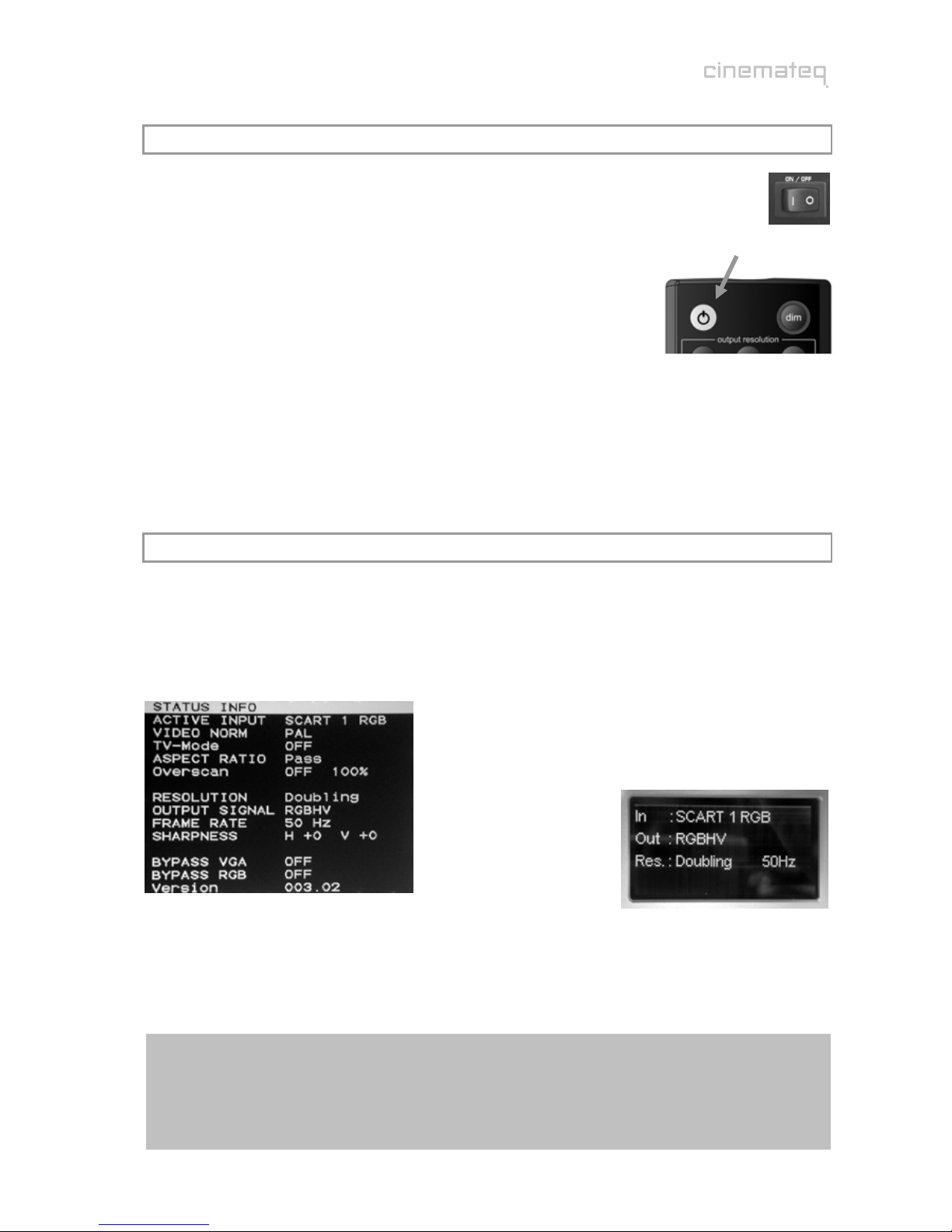
Your picture optimizer plus II (SDI) is now ready for the first operational steps. To switch the
device on, please set the power switch on the device’s back panel to “ON“ first. The picture
optimizer plus II (SDI) is now in “stand by mode“, the status LED on the device’s front side
shines “RED“, the display is switched off yet.
Now switch on the connected video source and your displaying device and
take care, that the video source distributes a signal (e.g. DVD player: insert
DVD and press “Play“).
Next “wake up” the picture optimizer plus II (SDI) out of “stand by mode“
using the power key on the remote control. The status LED starts flashing
RED / BLUE, after about 5 seconds the display is switched on and shows
the basic status info.
Your picture optimizer plus II (SDI) is now ready for use (= “operating mode“) and can be configured
towards your connected devices.
STEP 5: OPERATION ELEMENTS &REMOTE CONTROL
Operation elements
The operation and configuration of the picture optimizer plus II (SDI) is performed via the on-screen menu
and / or the graphical info display integrated into the device’s front panel, showing the same content like
the on-screen menu in a compact format.
on-screen menu (status info) info display (status info)
On account of simplicity in the following explanations and pictures we nearly exclusively refer to the
clearer on-screen menu, despite it is not visible in the configuration steps.
Please note:
The on-screen menu of the picture optimizer plus II (SDI) is optimized for rendition in ”doubling“
resolution. When rendering in another resolution a slight optical “distortion” is shown appearing as a
horizontal or vertical stretching and / or compression.
This is NO error of the device, but a technically caused variation of rendition.

70
Remote control
on / s
t
andb
y
dim
controls brightness of
the display
numeric keys
for direct entering of
values into dialog boxes
additionally:
input selection
direct access to 8
inputs using the corres-
ponding numeric key
output resolution
via [option] + [corresp.
key] selection of output
resolution
Navigation cross
Navigation and adjust-
ment of values in
menus and dialog boxes
[OK] in addition to that
displays the on-screen
status info
additionally:
[option] + [+]/[-]
switches on and off the
VGA-Bypass ([-]) and /
or the RGB-Bypass ([+])
electronic lensshift
[option] + [▲]/[▼]
activates the
“electronic lensshift“
function up- or
downwards
exit
closes dialogs without
saving changes and / or
removes the on-screen
menu or status info
additionally:
TV-Mode ON / OFF
via [option] + [exit] TV-
Mode is activated, via
[exit] deactivated again.
option
[option] activates the
„second function“ of
various keys, e.g. the
selection of the output
resolution
Overscan ON / OFF
via the [+78V] key the
Overscan function is
switched on and off.
menu
1 x: Main Menu
2 x: Ex
p
ert-Menu
aspect ratio
conversion
direct access to format
conversions.
Please note:
The [+78V] is hard
coded to the “overscan“
function
71
STEP 6: BASIC CONFIGURATION
In this step you will learn, how the picture optimizer plus II (SDI) is configured towards the connected
devices in order to reach a correct picture rendition.
An optimal picture rendition using the full spectrum of the picture optimizer plus II (SDI) needs further
adjustments – please refer to the point “The optimum configuration“ (from page 99 on).
Factory settings
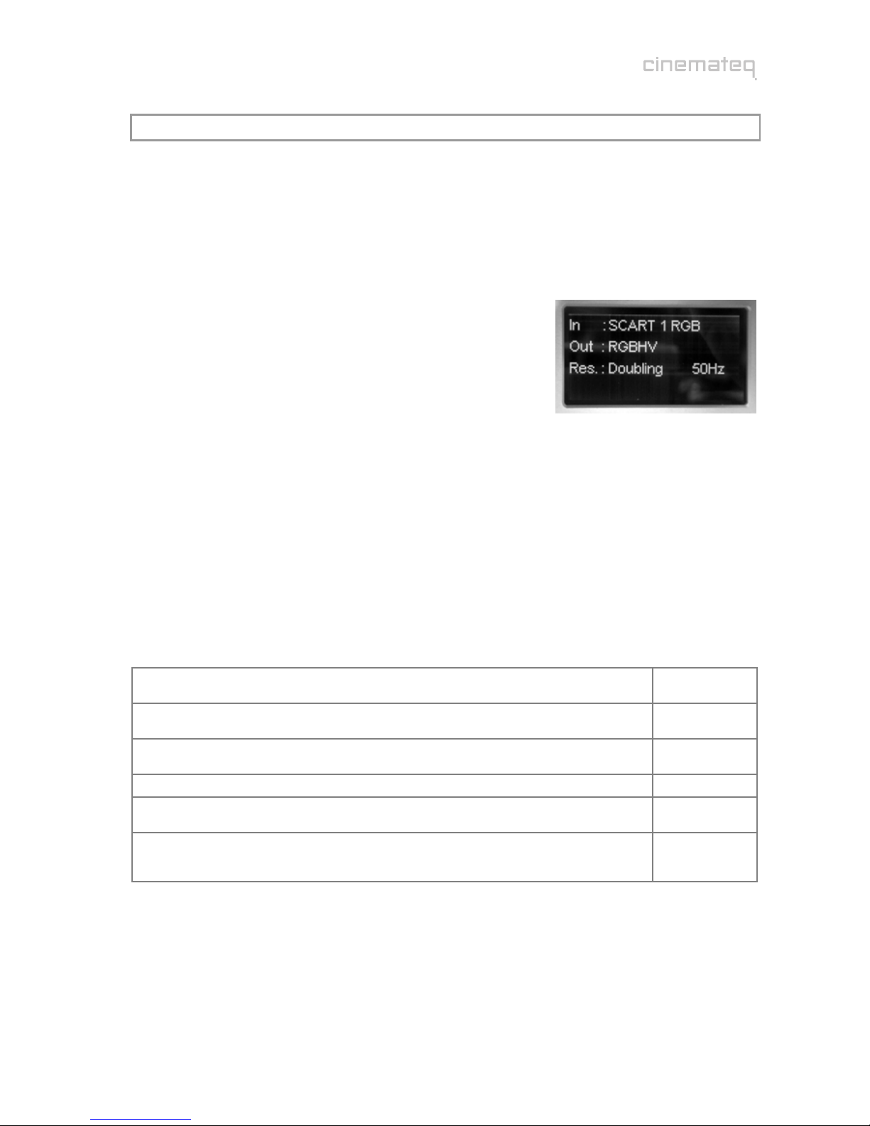
The most important basic settings are shown in the “status info“ in
the display of the picture optimizer plus II (SDI):
IN: SCART 1 RGB
SCART 1 is set as active input with RGB signal in factory set
up.
Out: RGB HV
The output format is set to RGB HV in factory set up. This
signal is always distributed by all outputs enabled for this. In
case of RGB HV: VGA and 5 x BNC.
Res.: Doubling 50 Hz
The output resolution is set to “doubling“ (PAL: 576p / NTSC: 480p) with a frame rate of 50 Hz in
PAL (NTSC: 60Hz).
If you have connected your devices according to these factory settings and can already see the picture of the
video source on your displaying device, you can pass by the point “Connection configuration“.
Connection configuration
Before starting, please review the following check list and if necessary enter your values into the table:
(A) Which input of the picture optimizer plus II (SDI) is the video source you used for basic
configuration connected to (we recommend a DVD player)?
(B) In case it is the SCART 1/2 input: Which signal format (RGB / Composite) is the video source
distributing via SCART?
(C) In case it is the YUV 1/2 input: Is a possible progressive output of the video source via its
YUV output deactivated?
(D) Which interface (VGA, DVI, 5 x BNC, 3 x Cinch) is your displaying device connected to?
(E) Which video signal format (RGB HV, RGBs, RGsB, YUV, digital DVI) does your displaying
device accept on this interface?
(F) Incase using YUV connections via 3 x Cinch (input or output): Are the cables connected
correctly to the picture optimizer plus II (SDI) and video source / displaying device?
”Y“ = Green, “U“ (Pb) = Blue, “V“ (Pr) = Red

72
Connection video source Îpicture optimizer plus II (SDI)
First, please choose the input your video source is connected to
as “active input“ (A).
Therefore press the corresponding input key on the remote
control (see table), e.g. key [5] for the
”S-Video 1“input.
The status info in the display accordingly changes into:
In: S-Video 1
The input for your connected video source is now activated.
If you can now see a picture on your displaying device, you can directly jump to the point “Resolution &
frame rate“ on page 99.
Conversion of the SCART inputs between RGB ÙComposite
A SCART interface can transmit different signals. The picture optimizer plus II (SDI) either understands
RGB- (highest quality variant) or Composite signals via its SCART inputs. Factory setting are:
SCART 1 with RGB
SCART 2 with Composite
If you use either of the two SCART inputs and transmit a Composite signal on SCART 1 and / or a RGB
signal as input signal on SCART 2, you need to change the allocation of the SCART input in the input menu
of the picture optimizer plus II (SDI).
(1) Therefore please press the [menu] key on the remote control
once. The “Main Menu“ selection appears in the display.
(2) Select “Input Setup“ using the [▲] / [▼] keys and confirm this by
pressing the [OK] key.
(3) Now select the menu point “General Input Setup“ using the
arrow keys again and press the [OK] key.
(4) With the arrow keys now select the menu point “SCART 1“ and /
or “SCART 2“and press the [OK] key.
(5) The currently set value (“RGB“ / “Composite“) is now highlighted
in a blue bar, select the desired value with the [+] / [-] keys and
activate it by pressing the [OK] key.
(6) By three times pressing the [exit] key you close all menus and
get back to the status info.
After again confirming the input via the numeric keys on the remote control the status info in the display
changes accordingly to: In: SCART 1 Comp. and / or In: SCART 2 RGB
input access via
remote control key
SCART 1 1
SCART 2 2
Video 1 / SDI 1 3
Video 2 / SDI 2 4
S-Video 1 5
S-Video 2 6
YUV 1 7
YUV 2 8

73
Connection picture optimizer plus II (SDI) Îdisplaying device
Next configure the used outputs interface
to the signal format required by your
displaying device.
The picture optimizer plus II (SDI) offers 4
output interfaces with different signal
formats (see table).
First, please check, if the selected interface
can transmit the signal format required by
the displaying device (3 x Cinch e.g. can not
transmit a RGB HV signal).
If the (cable-) connection between picture
optimizer plus II (SDI) and displaying device
is correct (consider socket allocation!), now
adjust the required signal format via the
output setup:
(1) Therefore please press the [menu] key on the remote control
once. The “Main Menu“ selection appears in the display.
(2) Select “Output Setup“ using the [▲] / [▼] keys and confirm this
by pressing the [OK] key.
(3) Now select the menu point “Output signal“ using the arrow keys
again and press the [OK] key.
(4) The currently set value (“RGBHV“) is now highlighted in a blue
bar, select the desired value (e.g. “YUV”) with the [+] / [-] keys and
activate it by pressing the [OK] key.
(5) By two times pressing the [exit] key you close all menus and get
back to the status info.
The status info in the display changes to: OUT: YUV
Now the connection video source Îpicture optimizer plus II (SDI) Îdisplaying device is configured
according to your needs and the displaying device should show the video source’s picture signal.
In case you can’t see the video source’s picture signal yet, please check the following:
Do you see the on-screen menu, if you press the [menu] key once? (close with [exit] key)
In case “Yes”, the connection to the displaying device is in any case available, i.e. your video source
either transmits no signal,
is connected to another (than the currently active) input
or the connection is not correct (e.g. SCART RGB / Composite conversion, YUV with exchanged
cables or similar) and / or a cable is possibly broken.
In case “No”, the displaying device can not yet render the picture optimizer plus II (SDI) output signal. The
following reasons can apply:
The displaying device only recognizes an input with active signal automatically immediately after
having been switched on (manually select the input at the displaying device).
A faulty connection (e.g. YUV with exchanged cables or even a defective cable) and / or the
selected signal format (e.g. RGB HV) is not supported by the displaying device.
Some digital displaying devices via their DVI or VGA input do not “understand” the “doubling“
(576p / 480p) resolution at 50 Hz that is preset in factory set up at the picture optimizer plus II
(SDI). Next you will learn, how the resolution is adjusted to your displaying device.
signal format via interface
RGB HV
(factory
setting)
5 x BNC socket
VGA socket
RGBs 5 x BNC socket (“R“, “G“, “B“, “H“ only)
VGA socket
RGsB
RGsB 3
(tri-level sync)
5 x BNC socket (“R“, “G“, “B“ socket only)
3 x Cinch socket (Y = “R“, U = “G“, V = “B“)
VGA socket
YUV
YUV 3
(tri-level sync)
3 x Cinch socket
5 x BNC socket (R = “Y“, G = “U“, B = “V“)
VGA socket
DVI DVI-D socket

74
Resolution & frame rate
After having configured the picture optimizer plus II (SDI) towards the requirements of your connected
devices and the displaying device shows the video source’s picture signal, you should set the “right“
resolution for your displaying device.
The major target in basic configuration is to get an acceptable picture. You will learn more about how the
picture optimizer plus II (SDI) is adjusted to your displaying device in the best possible manner in regards
to connection, resolution and frame rate under the point „The optimum configuration“ (from page 99 on).
If you already see a picture signal on the displaying device, please go to the point “Adjustment of the right
resolution“ (page 75). In case there is no picture yet, you should first detect the reason for that before
selecting different resolutions.
Picture signal is not shown
The picture optimizer plus II (SDI) is set to “doubling“ resolution in its factory settings (equals the
standard video resolution 576p) at a frame rate of 50 Hz for PAL signals (NTSC: 480p at 60 Hz).
This resolution is accepted by all analog and most of the digital displaying devices. However some digital
displaying devices do not “understand“ a video resolution like “doubling” at their DVI and VGA input, as
these interfaces were only meant for PC signals in these cases and can’t recognize video signals.
Please test the following resolutions one after the other. Therefore first press the [option] key on the
remote control and then – within 3 seconds – the according numeric key (take care that only the status
info is shown in the display, if necessary close all menus shown by pressing the [exit] key):
“doubling“ (576p / 480p) Î[option] + [1]
“720p“ (1280 x 720p) Î[option] + [4]
“1080i“ (1920 x 1080i) Î[option] + [7]
If none of these resolutions show a picture signal, the displaying device does not accept video resolutions
and / or the selected signal format over the used interface (all other sources for errors like faulty
connections, defective cables or an incompatible signal format should be excluded).
In this case please (for the time being*) connect the displaying device via a different interface and / or a
different signal format to the picture optimizer plus II (SDI). For example change from DVI to YUV or from
VGA (RGB HV) to VGA (RGBs) and / or from YUV to RGB HV via 5 x BNC socket etc.
*) probably the initial connection variant can though be used via a “custom resolution“, find more in the point “Expert Menu“ (from page 97
on)
With a different connection and one of the above mentioned resolutions you should normally get a picture
signal at the displaying device.
Please note:
In case the above mentioned resolutions do neither lead to a result with different connections,
unfortunately there may be a (very rare) incompatibility: Your displaying device can not render
progressive video signals. In exceptional cases such devices can nevertheless be accessed by using a
special “custom resolution“. Please contact your specialized dealer and / or the cinemateq support
hotline.
75
Adjustment of the right resolution
Crucial for the picture quality of the displaying devices is the addressing with the “right” resolution. This
means the resolution, at which the displaying device can render the video picture without further
conversion errors. Best case for digital devices (such as LCD-/ DLP projectors, plasmas etc.) this is the
so called “native“ resolution, i.e. exactly the physical pixel resolution of the displaying device’s “panel“.
Unfortunately the native resolution does not work with all devices as the control electronics can not
process it. Here it applies to find the best possible compromise.
Please first check, which “native resolution“ (also called panel resolution) your displaying device has (e.g.
XGA 1024 x 768) – this information can be found in the technical data of the device.
Next select the resolution, that comes nearest to this “native resolution“ in the following table. The
picture optimizer plus II (SDI) offers 22 different predefined resolutions for both PAL and NTSC signals.
resolutions table
resolution H x V max. frame rate * PAL / NTSC access via
Doubling 1440 x 576p 100 Hz / 120 Hz [option] + [1]
Tripling 1440 x 864 / 720p 75 Hz / 90 Hz [option] + [2]
Quadrupling 1440 x 1152 / 960p 50 Hz / 72 Hz [option] + [3]
HDTV 720p 1280 x 720p 100 Hz / 120 Hz [option] + [4]
XGA 1024 x 768p 100 Hz / 120 Hz [option] + [5]
SXGA (5:4) 1280 x 1024p 75 Hz / 72 Hz [option] + [6]
HDTV 1080i 1920 x 1080i 100 Hz / 120 Hz [option] + [7]
custom 1: 480p 1440 x 480p 100 Hz / 120 Hz [option] + [8]
custom 2: Wide-XGA 1280 x 768p 100 Hz / 90 Hz [option] + [9]
Wide-VGA 852 x 480p 100 Hz / 120 Hz
540p 960 x 540p 100 Hz / 120 Hz
576p 720 x 576p 100 Hz / 120 Hz
576i / 480i 1440 x 576i/480i 100 Hz / 120 Hz
SVGA 800 x 600p 100 Hz / 120 Hz
Wide-XGA 2 1365 x 768p 100 Hz / 90 Hz
Wide-XGA 3 1366 x 768p 100 Hz / 90 Hz
SXGA (4:3) 1280 x 960p 100 Hz / 120 Hz
PDP 1 852 x 1024p 100 Hz / 120 Hz
PDP 2 1024 x 1024p 100 Hz / 120 Hz
DILA 1366 x 1024p 75 Hz / 72 Hz
UXGA (4:3)** 1600 x 1200p 50 Hz / 50 Hz
HDTV 1080p** 1920 x 1080p 50 Hz / 60 Hz
menu
* if transmitted via DVI max. 50 Hz / 60 Hz; ** Distribution via analog outputs only
You can activate the selected resolution using the remote control and according key code. In case the
selected resolution is not allocated to any of the keys (see table), you first need to allocate it to the
resolutions key [custom 2] (= key [9]) in the menu (see example 1 & 2).
Example 1: “XGA“ (1024 x 768)
First press the [option] key on the remote control and then within 3 seconds the corresponding numeric
key:Î[option] + [5]
Take care that during this procedure only the status info is shown in the display, if necessary close shown
menus by pressing the [exit] key.

76
Example 2: „WVGA“ (852 x 480)
This resolution first needs to be allocated to the resolutions key [custom 2] in the menu. Proceed as
follows:
(1) Therefore please press the [menu] key on the remote control
once. The “Main Menu“ selection appears in the display.
(2) Select “Output Setup“ using the [▲] / [▼] keys and confirm this
by pressing the [OK] key.
(3) Now select the menu point “Res. Custom 2“ using the arrow
keys again and press the [OK] key. The currently set resolution value
(e.g. “WXGA1“) is now highlighted in a blue bar and / or orange in
the on-screen menu.
(4) Using the [+] / [-] keys you can now navigate amongst all
predefined resolutions. Select the desired resolution (e.g. “WVGA”)
with the [+] / [-] keys and activate it by pressing the [OK] key.
(5) By two times pressing the [exit] key you close all menus and get
back to the status info.
Now the selected resolution (e.g. “WVGA“) is allocated to the resolutions key [custom 2], the initial value
has been overwritten. You only need to activate the new resolution by pressing the [option] key and then
within 3 seconds the numeric key [9] (=[custom 2]):Î[option] + [9]
In case no picture is shown after having activated the selected resolution, your displaying device does not
understand the selected resolution. Please go back to the initially set resolution (doubling, 720p or
1080i) and test another resolution coming near to your “native resolution“. Eventually a different
connection variant towards the displaying device may help: some devices unfortunately don’t understand
“PC-resolutions“ such as “XGA“ or “SXGA“ via a YUV signal.
Many digital displaying devices also work perfectly with one of the two HDTV resolutions 720p or 1080i,
i.e. these are displayed by the device without “errors“. This is an alternative you should try in any case as
for the time being it is the only “resolution standard“ most of the display manufacturers stick to.
Increasing the frame rate
Increasing the standard frame rate of 50Hz for PAL and / or 60Hz for NTSC signals lead to an
improvement of picture quality at analog displaying devices such as CRT projectors depending on the
selected resolution (e.g. elimination of “picture flickering“).
For digital devices (plasmas, LCDs, DLP projectors etc.) we strongly recommend to NOT increase the
frame rate of 50 Hz (PAL) and / or 60 Hz (NTSC)!
Here a higher frame rate leads to picture deteriorations such as “judder“ in moving pictures (DVD /
cinema) or “double edges“ (at TV pictures).
We recommend to use the
following frame rates for
analog displaying devices
depending on the
application, in case they are
supported by the selected
resolution (see resolution
table):
analog displaying devices
Recommendation PAL NTSC
Best possible quality for cinema (DVD) 75 Hz 72 Hz
Recommendation for TV, but slight “flickering“ 50 Hz 60 Hz
Good compromise for cinema & TV, but slight
unsharpness & double edges with TV signals 100 Hz 120 Hz

77
In case you want to change the frame rate for a certain resolution, please proceed as follows. Take into
account the maximally possible values for each resolution (see resolutions table).
(1) Therefore please press the [menu] key on the remote control
two times. The “Expert Menu“ appears in the display.
(2) Select “Frame Rates PAL“ using the [▲] / [▼] keys and confirm
this by pressing the [OK] key (in case you use NTSC signals, please
always select the NTSC variants instead of PAL).
(3) Now select your resolution using the arrow keys again, in case
you use the [custom 2] resolution accordingly “custom 2” and
press the [OK] key. The currently set value is now highlighted in a
blue bar and / or orange in the on-screen menu.
(4) Using the [+] / [-] keys you can now increase the value e.g. to
“75“ or type the number using the numeric keys and afterwards
confirm by pressing the [OK] key.
(5) By two times pressing the [exit] key you close all menus and get
back to the status info.
In order to confirm the changed frame rate, you now need to select / activate the according resolution
again.
Regarding resolution & frame rate only “testing” of the different variants helps. Although there are
international standards for video resolutions (SMPTE standard), many devices derive from those and / or
can not recognize signals according to this standard correctly.
In the internet we offer various tips & tricks together with concrete recommendations of which settings
are optimally applicable for certain displaying devices in the support section of www.cinemateq.com.
Adjusting picture position & -size
In case you see a picture on your displaying device (especially flat screens), but this is “moved“ or “too
small“, you can readjust it via the menu of the picture optimizer plus II (SDI). More on that can be found in
the user manual under:
Output alignment, from page 92 on
“The optimum configuration“, from page 99 on
The basic configuration of your picture optimizer plus II (SDI) is now finished. In the following you learn,
how the device is operated and which adjustments are possible in the different menus.
Please note:
Some plasma- / LCD flat screens and older projectors can not render PAL signals “without judder”.
This is caused by the internal processing rate of these devices set to 60 Hz. Even if the picture
optimizer plus II (SDI) delivers a 50Hz signal, these displaying devices have to show judder when
rendering moving pictures. This is no error of the picture optimizer plus II (SDI), but a technical
attribute of the PAL signal, which can only be shown without judder at 50, 75 (cinema only) or
100Hz.

78
key Input
[1] SCART 1
[2] SCART 2
[3] Composite 1 / SDI 1
[4] Composite 2 / SDI 2
[5] S-Video 1
[6] S-Video 2
[7] YUV 1
[8] YUV 2
key
combination bypass
[option] + [-] VGA
on / off
[option] + [+] RGB
on / off
OPERATION
GENERAL FUNCTIONS
Status info
The status info gives information about the actual status of the
most important settings of the picture optimizer plus II (SDI).
By pressing the [OK] key the status info is displayed as on-screen
info box and can be closed again by pressing the [OK] key and / or
the [exit] key any time.
A shortened version of the status info is also shown in the info
display in operating mode.
Display brightness
The info display’s brightness of the picture optimizer plus II (SDI) can be
changed in 3 levels by pressing the [dim] key. (100 / 50 / 0 %).
VIDEO SWITCHER
Switching of inputs
The selection of the active input and / or the switching is performed
directly via the numeric keys [1] – [8] on the remote control (only when no
menu is active). The key allocation on the right is valid.
In order to not be forced to leave the menu during configuration,
alternatively there is the possibility for input selection via the menu “Input
Setup“ / menu point “Active Input“.
The input active can be found in the display or in the on-screen status
info. Please also take into consideration the “Auto Input“ function (page
89).
Switching the bypass inputs on / off
Unlike the normal inputs there is no switching to the bypass inputs, but they are switched “on” or “off”.
Example: If SCART 1 is selected as active input a signal is distributed via the 5 x BNC output and the VGA
interface. If you now switch on the VGA bypass the VGA Bypass signal is distributed via the VGA
interface, whereas the 5 x BNC output continues to distribute the signal of the active SCART 1 input.
To switch the bypass inputs on/off please use the key combination
mentioned on the right side of this page (keys are to be pressed within 5
seconds).
In addition to that the bypass inputs can be activated and / or deactivated
in the “Input Setup“ under the menu point “Bypass VGA“ / “Bypass RGB“.
Whether the bypass-inputs are activated or not can be seen in the display
or in the status info.
Other manuals for picture optimizer plus II
1
Table of contents
Other Cinemateq TV VCR Combo manuals


