Cisco Room Kit EQX User manual

Copyright © 2023 Cisco Systems, Inc. All rights reserved.D15514.01 | 2023 OCTOBER | Cisco Room Kit EQX Installation Guide
Cisco Room Kit EQX
Installation guide, wall mount option
Wall mount
Floor stand
Wall stand

2Copyright © 2023 Cisco Systems, Inc. All rights reserved.D15514.01 | 2023 OCTOBER | Cisco Room Kit EQX Installation Guide
Cisco Room Kit EQX
The Cisco Room Kit EQX is an all-in-one bundle with the
Codec EQ and the Quad Camera as core. It gives the
flexibility to bring your own external screens and integrate
them with the purpose-built kit of room conferencing
hardware components.
You can choose between three mounting options: wall-
mount, wall-stand, and a freestanding floor-stand.
The device supports advanced multi-camera scenarios,
and offers speaker tracking, and intelligent presenter and
audience views. Integrated microphones support the state of
the art speaker tracking solution.
The device’s integrated loudspeaker system consists of
six main loudspeakers and a bass loudspeaker, driven by a
sixteen channel amplifier.
You must connect external microphones for audio pickup,
because the integrated microphones are only for speaker
tracking. You can choose between analog, USB, or AES67
compatible Ethernet (IP) microphones, for example the Cisco
Table Microphone (analog) or Cisco Table Microphone Pro
(Ethernet). You can also install a full external DSP controlled
microphone solution. More than one digital microphone
requires a PoE compatible switch.
For more information, read the Cisco Room Kit EQX
datasheet, which is available online.
The Cisco Room Kit EQX system is designed to make your video conferencing room more
versatile and flexible also for local meetings.

3Copyright © 2023 Cisco Systems, Inc. All rights reserved.D15514.01 | 2023 OCTOBER | Cisco Room Kit EQX Installation Guide
Table of contents
BEFORE YOU START THE INSTALLATION.......... 3
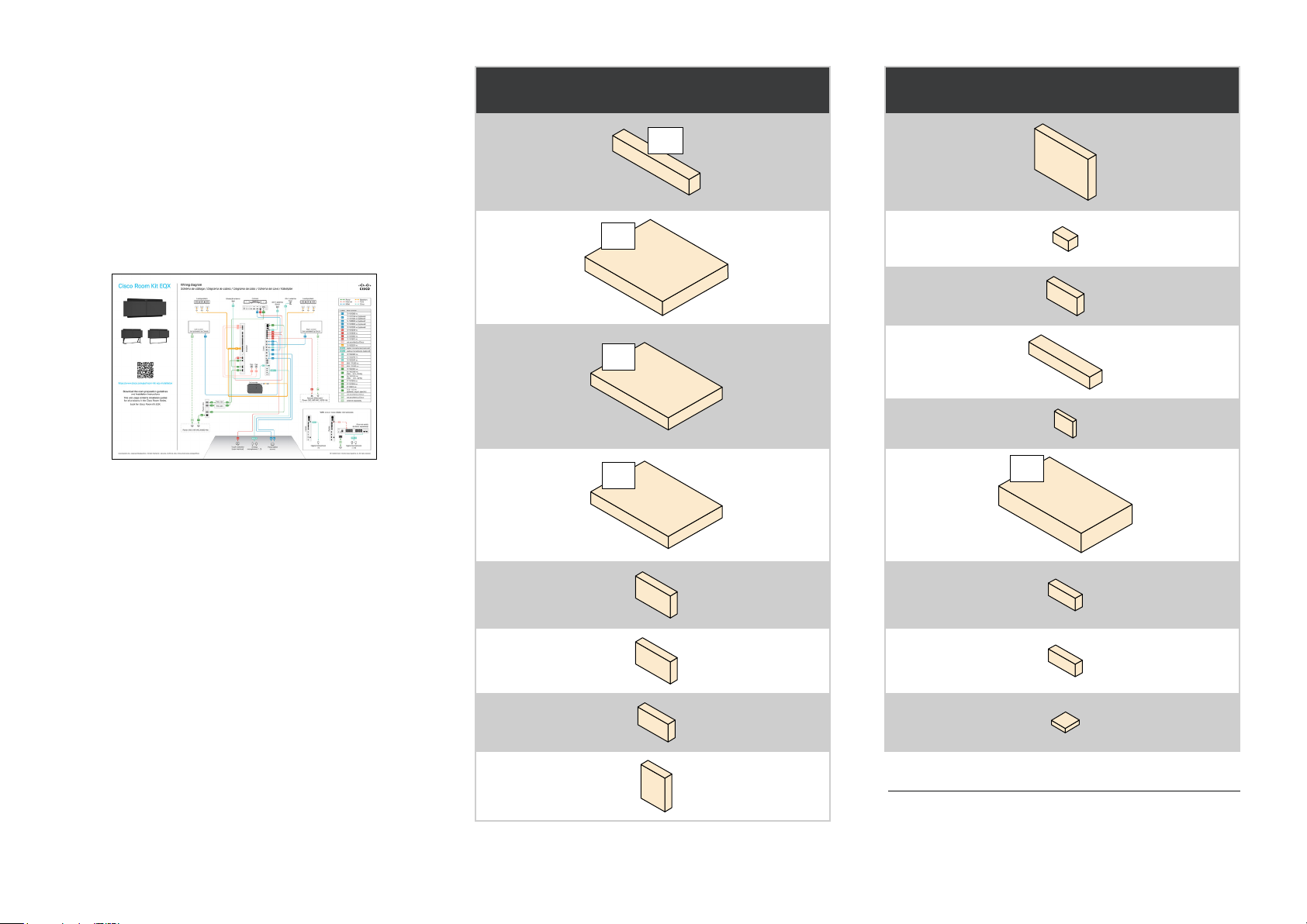
PACKAGING....................................................... 4
SCREWS AND TOOLS........................................ 5
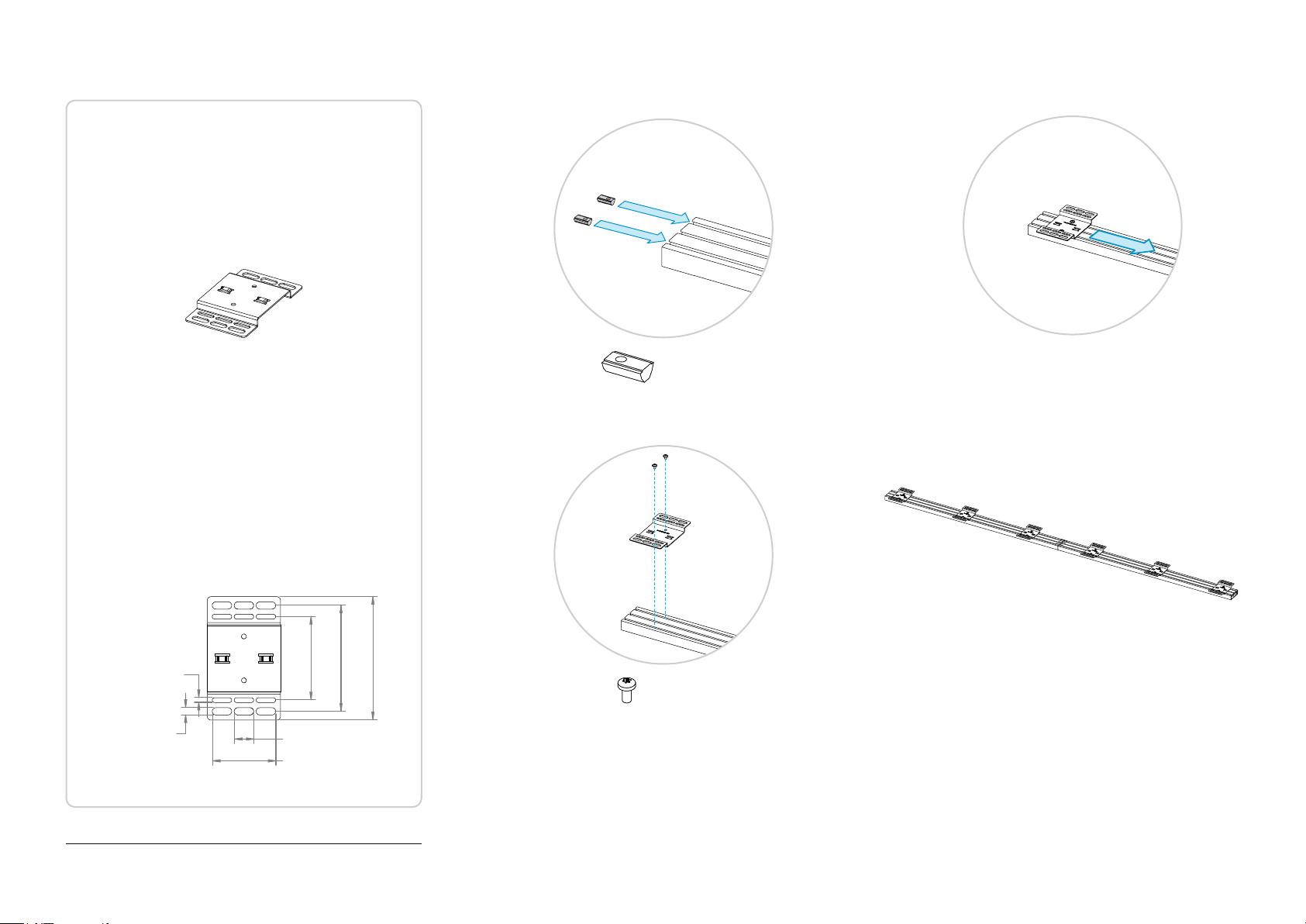
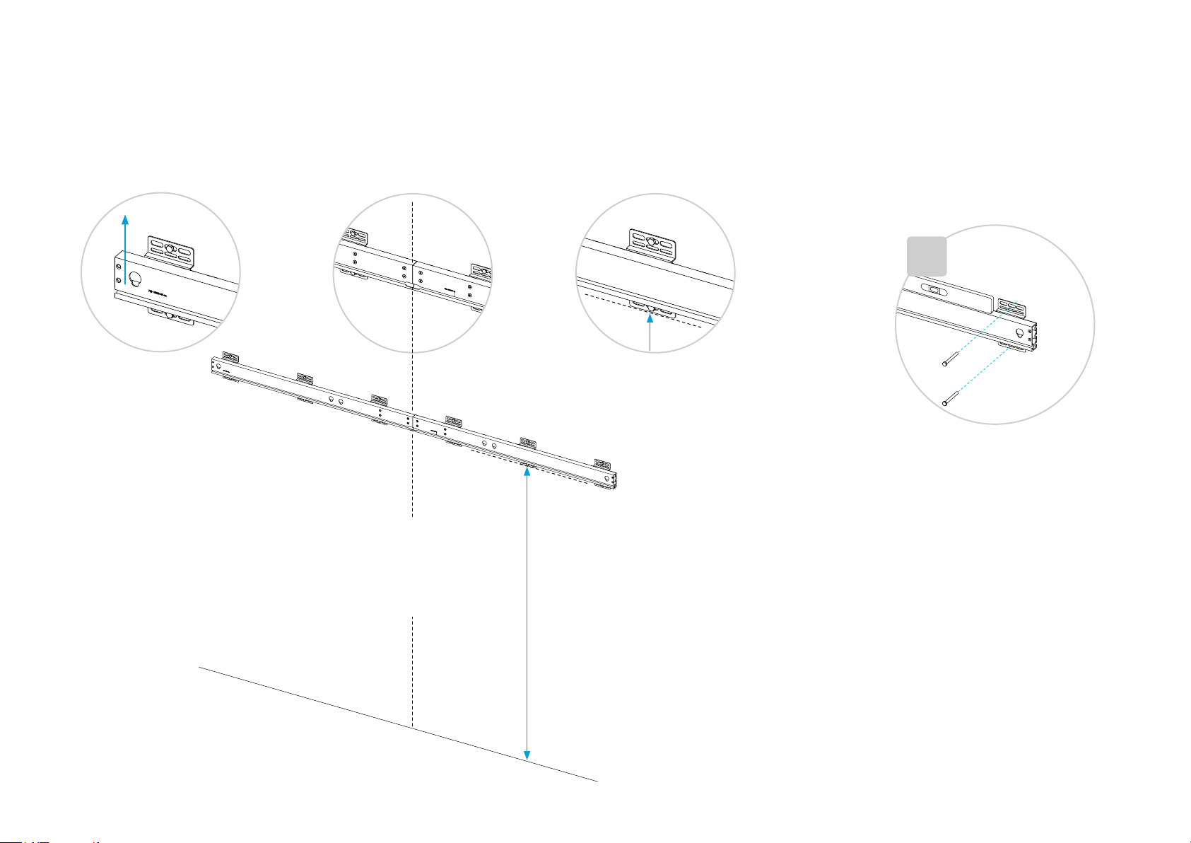
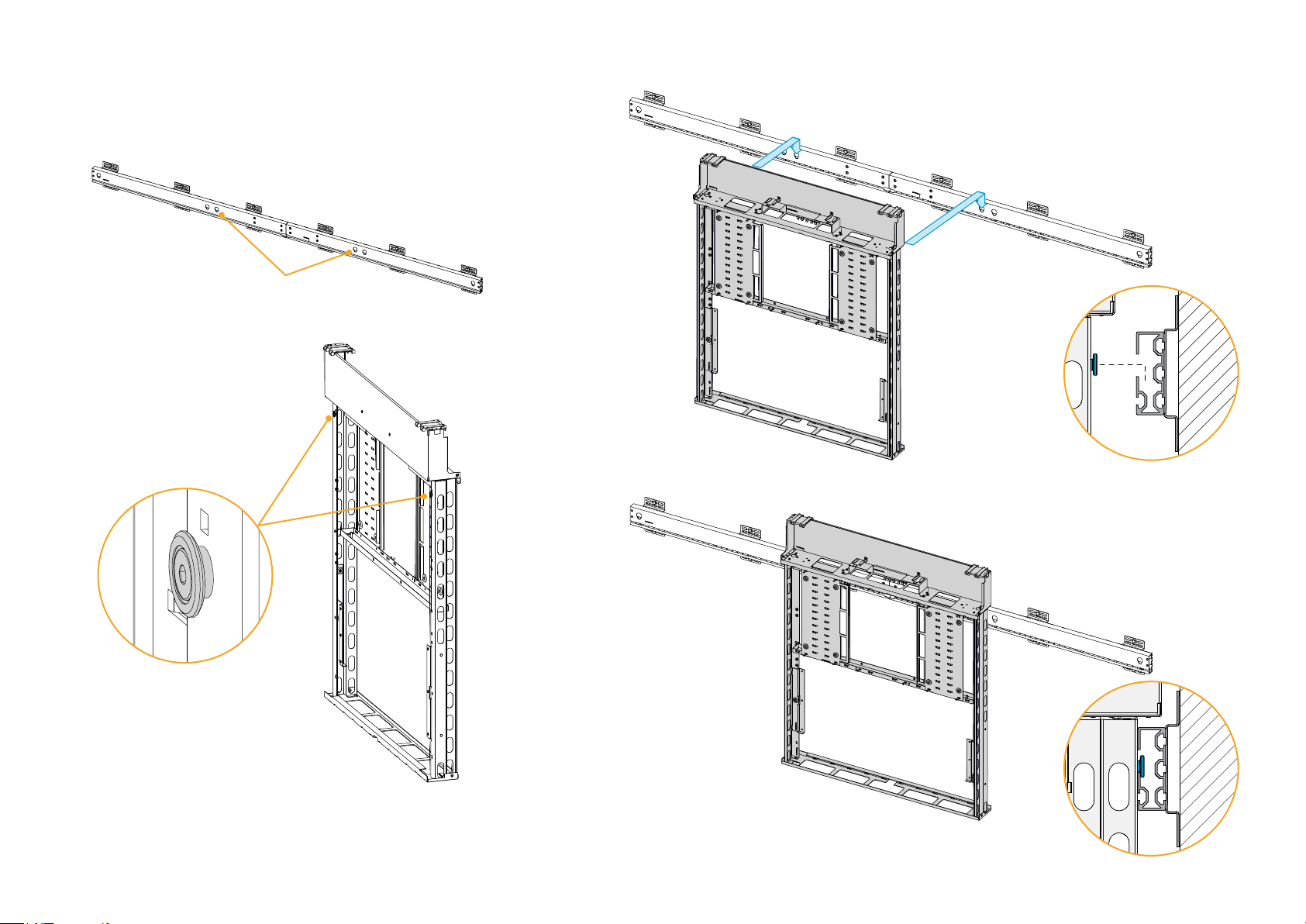
1. Mount the wall mount beam........................... 6
2. Mount the modules ........................................ 9
3. Insert the codec and amplifier ......................14
ABOUT CABLING ..............................................15
4. Mount the power strip and PSUs ..................17
5. Attach the rating label.................................. 20
6. Mount the loudspeakers ...............................21
7. Mount the fan module ...................................24
8. Mount the top brackets.................................27
9. Mount the antenna brackets .........................28
10. Insert the camera ....................................... 30
11. Attach the antennas ................................... 33
12. Connect screen cables ............................. 34
13. Connect power and network cables .......... 35
14. Connect the microphones.......................... 36
15. Connect the Room Navigator and
presentation cables ..........................................37
16. Mount the covers ....................................... 38
17. Mount the speaker grille............................. 39
18. Mount the bottom grille.............................. 44
19. Mount the side panels................................ 48
20. Mount the left screen................................. 49
21. Mount the right screen ............................... 54
22. Fine-adjust the screens ..............................57
23. Finish-up.................................................... 58
BEFORE YOU START THE INSTALLATION
It is important that you read our Room Preparation Guidelines
before you start the installation. They are available online.
During the installation you need both the Installation guide
(this guide) and the Wiring Diagram. The wiring diagram is
shipped with the product.
We recommend you to check if there are newer versions of
the documents online. You find the version number on the
first page (format: 78-xxxxxx-yyyy, where yyyy is the version
number; or Dxxxxx.yy, where yy is the version number).
Download information
You can download the room preparation guidelines, wiring
diagram, and installation guides from:
https://www.cisco.com/go/room-kit-eqx-installation
This webpage contains installation guides for all products in
the Cisco Room Series. Look for Cisco Room Kit EQX.
Installation by instructed personnel
Due to the size and mass of the Room Kit EQX system, it
must be installed according to our installation instructions by
qualified personnel. The installer must determine whether the
wall must be reinforced prior to the installation and calculate
the number and type of screws required for a safe wall
mounting.
The product is fastened to the wall
The Room Kit EQX is fastened to the wall with a horizontal
beam. The beam must be fastened so that it can safely
support the product. The product may weigh up to
220kg (485lb), including screens*.
Perfectly flat wall
The beam must be level. If the wall is not perfectly flat, this
must be compensated for before you mount the beam.
Power
Don’t use an external multi-socket extension cord for the
Cisco components; use the provided power strip.
Temperature
Don’t install the Room Kit EQX where it may be exposed to
direct sunlight.
Only use screens with operating temperature of 40°C
(104°F) or better.
*Maximum weight per screen allowed is 50kg (110lb).

4Copyright © 2023 Cisco Systems, Inc. All rights reserved.D15514.01 | 2023 OCTOBER | Cisco Room Kit EQX Installation Guide
PACKAGING
You have received a pallet with several boxes. Except for
the screens, which are not provided by Cisco, these boxes
include the parts you need to install the wall mount version of
Room Kit EQX.
When installing the system, you start with the mounting kit,
which is in the box marked with A.
You find the complete wiring diagram and some information
about the boxes just below the overpack lid on the pallet.
Additional components required
• Two screens
Refer to the Room preparation guidelines online for
screen requirement details and recommended screens.
• Microphones (only if you have not included Cisco
microphones in your order).
• Ethernet switch (only if you have more then one digital
microphone, such as Cisco Table Microphone Pro)
We recommend the switches covered in the
Configuration of Cisco CBS250, CBS350, and C1200
switches for use with Cisco video collaboration devices
technical paper online.
Boxes on pallet
Reference
used in this
guide
Wall mount kit1
A
A
Center module1
B
B
Side module 11
C
C1
Side module 21
C
C2
Cisco Codec EQ Codec
Cisco DNAM IV
Amplifier Amplifier
Accessory kit 1 Acc 1
Loudspeakers Speakers
Boxes on pallet
Reference
used in this
guide
Bass Bass
Fans Fans
Accessory kit 2 Acc 2
Cisco Quad
Camera Camera
Cisco Room
Navigator Navigator
Grilles1
D
D
Screen bracket 1 Bracket 1
Screen bracket 2 Bracket 2
Cisco Table
Microphone Pro
(optional)2
Table Mic Pro
1The box has a white label, as shown in the illustration, to help finding
the box on the pallet.
2If you have ordered Cisco Table Microphone Pro (maximum 3), they are
shipped in separate boxes on the pallet. If you have ordered the Cisco
Table Microphone (maximum 3), they are shipped in Accessory kit 2.

5Copyright © 2023 Cisco Systems, Inc. All rights reserved.D15514.01 | 2023 OCTOBER | Cisco Room Kit EQX Installation Guide
SCREWS AND TOOLS
In addition:
• The installer must bring the number and type of screws required for a safe wall mounting of
the system (step 1 and step 2).
Recommended tools and equipment
• Stepladder
• Drill
• Torx T20 bit
• Hex 4 mm bit
• Appropriate drill bits for your wall material
• Appropriate wall fasteners/anchors for your wall construction
• Laser level and/or spirit level
• Measuring tape
• Pencil
Screws and spacers
The following screws and spacers are shipped with the product. They are in boxes A, B, D, and
Acc 2, as further detailed in each step throughout this guide.
Tools
The following tools are shipped with the product. You find them in box A.
Hex 4 mm Tor x T20
(M6x12, Hex 4 mm)
8+0+0+0 pcs.
(Plastic washer)
0+0+66+0 pcs.
(M6x8, Hex 4 mm)
12+8+8+0 pcs.
(M4x8, Torx T20)
4+21+0+4 pc s.
(M4x10, Torx T20)
0+12+70+0 pcs.
(Sliding nut)
16+0+0+0 pcs.

6Copyright © 2023 Cisco Systems, Inc. All rights reserved.D15514.01 | 2023 OCTOBER | Cisco Room Kit EQX Installation Guide
1. Mount the wall mount beam
8x
You also need the number and type of screws that
are required for fastening the beam safely to the
wall (these screws are not provided by Cisco).
Beam parts (Box: A)
1x left carrier beam
1.1. Assemble the wall mount beam
Connect the left and right carrier beam parts together using
the joining bracket and 8 screws (M6x12, Hex 4 mm).
12x
1x right carrier beam
1x joining bracket
6x wall mount bracket 12x sliding nut
The wall mounted Room Kit EQX system is mounted on a
beam that is fastened to the wall.
The beam must be level, and accurately centered about the
system’s vertical center line.
(M6x12, Hex 4 mm) (M6x8, Hex 4 mm)
8x

7Copyright © 2023 Cisco Systems, Inc. All rights reserved.D15514.01 | 2023 OCTOBER | Cisco Room Kit EQX Installation Guide
1.2. Add wall mount brackets to the beam
1. Enter one nut in each notch of the wall mount beam.
2x for each bracket
2. Fasten a wall mount bracket loosly to the nuts that you
just slid in with two screws (M6x8, Hex 4 mm); don’t tighten
the screws.
2x for each bracket
3. Slide the bracket on the beam to its correct position.
4. When in the correct position, tighten the two screws.
Repeat steps 1-4 above for all wall brackets.
*Maximum weight allowed per screen is 50kg (110lb).
Read before you continue:
We provide 6 wall mount brackets to hold the
system.
The brackets can slide on the beam so that you can
place them where it suits best, for example where
there are studs in the wall.
You can use the holes that fit best to attach the
bracket to the wall.
The installer must provide screws and fasteners
that suites your type of wall.
The installer must decide the number of wall mount
brackets and where to place them to safely support
the system (weight up to 220 kg (485lb) including
screens*).
• Use at least 4 wall brackets.
• The distance from the outermost bracket to
the end of the beam must not exceed 400 mm
(15.7in.) to ensure good weight distribution on
the beam.
Wall bracket dimensions:
114 mm
(4.5 in)
145 mm
(5.7 in)
169 mm
(6.6 in)
10 mm
(0.4 in)
7 mm
(0.3 in)
27 mm
(1.0 in)
87 mm
(3.4 in)

8Copyright © 2023 Cisco Systems, Inc. All rights reserved.D15514.01 | 2023 OCTOBER | Cisco Room Kit EQX Installation Guide
1. The distance from the floor to the lower edge of the wall
brackets are shown in the illustration.
Check the key holes to avoid placing the beam upside
down.
2. Make sure the beam is level, and fasten all the brackets
to the wall. You can use any of the horizontal slots in the
bracket.
The installer must provide screws and fasteners that
suites your type of wall.
1.3. Fasten the beam to the wall
1.57m (61.8 in.)
Up
System center line
×6

9Copyright © 2023 Cisco Systems, Inc. All rights reserved.D15514.01 | 2023 OCTOBER | Cisco Room Kit EQX Installation Guide
2. Mount the modules
The main mounting structure is composed of three modules
hanging on the wall mount beam; one center module and two
identical side modules.
Mounting modules
2.1. Slide nuts in the wall mount beam
Slide 4 nuts into the notch on the beam. Place the nuts below
the keyholes.
The nuts are required when fastening the modules to the
beam in step 2.4.
4x sliding nut
(Box: A)
×4
8x
You also need two screws for fastening the angle
bracket to the wall (not provided by Cisco).
2x side module
(Box: C1, C2)
1x center module
(Box: B)
2x angle bracket
(Box: A)
(M6x8, Hex 4 mm)
(Box: B)
4x

10 Copyright © 2023 Cisco Systems, Inc. All rights reserved.D15514.01 | 2023 OCTOBER | Cisco Room Kit EQX Installation Guide
2.2. Hang the center module onto the beam
1. Observe the keyholes on the beam, and the large screw heads at
the back of the center module.
2. Hang these screws onto the beam keyholes.
Keyholes for the
center module
Rear view of
center module
Screw with large head,
for hanging the module
on the beam.

11 Copyright © 2023 Cisco Systems, Inc. All rights reserved.D15514.01 | 2023 OCTOBER | Cisco Room Kit EQX Installation Guide
2.3. Hang the side modules onto the beam
Repeat this for both side modules; the side modules are identical.
1. Observe the keyholes on the beam, and the large screw heads at
the back of the side module.
2. Hang these screws onto the beam keyholes.
Keyholes for the
left side module
Keyholes for the
right side module
Rear view of
side module
Screw with large head,
for hanging the module
on the beam.
To avoid getting your fingers pinched between the modules,
lift a side module by holding your hands on the top and bottom
of the module; NOT on the side toward the center module.

12 Copyright © 2023 Cisco Systems, Inc. All rights reserved.D15514.01 | 2023 OCTOBER | Cisco Room Kit EQX Installation Guide
2.4. Fasten the modules to each other and to the beam
×2
×2
2. Fasten the side modules to the beam with 2 screws
(M6x8, Hex 4 mm) each. The screws enter the nuts that you
added in step 2.1.
1. Fasten both side modules to the center module with
2 screws (M6x8, Hex 4 mm) each.
×2
2x
4x
2x
×2

13 Copyright © 2023 Cisco Systems, Inc. All rights reserved.D15514.01 | 2023 OCTOBER | Cisco Room Kit EQX Installation Guide
2.5. Straighten up the frame
1. Adjust the four spacers (thumbscrews) until the frame
is plumb (perfectly straight up and down; no tilt). Use a
spirit level.
×4
2. Fasten the straightened up frame with one bracket
on each side. The installer must provide screws and
fasteners that suites your type of wall.
×2
When tightening the screw the bracket will intentionally
bend a bit, since the spacers (not these brackets)
determine the system’s distance to the wall.
brackets
spacers

14 Copyright © 2023 Cisco Systems, Inc. All rights reserved.D15514.01 | 2023 OCTOBER | Cisco Room Kit EQX Installation Guide
3. Insert the codec and amplifier
The codec and amplifier are placed in the center module, in
bays behind metal clamps.
codec
amplifier
Codec and amplifier
1x codec (Box: Codec)
1x amplifier (Box: Amplifier)
3.1. Insert the codec
1. Loosen the four wing nuts that hold the right metal clamp
in place.
2. Slide the codec fully into the bay behind the clamp.
Connectors facing toward center; power socket up.
3. Slide the metal clamp to the right until it stops against the
codec edge; then tighten the four wing nuts to keep the
codec in place.
3.2. Insert the amplifier
1. If the amplifiers has rack ears, remove them. (Torx T10).
2. Loosen the four wing nuts that holds the left metal clamp
in place.
3. Slide the amplifier fully into the bay behind the clamp.
Connectors facing toward center; fan connectors up.
4. Slide the metal clamp to the left until it stops against the
amplifier edge; then tighten the four wing nuts to keep
the amplifier in place.
Wing
nuts
Wing
nuts
×4 ×4

15 Copyright © 2023 Cisco Systems, Inc. All rights reserved.D15514.01 | 2023 OCTOBER | Cisco Room Kit EQX Installation Guide
Wiring diagram
A full wiring diagram is shipped with the product. It is also
available online, at https://www.cisco.com/go/room-kit-eqx-
installation
The wiring diagram also gives some guidance how to route
the cables.
Cable marking
Each cable has a part number, which is printed on the cable.
The installation guide and wiring diagram refer to cables by a
label, for easy reference.
You’ll find a table that maps the label to a part number in the
wiring diagram.
Where are the cables
The cables are in the accessory kit boxes (Box: Acc 1, Acc 2).
Cable routing
The colored areas in this illustration show the main areas for
cable routing. See more details on the next page.
In each step, we show the recommended route for that
specific cable; without explicitly showing which hole to
thread each and every cable through.
Organize cables neatly using velcro
We strongly recommend that you fasten the cables to the
steel structure with velcro straps (Box: B). This is to avoid
strain on cables and connectors, to avoid rattling noise, and
for a neat and tidy look.
The steel structure is equipped with many fastening points
for velcro straps.
The 3 nylon cable ties (Box: B) are for securing the camera
cables in step 10.3.
ABOUT CABLING
In the next mounting step you start connecting cables.
Here are some important notes for a correct, nice, and tidy
cabling.
Do not connect to power yet!
Do not connect any power cables to wall socket outlets
before step “23. Finish-up” on page 58.

16 Copyright © 2023 Cisco Systems, Inc. All rights reserved.D15514.01 | 2023 OCTOBER | Cisco Room Kit EQX Installation Guide
The bottom trays. Keep
the cables away from
the bass to avoid rattling
noise. Use the supplied
velcro straps.
The channels between
the modules. Also the
channels on the sides can
be used, if convenient for
the socket outlet location
in your room.
Thread cables through the
holes where convenient.
Behind the flap - from
the channels and through
the holes for the camera
and loudspeakers. Keep
the cables away from the
loudspeakers to avoid
rattling noise. Use the
supplied velcro straps.
The main cable routing areas
In front of the codec
and amplifier clamps.
All cables for the codec/
amplifier comes from the
channels between the
modules.
Lead the cables out
through one of the holes,
across the clamp, and
then back again to the
connector panels. This is
important for strain relief.
When done, fasten the
cables with velcro.
A few cables also run
across from left to right
just below the clamps.
Keep the cables away from
the bass to avoid rattling
noise. Use the supplied
velcro straps.

17 Copyright © 2023 Cisco Systems, Inc. All rights reserved.D15514.01 | 2023 OCTOBER | Cisco Room Kit EQX Installation Guide
4. Mount the power strip and PSUs
Power strip and PSUs (Box: B)
1x Power strip
The power strip and PSUs are placed in the left side module,
close to the bottom.
Don’t connect the power strip to the wall socket outlet now.
1x Power strip bracket
1x PSU, 12 V 1x PSU bracket
1x PSU, 24V
4.1. Mount the power strip
Place the bracket over the power strip and fasten it to the
back plate with three screws (M4x8, Torx T20).
4.2. Mount the PSUs
1. Fasten the PSU bracket to the back plate with four
screws (M4x8, Torx T20).
2. Slide the two PSUs into the bracket. The smaller 12V
PSU is above the larger 24 V PSU.
The cables that are fixed to the PSUs are to the right.
7x
(M4x8, Torx T20)
3x 4x
To wall socket outlet (in step 23)
From codec (in step 4.4)
Not in use (intentionally blocked by bracket)
From 12 V PSU (in step 4.3)
From 24V PSU (in step 4.3)
Downward

18 Copyright © 2023 Cisco Systems, Inc. All rights reserved.D15514.01 | 2023 OCTOBER | Cisco Room Kit EQX Installation Guide
4.3. Connect the PSU cables
1. Connect the PSUs to the power strip:
• D4 for the 24V PSU
• D5 for the 12 V PSU
D4
D5
2. The 24V PSU (the largest one) has a power switch.
Switch it to ON.
3. Guide the cables as shown in the illustration, and connect
the PSUs to the amplifier:
• D2 for the 24V PSU
• D3 for the 12 V PSU
Coil and strap (with velcro) excess cable close to the
PSUs, see illustration.
Amplifier
To 24V PSU
D3
D2
To 12V PSU
D3
D2
D3
D2
D3
D2

19 Copyright © 2023 Cisco Systems, Inc. All rights reserved.D15514.01 | 2023 OCTOBER | Cisco Room Kit EQX Installation Guide
4.4. Connect the codec power cable
Connect the power cable between the codec and the
power strip, E2.
Codec
C
To power strip
E2
E2
E2

20 Copyright © 2023 Cisco Systems, Inc. All rights reserved.D15514.01 | 2023 OCTOBER | Cisco Room Kit EQX Installation Guide
5. Attach the rating label
Rating label (Box: Acc 1)
1x rating label
Attach the self-adhesive rating label here.
The label shows that the Room Kit EQX system
complies with country compliance regulations.
Productname (品名 / Nom du Produit):
CiscoRoom Kit EQX 视频会议系统
Model(型号/Modèle): TTC60-34
Manufacturer(制造商/Fabricant): Cisco Systems, Inc.,
170West Tasman Drive, San Jose, CA 95134, USA
PowerInput (输入/Entrée):
3.0-1.5A100-240V~ 50-60Hz
Designedby Cisco (思科研发/Conçu par Cisco)
www.cisco.com
IncludesCisco Codec Model TTC6-15, IFETEL certicate RCPCXXXXX-XXXX-XX
IncluyeCódec (Sistema de videoconferencia) Cisco modelo TTC6-15,
certicado del IFETEL RCPCXXXXX-XXXX-XX
ContainsFCC ID: LD K0615C2718
Contains/ContentIC: 2461N-0615C2718
CMIITID: X-YYYYY
CANICES-3(A)/NMB-3(A)
E-503R-NZ
56-107769-XX-XX
S/N:
PID:
MAC:See Rating Label on Cisco Codec EQ
Thisdevice complies with Part 15 of the FCC Rules. Operation is
subjectto the following two conditions: (1) this device may not cause
harmfulinterference, and (2) this device must accept any interference
received,including interference that may cause undesired operation.
Mfg.Site: ShenZhen Fulian FuGui Precision Industry Co., Ltd
Madein China /
中国制造
/ Fabriqué en Chine
Mfg.Date / Date de fabrication: YYYYMMMDD
Apparatetmå tilkoples jordet stikkontakt. Apparaten skall anslutas till jordat uttag.
Laiteon liitettävä suojakoskettimilla varustettuun pistorasiaan.
Apparatetsstikprop skal tilsluttes en stikkontakt med jord, som giver forbindelse
tilstikproppens jord.
此设备需要接地
S/N:XXXXXXXXXXX
PID:CS-KIT-EQX-XXX
Complies with
IMDA standards
DB101992
AAAAA-BB-CCCCC
PTCxxx / xx / xxx
Telepermitholder:
CiscoSystems(NZ) Ltd
Model:TTC60-34. Product:
CiscoRoomKitEQX
VideoConferencingSystem
62368-1
XXXXX-YYYYYY 모니터
R-R-TNY-TTC60-34
MSIP-xxxxx-xxxxx-Pxxxx
INDIA
CERTIFICATENO.-
TECXXXXXXXX
Product name (品名 / Nom du Produit):
Cisco Room Kit EQX 视频会议系统
Model (型号/Modèle): TTC60-34
Manufacturer (制造商/Fabricant): Cisco Systems, Inc.,
170 West Tasman Drive, San Jose, CA 95134,USA
Power Input (输入/Entrée):
3.0-1.5A 100-240V~ 50-60Hz
Designed by Cisco (思科研发/Conçu par Cisco)
www.cisco.com
Includes Cisco Codec Model TTC6-15, IFETEL certicate RCPCXXXXX-XXXX-XX
Incluye Códec (Sistema de videoconferencia) Cisco modelo TTC6-15,
certicado del IFETEL RCPCXXXXX-XXXX-XX
Contains FCC ID: L DK0615C2 718
Contains/Content IC: 2461N-0615C2718
CMIIT ID: X-YYYYY
CAN ICES-3(A)/NMB-3(A)
E-503 R-NZ
56-107769-XX-XX
S/N:
PID:
MAC: See Rating Label on Cisco Codec EQ
This device complies with Part 15 of the FCC Rules. Operation is
subject to the following two conditions: (1)this device may not cause
harmful interference, and (2) this device must accept any interference
received, including interference that may cause undesired operation.
Mfg. Site: ShenZhen Fulian FuGui Precision Industry Co., Ltd
Made in China /
中国制造
/ Fabriqué en Chine
Mfg. Date / Date de fabrication: YYYYMMMDD
Apparatet må tilkoples jordet stikkontakt.Apparaten skall anslutas till jordat uttag.
Laite on liitettävä suojakoskettimilla varustettuun pistorasiaan.
Apparatets stikprop skal tilsluttes en stikkontakt med jord, som giver forbindelse
til stikproppens jord. 此设备需要接地
S/N: XXXXXXXXXXX
PID: CS-KIT-EQX-XXX
Complies with
IMDA standards
DB101992
AAAAA-BB-CCCCC PTC xxx / xx / xxx
Telepermitholder:
CiscoSystems (NZ) Ltd
Model: TTC60-34. Product:
CiscoRoomKit EQX
VideoConferencing System
62368-1
XXXXX-YYYYYY 모니터
R-R-TNY-TTC60-34
MSIP-xxxxx-xxxxx-Pxxxx
INDIA
CERTIFICATENO. -
TECXXXXXXXX
This manual suits for next models
1
Table of contents