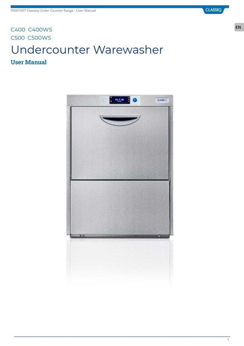
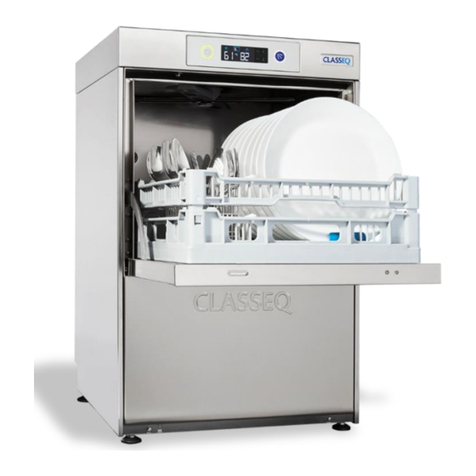
Classeq P500 Quick start guide

P500 P500-A P500-A-WS P500-AS P500-AS-WS
Pass Through Warewasher
(YR2020 WK11)
Engineers Manual

Classeq Pass Through Range - User Manual
2
Dear User,
This engineer’s manual is for the Classeq Pass-through Warewasher range. It is intended to provide all the essential information required to
diagnose any faults that may occur throughout the life of this product. This manual includes a description and diagram of the different
systems available within the Pass Through range, information on the functions and capabilities, contingencies and alternate modes of
operation, and step by step procedures for system access and use.

Classeq Pass Through Range - User Manual
3
TABLE OF CONTENT
1. INTRODUCTION 4
1.1 Installation and commissioning 4
1.2 Service and repairs 4
1.3 Modification 4
2. SAFETY 4
2.1 Symbols Used in this Manual 4
2.2 Danger Warnings 4
2.3 Warnings 4
2.4 Cautions 4
3. TOOLS LIST 4
4. WATER SYSTEM 5
4.1 Water ways 5
4.2 Water ways legend 5
4.3 P500 (Pressurised) 6
4.4 P500-A (Standard Air-break) 6
4.5 P500-A-WS (Standard Water Softener) 7
4.6 P500-AS (AS Air Break) 7
4.7 P500-AS-WS (AS Water Softener) 8
4.8 Water Softener Unit 8
5. MACHINE SPECIFICATIONS 9
5.1 Systems matrix 9
5.2 Mechanical specifications/ site requirements 9
5.3 Electrical Components Specification 9
5.4 Pump wiring 10
5.5 External Chemical Pump Signals 10
5.6 Terminal Block Layout 11
5.7 Terminal Block Configurations 11
5.8 Contactor Wiring 12
6. LOGIC 14
6.1 Indicator Logic 14
6.2 Fill and Heat 14
6.3 Wash and Rinse 15
6.4 Drain 15
6.5 Chemical Dosing 15
6.6 Water Softener Unit 16
7. COMMISSIONING 17
7.1 Commissioning/ Service Interface 17
7.2 Commissioning Mode 17
7.3 Setting Chemical Dosage 17
7.4Priming Chemicals 17
7.5 Setting Water Hardness (if fitted) 17
8. SERVICE MODE 19
8.1 Accessing Service Mode 19
8.2 Program Value 19
8.3 Heat Interlock Settings 19
8.4 Reset to Factory Settings 20
8.5 Statistics 20
8.6 Loads 20
8.7 Errors 21
9. CONTROL UNIT 23
9.1 Inputs and Outputs 23
9.2 Board Setup 24
10. WASH PERFORMANCE 25
10.1 Recommended chemicals 25
10.2 Recommended chemical dosing 25
10.3 Recommended Temperatures 25
10.4 Troubleshooting 25
11. CABLE REPAIR KITS 27
11.1 Available Cable Kits List 27
27
11.2 Cable Kit Information 27
11.3 Cable Kit Diagram 27
12. QUICK REFERENCE 28
13. MACHINE RATING 29
13.1 Element Ratings 29
13.2 Mains Cable Types 29
13.3 Mains Cable Specification 29
14. WIRING DIAGRAMS 30
14.1 Std 30
14.2 AS 31
14.3 No Neutral 32
15. USEFUL CONTACT DETAILS 33
16. NOTES 34

Classeq Pass Through Range - Engineers Manual
4
1. Introduction
Prior to reading this manual it is essential that you are familiar
with the contents and subject matter covered by the “Installation
and Operation manual”.
1.1 Installation and commissioning
Installation and commissioning instructions are detailed in the
“Installation and Operation manual” and should always be
followed. Incorrect installation may invalidate any warranties.
1.2 Service and repairs
Repairs to the machine should only be carried out by a Classeq
approved/trained technician using genuine Classeq parts. Failure
to do so may invalidate any warranties.
1.3 Modification
Classeq reserves the right to modify the machine or the contents
of this manual without notice.
2. Safety
2.1 Symbols Used in this Manual
The following symbols are used in this Manual:
DANGER!
Warning against potential serious or fatal
injuries to persons if the described
precautionary measures are not taken.
Warning!
Warning against potential minor injuries to
persons or potential material damage if the
described precautionary measures are not
taken.
Caution
Warning against defects in or destruction of
the product if the described precautionary
measures are not taken.
Recycling instructions.
►
This symbol refers to a chapter with more
detailed information
2.2 Danger Warnings
Unless the machine has been isolated from the supply
there will always be potential for mains voltage to any
components in the machine.
2.3 Warnings
DO NOT run the machine if there is no salt in the salt
reservoir, as this will allow lime scale to build up, also any
lime scale will invalidate your warranty.
DO NOT add any chemicals, such as detergent or rinse
aid to the reservoir. These will cause damage to the
machine.
2.4 Cautions
Only use granulated salt (max. grain size 5 –7 mm). Salt
tablets are not suitable.
If the reservoir cap is not properly secured, water and/or
chemicals can leak in or out of the unit causing damage
to the machine.
Repairs to the machine should only be done with the
mains supply isolated.
Any changes made to P30 will not be saved if power to the
machine is disrupted before completely exiting service
mode.
3. Tools List
The below list of tools will allow access to all components within
the machine:
Tool group
Description
Spanner/nut runner/ratchet
5.5mm
7mm
8mm
13mm
Hex key
2mm
3mm
4mm
Posi screw driver
No. 2
No. 3
Electrical testing
Ammeter (A)
Capacitance meter (µF)
Resistance meter (Ω)
Continuity ()

Classeq Pass Through Range - Engineers Manual
5
4. Water System
4.1 Water ways
Detailed within this section are the water ways and system details
for each of the Pass Through Warewashers.
Models
Description
P500
Pressurised System
P500-A
Standard Air Break System
P500-A-WS
Standard Water Softener System
P500-AS
AS Air Break System
P500-AS-WS
AS Water Softener System
4.2 Water ways legend
Key
Description
ISV
Inlet solenoid valve
LCV
Lateral check valve
AB
WRAS approved type AB air gap
RB
Rinse tank
RBP
Rinse booster pump
WP
Wash pump
DP
Drain pump
RA
Rinse arm
WA
Wash arm
WSU
Water softener unit
NRV
Non-return valve
ASU
Anti-syphon unit
SR
Salt reservoir
Res
Resin chamber
Solenoid valve
Paddle sensor
Ball valve
Air gap
Switching valve
Non return ball valve
BU
Incoming water
GR
Softened water
R
Rinse water
O
Wash water
GY
Waste water –Pumped drain
GY
Waste water –Gravity drain
P
Waste water –Water softener
O
Breather

Classeq Pass Through Range - Engineers Manual
6
4.3 P500 (Pressurised)
P500-A (Standard Air Break)
4.4 P500-A (Standard Air-break)

Classeq Pass Through Range - Engineers Manual
7
4.5 P500-A-WS (Standard Water Softener)
4.6 P500-AS (AS Air Break)

Classeq Pass Through Range - Engineers Manual
8
4.7 P500-AS-WS (AS Water Softener)
4.8 Water Softener Unit

Classeq Pass Through Range - Engineers Manual
9
5. Machine
Specifications
5.1 Systems matrix
Below is a table describing the various electrical arrangements
available for the different machine types.
Type
30A 1N~
12A 3N~
16A 3N~
22A 3N~
17A *3~
P500
●
◐
◐
○
●
P500 A
●
◐
◐
○
◐
P500 AS
○
○
○
●
○
●- Standard
◐- Optional
○–Not available
5.2 Mechanical specifications/ site requirements
For details on machine dimensions and site requirements refer
to the “Installation and Operation manual” for the machine.
5.3 Electrical Components Specification
The table below indicates the electrical components in the
machines and their electrical specifications
Below is a table describing the various system specifications
available for the different machine types.
Type
Rinse
pump
WRAS
approved
air gap
Inbuilt
Water
softener
Drain
pump
P500
○
○
○
●
P500 A
●
●
◐
●
P500 AS
●
●
◐
●
Component
Voltage range
(V)
Frequency (Hz)
Current (A)
Power (W)
Resistance (Ω)
Inlet solenoid
220-240
50/60
0.026
6
4110
Rinse element
6000
220-240
50/60
8.68 /leg
20.09 Total
3 x 2000
27.5 / leg
8640
12.52 / leg
37.57 Total
3 x 2880
21 / leg
Rinse pump
220-240
50
0.7
190
M –32.2
A –43.3
220-240
60
0.66
146
M –26.78
A –34.8
Wash element
220-240
50/60
5.87 /leg
4000
39.18 / leg
Wash pump
220-240
50
2.55
580
M –9.52
A –18.97
220-240
60
2.42
550
M –8.06
A –16.11
Drain pump
220-240
50
0.2
30
145.1
208-240
60
0.15
32
76
Contactors
220-240
50/60
0.27
60
n/a
Detergent pump
220-240
50/60
0.03
8
3180
Rinse aid pump
220-240
50/60
0.03
8
3180

Classeq Pass Through Range - Engineers Manual
10
5.4 Pump wiring
5.4.1 Windings
The windings of the wash and rinse pumps are wired to the plug
as below:
Winding legend
Key
Description
M
Main winding
A
Auxiliary winding
PE
Earth wire (Green and Yellow)
BU
Blue wire
BK
Black wire
5.4.2 Rinse Pump Connector
5.4.3 Wash Pump Connector
5.5 External Chemical Pump Signals
The external chemical signals terminal block is located on the
centre rail next to the heating contactors inside the machine.
The signals provided are triggered by the dosing rates set in the
‘Commissioning Menu’ (►7.3). The dosing rates stated in the Menu
may differ depending on the pump flow rate.
BLUE - Neutral
BLUE –Rinse Aid Pump
WHITE –Detergent Pump
GREEN/ YELLOW - Earth
Violet
Violet
Blue
Blue
Green/
Yellow
Empty
Blue
Blue
Brown
Black
Green/
Yellow
Empty

Classeq Pass Through Range - Engineers Manual
11
5.6 Terminal Block Layout
5.6.1 P500, P500-A & P500-A-WS
5.6.2 P500-AS & P500-AS-WS
5.6.3 P500, P500-A & P500-A-WS (No Neutral)
5.7 Terminal Block Configurations
5.7.1 1Phase 30Amp
5.7.2 3Phase 12Amp / 16Amp
5.7.3 3Phase 22Amp
5.7.4 3Phase 17Amp (No Neutral)
L1
L2
L3
N

Classeq Pass Through Range - Engineers Manual
12
5.8 Contactor Wiring
The contactors on the both heating elements are labelled as
below;
5.8.1 P500, P500-A & P500-A-WS
Wash Contactor
Position
1
3
5
13
A
Wire
Colour
2x
Brown
1x
Black
2x
Blue
None
1x
Black
Crimp
Colour
2x
Blue
1x
Blue
2x
Blue
None
1x
White
Position
2
4
6
14
B
Crimp
Colour
1x
Blue
1x
Blue
2x
Blue
None
1x
White
Wire
Colour
1x
Brown
1x
Black
2x
Blue
None
1x
Black
Rinse Contactor
Position
1
3
5
13
A
Wire
Colour
2x
Brown
2x
Black
2x
Grey
None
1x
Purple
Crimp
Colour
2x
Grey
2x
Grey
2x
Grey
None
1x
White
Position
2
4
6
14
B
Crimp
Colour
1x
Grey
1x
Grey
1x Grey
None
1x
White
Wire
Colour
1x
Brown
1x
Black
1x Grey
None
1x
Purple

Classeq Pass Through Range - Engineers Manual
13
5.8.2 P500-AS & P500-AS-WS
Wash Contactor
Position
1
3
5
13
A
Wire
Colour
2x
Brown
1x
Black
2x
Blue
2x
Blue
1x
Black
Crimp
Colour
2x
Blue
1x
Blue
2x
Blue
2x
Blue
1x
White
Position
2
4
6
14
B
Crimp
Colour
1x
Blue
1x
Blue
1x
Blue
None
1x
White
Wire
Colour
1x
Brown
1x
Black
1x
Grey
None
1x
Black
Rinse Contactor
Position
1
3
5
13
A
Wire
Colour
2x
Brown
2x
Black
2x
Grey
2x
Blue
1x
Purple
Crimp
Colour
2x
Grey
2x
Grey
2x
Grey
2x
Grey
1x
White
Position
2
4
6
14
B
Crimp
Colour
2x
Grey
2x
Grey
2x
Grey
None
1x
White
Wire
Colour
2x
Brown
2x
Black
2x
Grey
None
1x
Purple
5.8.3 P500,P500-A & P500-A-WS (No Neutral)
Wash Contactor
Position
1
3
5
13
A
Wire
Colour
2x
Brown
1x
Black
1x Grey
1x Blue
None
1x
Black
Crimp
Colour
2x
Blue
1x
Blue
2x
Blue
None
1x
White
Position
2
4
6
14
B
Crimp
Colour
1x
Blue
1x
Blue
1x
Blue
None
1x
White
Wire
Colour
1x
Brown
1x
Black
1x
Grey
None
1x
Black
Rinse Contactor
Position
1
3
5
13
A
Wire
Colour
1x
Brown
1x
Black
1x
Grey
None
1x
Purple
Crimp
Colour
1x
Grey
1x
Grey
1x
Grey
None
1x
White
Position
2
4
6
14
B
Crimp
Colour
1x
Grey
1x
Grey
1x
Grey
None
1x
White
Wire
Colour
1x
Brown
1x
Black
1x
Grey
None
1x
Purple

Classeq Pass Through Range - Engineers Manual
14
6. Logic
6.1 Indicator Logic
Item
Description
1
Heating indicator
2
Cycle indicator
6.1.1 Heating Indicator
This will illuminate GREEN only when following condition is
achieved:
•Wash tank water level full
•Rinse tank water level full
Refer (►8.2) for more options.
If one of these has not been achieved the indicator will flash
AMBER to indicate that the machine has not achieved these.
6.1.2 Cycle Indicator
This will illuminate BLUE when a cycle has been requested. The
cycle will then start when the above interlock requirements have
been achieved. This will also flash BLUE during the drain process.
In certain serious error conditions (►8.5) this indicator will
illuminate RED and the machine will turn off.
6.2 Fill and Heat
6.2.1 Pressurized Fill and Heat
Pressurised machines fill and rinse using the solenoid valve and
site water pressure. These machines will fill in the following
manner:
1) Activate solenoid valve until the wash air pressure
sensor reads a minimum level.
2) Heat the rinse tank to a specified transfer temperature;
this is lower than the rinse temperature to ensure that
the wash tank is not too hot after the fill cycle.
3) Activate the solenoid valve to transfer water through
the rinse tank to the wash tank for a specified time.
4) Repeat steps 1 to 3 until the wash tank is full.
5) Once wash tank water level is achieved, GREEN lamp
should illuminate.
6) In the background machine will continue to heat until
the rinse boiler and wash tank have both reached the
specified temperatures.
The following flow diagram shows a representation of this.
6.2.2 Unpressurized Fill and Heat
Unpressurised (air gap) machines fill and rinse using a rinse
booster pump; this means that the rinse is not reliant on the
incoming water pressure. These machines fill in the following
manner:
1) Activate solenoid valve to fill rinse tank.
2) When rinse tank has reached the minimum level it will
start to heat to a specified transfer temperature; this is
lower than the rinse temperature to ensure that the
wash tank is not too hot after the fill cycle.
3) Activate the rinse booster pump to transfer water for a
specified time.
4) Repeat steps 1 to 3 until the wash tank is full.
5) Once the wash tank has reached a minimum level this
will begin to heat if required while the rinse tank is
refilling.
6) On machines with water softeners fitted the machine
will calculate the volume of water that has passed
through the unit and activate the regeneration process
as required.
7) Once wash tank water level and Rinse tank water level
is achieved, GREEN lamp will illuminate.
8) In the background machine will continue to heat until
the rinse boiler and wash tank have both reached the
specified temperatures.
Below is a flow diagram to represent this.
1
2

Classeq Pass Through Range - Engineers Manual
15
6.3 Wash and Rinse
If a cycle is requested when the machine is in standby the wash
and rinse, process on all machines, follow the below procedure:
1) BLUE lamp is Illuminate on cycle indicator.
2) Starts the wash cycle with wash pump activated. Soft
start runs for first 6 seconds.
3) Once the wash tank and rinse tank has achieved the
interlock temperature (P41&P51) and the wash time has
elapsed, Wash pump will be deactivated. If the interlock
temperature are not satisfied during wash cycle time
than it will extend the wash cycle till it has achieved it.
4) There is a pause of 8 seconds to allow the wash tank
water to drip down back in wash tank.
5) Completes the rinse cycle for the specified time (P60)
with activation and deactivation of Rinse pump.
6) There is a short pause after the rinse to allow water to
drip down then the Cycle indicator will turn off.
Below is a flow diagram to represent this.
Refer (►8.1) & (►8.2) for more information on Parameters P41
& P51 and interlock options. Please note if condition for either P41
or P51 not met during specific wash cycle time than it will extend
the wash cycle time till it satisfies the conditions.
6.4 Drain
The drain of the machine functions in two ways:
1. It monitors the water level in the wash tank and drains
away any excess water at any time.
2. If the machine is turned off and the drain cycle is
selected, this function will follow the below process:
a. Start draining the machine. BLUE lamp
flashes to indicate drain cycle.
b. Once the water reaches the minimum level in
the wash tank an “Assisted clean” function will
transfer water from the rinse boiler in the
same fashion as it fills while continuing to
drain (If the door is open at this time the
“Assisted clean” will be cancelled).
c. Once the wash tank reaches a minimum level
again it activates a timer to drain out the
remaining water.
Drain flow diagram to represent this.
6.5 Chemical Dosing
The machine doses chemical at two different stages:
1. While filling the machine:
a. The detergent is dosed into the wash tank
with each transfer. At the end of the fill the
rinse aid is dosed into the rinse tank.
2. While cycling the machine:
a. When a cycle is selected the detergent will
dose into the wash tank. This will not occur on
the first cycle after filling the machine.
b. After each cycle the rinse aid is dosed into the
rinse boiler for the amount of water used.

Classeq Pass Through Range - Engineers Manual
16
6.6 Water Softener Unit
On machines with the integral water softener fitted the machine
will monitor the amount of water passing through the resin of the
softener unit and regenerate at intervals required by the water
hardness setting.
The regeneration process passes salt water into the resin, allows
a contact period for the salt to ‘scrub’ the resin then flushes this
salt water out the waste.
Re-fill salt indicator will flash to indicate water softener
needs salt re-filling. For Salt specification and unit installation
refer to operation manual for more information.
Below is the timing for this function of the water softener unit.
Function
Rinse
until resin
exhausted
Pause
Salt to
resin
Pause
Pressurise
Regen
(Contact)
Pause
Flush
Pause
Time
3s
25s
3s
1.5s
20s
3s
20s
3s
ISV (O8)
WS salt
valve
(O11)
WS
waste
valve
(O12)

Classeq Pass Through Range - Engineers Manual
17
7. Commissioning
7.1 Commissioning/ Service Interface
Item
Description
1
Exit button
2
Enter button
3
Cycle indicator
4
Display
5
Up button
6
Down button
7.2 Commissioning Mode
With the machine turned on at the mains electrical supply but off
at the display, press and hold the Exit (1) and Enter (2) buttons for
3sec. the DISPLAY (4) will show the first menu item and the cycle
indicator (3) will illuminate red.
If no buttons have been pressed for a period of time the machine
will cancel this mode and return to the off state.
Below is the complete menu list.
Display
Description
Units
r**
Rinse aid setting (e.g. 15 = 1.5ml/L)
0.1 x ml/L
rP0
Rinse aid prime
0 = Off
1 = On
d**
Detergent setting (e.g. 33 = 3.3ml/L)
0.1 x ml/L
dP0
Detergent prime
0 = Off
1 = On
h**
Water softener setting (if fitted)
°dH
** Refers to the setting of the chemical dosing. For example the
default setting for rinse aid is 0.5ml of chemical per litre of water
this will be displayed as ‘r05’the default setting for detergent is
3ml of chemical per litre of water this will be displayed as ‘d30’
7.3 Setting Chemical Dosage
1. Enter commissioning mode (►7.2).
2. Using the UP and DOWN keys (5& 6), scroll to the rinse
aid setting menu item (r**) and press ENTER (2).
3. The display will flash.
4. Use the UP and DOWN keys (5& 6) to scroll to the
required setting and press ENTER (2).
5. Using the UP and DOWN keys (5& 6), scroll to the
detergent setting menu item (d**) and press ENTER (2).
6. The display will flash.
7. Use the UP and DOWN keys (5& 6) to scroll to the
required setting and press ENTER (2).
8. Press EXIT (1) until you are out of commissioning mode.
7.4 Priming Chemicals
Before the machine can be used the chemical tubes will need to
be filled with chemicals, in order to do this you will need to follow
the below instructions to prime the chemical pumps.
1. Enter commissioning mode (►7.2).
2. Using the UP and DOWN keys (5& 6), scroll to the rinse
aid prime menu item (rP0) and press ENTER (2)
3. The display will flash and will change to rP1.
4. This will continually run the rinse aid pump for a
maximum of 12 minutes and draw chemicals into the
machine. When the chemicals have reached the back of
the machine press ENTER (2) again to stop the pump.
5. The display will stop flashing and return to rP0.
6. Using the UP and DOWN keys (5& 6), scroll to the
detergent prime menu item (dP0) and press ENTER (2)
7. The display will flash and will change to dP1.
8. This will continually run the detergent pump for a
maximum of 2 minutes and draw chemicals into the
machine. When the chemicals have reached the back of
the machine press ENTER (2) again to stop the pump.
9. The display will stop flashing and return to dP0.
10. Press EXIT (1) until you are out of commissioning mode.
7.5 Setting Water Hardness (if fitted)
7.5.1 Commissioning the Water Softener Unit
To commission the water softener unit follow the instructions
below:
1. Lift the hood up.
2. Remove the basket ramp.
3. Open the salt reservoir cap at the front right hand
corner of the wash tank.
4. Fill the reservoir with fresh water.
5. Using the salt funnel supplied fill the reservoir with
approximately 1.5kg of granulated salt.
6. Wipe away any excess or spilt salt from the cabinet and
the reservoir opening.
7. Refit the cap to the reservoir, ensure that the cap is
fitted flat and secure.
1
4
6
3
5
2

Classeq Pass Through Range - Engineers Manual
18
Warning
DO NOT run the machine if there is no salt in the salt
reservoir, as this will allow lime scale to build up, also
any lime scale will invalidate your warranty.
DO NOT add any chemicals, such as detergent or
rinse aid to the reservoir. These will cause damage to
the machine.
Caution
Only use granulated salt (max. grain size 5 –7 mm).
Salt tablets are not suitable.
If the reservoir cap in not properly secured, water
and/or chemicals can leak in or out of the unit
causing damage to the machine.
7.5.2 Setting Water Softener
Check the water hardness of your water supply (°d). Once you
have this data follow the steps below.
1. Enter commissioning mode (►7.2)
2. Using the UP and DOWN keys (5& 6), scroll to the
water hardness menu item (h**) and press ENTER (2).
3. The display will flash.
4. Use the UP and DOWN keys (5& 6) to scroll to the
setting you require and press ENTER (2).
5. Press EXIT (1) until you are out of commissioning mode.
7.5.3 Hardness Settings
Water
softener
setting
°dH
°e /
°clark
°fH
ppm
Water
volume
No of
cycles
h00
Deactivated
h01
1
1.3
1.8
18
48.1 L
16
h02
2
2.5
3.6
36
45.7 L
15
h03
3
3.8
5.4
54
43.4 L
14
h04
4
5.0
7.2
71
41.2 L
14
h05
5
6.3
9.0
89
39.0 L
13
h06
6
7.5
10.7
107
36.9 L
12
h07
7
8.8
12.5
125
34.9 L
12
h08
8
10.0
14.3
143
32.9 L
11
h09
9
11.3
16.1
161
31.0 L
10
h10
10
12.5
17.9
179
29.2 L
10
h11
11
13.8
19.7
196
27.4 L
9
h12
12
15.0
21.5
214
25.7 L
9
h13
13
16.3
23.3
232
24.1 L
8
h14
14
17.5
25.1
250
22.5 L
7
h15
15
18.8
26.9
268
21.0 L
7
h16
16
20.0
28.6
286
19.5 L
7
h17
17
21.3
30.4
303
18.2 L
6
h18
18
22.5
32.2
321
16.9 L
6
h19
19
23.8
34.0
339
15.9 L
5
h20
20
25.0
35.8
357
14.4 L
5
h21
21
26.3
37.6
375
13.3 L
4
h22
22
27.5
39.4
393
12.3 L
4
h23
23
28.8
41.2
411
11.3 L
4
h24
24
30.0
43.0
428
10.4 L
3
h25
25
31.3
44.8
446
9.6 L
3
h26
26
32.5
46.5
464
8.8 L
3
h27
27
33.8
48.3
482
8.1 L
3
h28
28
35.0
50.1
500
7.4 L
2
h29
29
36.3
51.9
518
6.8 L
2
h30
30
37.5
53.7
536
6.3 L
2

Classeq Pass Through Range - Engineers Manual
19
8. Service Mode
8.1 Accessing Service Mode
With the machine turned on at the mains electrical supply but off
at the display, press and hold the Exit (1) and Enter (2) buttons for
6sec. the DISPLAY (4) will show the first menu item and the cycle
indicator (3) will illuminate red.
If no buttons have been pressed for a period of time the machine
will cancel this mode and return to the off state.
Below is the complete menu list.
Display
Description
P
Program values
L
Loads
E
Errors
S
Statistics
8.2 Program Value
The program values menu feeds back the reading that the
sensors are receiving at the given time. Below is a list of the
program values available. Below is a list of Programmes that can
be activated, via the UP and DOWN keys (5& 6). To select a
particular programme press ENTER (2)
Display
Description
Value
P01
Display wash temperature
***
P02
Display wash level
***
P03
Display rinse temperature
***
P04
Display rinse level
***
P05
Display water flow rate (e.g. 40 = 4.0L/min)
dl/min
P06
Display salt float switch status
0=
Full
1=
Empty
P10
Display door switch status
0=
Open
1=
Closed
P30
Display model type
****
P40
Wash tank target temperature
°C
P41
Wash tank Interlock temperature
°C
P50
Rinse tank target temperature
°C
P51
Rinse tank Interlock temperature
°C
P60
Rinse time
Sec
*** Refers to a value that will be displayed at the time of
checking.
**** Refers to a specific model number (►9.2).
P04 will display ‘- - -‘on pressurised machines.
P05 and P06 will only display if an integral water softener is fitted.
P40, P41, P50, P51 and P60 have predetermined upper and lower
limits. CLASSEQ recommends the default values are maintained
for correct operation of the machine.
8.3 Heat Interlock Settings
Default machine setting is GREEN for faster recovery time.
However if site required high hygienic and intense wash result
then select the RED (Temperature based) option. During servicing
the machine, if no Interlock is required then select the BLACK (No
Interlock active) option.
Please remember to change back to the default settings after
servicing.
Display
Description
GREEN (Default
Setting)
BLACK (No Interlock)
RED (Full Interlock)
ORANGE (Wash
Interlock)
P40
Wash tank
target
temperature
55°C
55°C
55°C
55°C
P41
Wash tank
Interlock
temperature
0°C
0°C
55°C
55°C
P50
Rinse tank
target
temperature
82°C
82°C
82°C
82°C
P51
Rinse tank
Interlock
temperature
55°C
0°C
82°C
0°C
Range
Logic
P40
30°C to 75°C
P41
≤
P40
P41
30°C to P40 value
°C
P50
55°C to 85°C
P51
≤
P50
P51
55°C to P50 value
°C
Note
P41
0°C = Wash Tank Interlock temperature OFF
P51
0°C = Rinse Tank Interlock temperature OFF

Classeq Pass Through Range - Engineers Manual
20
8.4 Reset to Factory Settings
1) Go to Parameter P30 (Display model type) and note
down the Number.
2) Change to different number by scrolling UP and DOWN
key (5 & 6).
3) Press ENTER (2) to select new P30 value.
4) Press EXIT (1) Button to come out of the service mode.
5) Go back to Parameter P30 and change the value back to
noted Number on STEP 1.
6) Press ENTER (2) button to select the value.
7) Press EXIT (1) button to come out of the service mode.
•
MACHINE BASE SETS
P30
Model
100
P500
101
P500 A
102
P500 AS
103
P500 A WS
104
P500 AS WS
Caution
Any changes made to P30 will not be saved if
power to the machine is disrupted before
completely exiting service mode.
8.5 Statistics
The statistics menu provides data on various aspects of the
machine. Below is a list of the statistics that can be viewed.
Display
Description
Units
S00
Total number of completed wash cycles
S01
Total run time (Power connected)
Hours
S02
Total active time (Machine ON)
Hours
S03
Total water usage
Litres
S04
Drain pump failures
S20
Total number of regenerations
S21
Total number of cycles without salt
On gravity drain machines S04 may be regularly triggered.
S20 and S21 are only active in machines with integral water
softener fitted.
8.6 Loads
The loads menu allows activation of specific loads within the
machine in order to test their function. Some loads have safety
criteria that need to be achieved before the load can be activated,
if the component does not activate when the load is activated
first check the continuity or resistance of the component through
the harness.
Below is a list of loads that can be activated, via the UP and
DOWN keys (5& 6), and their required criteria. Each of the loads
has a safety timeout applied to reduce the risk of wear on the
components.
Display
Description
Value
Safety criteria
L00
Wash pump
0= Off
1= On
Wash water level
above minimum
level and door
closed.
L01
Wash pump + soft
start
0= Off
1= On
Wash water level
above minimum
level and door
closed.
L02
Wash tank heat
element
0= Off
1= On
Wash water level
above minimum
level.
L03
Detergent pump
0= Off
1= On
L04
Rinse pump
0= Off
1= On
L05
Rinse aid pump
0= Off
1= On
L06
Wash tank heat
element - Spare
0= Off
1= On
Wash water level
above minimum
level.
L07
Rinse tank heat
element
0= Off
1= On
Rinse water level
above minimum
level and door
closed.
L08
Inlet solenoid valve
0= Off
1= On
L09
Drain pump
0= Off
1= On
L11
WS Salt valve
0= Off
1= On
L12
WS Waste valve
0= Off
1= On
L13
WS Waste valve +
inlet valve
0= Off
1= On
L04 will display ‘- - -‘on pressurised machines.
L11 and L12 will display if an integral water softener is fitted.
Other manuals for P500
2
This manual suits for next models
4
Table of contents
Other Classeq Washer manuals
Popular Washer manuals by other brands

Maytag
Maytag MHWE950WW00 parts list

Haier
Haier HU-HA501 Instructions for installation and operation
Haier
Haier HWD1000 - 1.7 cu. Ft. Washer/Dryer Combo Service manual

Candy
Candy CN 100 Instructions for use

Bosch
Bosch WAK28163GB Instruction manual and installation instructions

Hotpoint Ariston
Hotpoint Ariston ECO7F 129 Instructions for use
