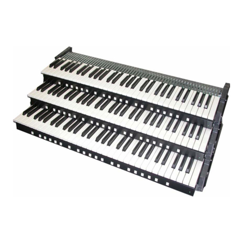
Classic Organ Works CMK-1 User manual

Dmbttjd!Pshbo!Xpslt!
CMK-1
Classic MIDI Keyboard
User Manual
Version 1.00.05
Div. of:
ARTISAN CLASSIC ORGAN INC.


_________________________________________________________________________________________________________
CMK-1 Manual (Issue-1) Page-3 October 20, 2004
CLASSIC MIDI KEYBOARD
CMK-1
TABLE OF CONTENTS
LIMITED WARRANTY ............................................................................................... 9
INTRODUCTION ...................................................................................................... 11
Description....................................................................................................................................11
Table 1: Parts/Components List ............................................................................................................................... 12
Figure 1: CMK components ..................................................................................................................................... 12
Figure 2: CMK connections ..................................................................................................................................... 13
INSTALLATION ....................................................................................................... 15
Springs ..........................................................................................................................................15
Figure 3: Steps in replacing a dislocated spring...................................................................................................... 15
Mounting .......................................................................................................................................15
Figure 4: Single-manual stand-alone....................................................................................................................... 16
Figure 5: Single-manual with wooden case............................................................................................................. 16
Figure 6: Two manual setup .................................................................................................................................... 16
Figure 7: Three manual setup.................................................................................................................................. 17
Figure 8: Two/Three-manual setup mounted level .................................................................................................. 17
Figure 9: Two/Three-manual setup mounted ‘tilt-up’ ............................................................................................... 18
Figure 10: Accessing keyboard electronics ............................................................................................................. 18
Connections..................................................................................................................................18
Power....................................................................................................................................................................... 18
Figure 11: Connecting Multiple CMK Keyboards, Rear View, Using Parallel Wiring and Included Power Supply . 19
MIDI ......................................................................................................................................................................... 19
Figure 12: MIDI Connection Jacks, Rear View........................................................................................................ 19
Analog Inputs ........................................................................................................................................................... 20
Figure 13: Wiring Schematic for Analog input ......................................................................................................... 20
Table 2: Connection Chart........................................................................................................................................ 20
Software Installation (Windows users only)............................................................................................................. 21
MIDI SPECIFICATION ............................................................................................. 22
MIDI Sound Sets ...........................................................................................................................22
General MIDI............................................................................................................................................................ 22
Table 3: Sound Set Groups ...................................................................................................................................... 23
Table 4: General MIDI Program Numbers for MIDI Channels 1-9 and 11-16 .......................................................... 24
Table 5: General MIDI Percussion Key Map for MIDI Channel 10........................................................................... 25
Ahlborn..................................................................................................................................................................... 25
Table 6: Classic Module ........................................................................................................................................... 25

_________________________________________________________________________________________________________
CMK-1 Manual (Issue-1) Page-4 October 20, 2004
Table 7: Romantic Module........................................................................................................................................ 26
Table 8: 201 Module ................................................................................................................................................. 26
Table 9: 202 Module ................................................................................................................................................. 26
HAUPTWERKTM....................................................................................................................................................... 27
Table 10: MIDI messages relevant to Hauptwerk .................................................................................................... 27
SCPOPTM ................................................................................................................................................................. 27
MIDI Hardware Specification .......................................................................................................28
Figure 14: Schematic of 5-pin DIN connector.......................................................................................................... 28
CMK HARDWARE CONFIGURATION.................................................................... 29
Introduction...................................................................................................................................29
Power-On Self Test.......................................................................................................................29
Analog Input Pins .........................................................................................................................29
MIDI Crescendo ....................................................................................................................................................... 29
MIDI Volume ............................................................................................................................................................ 29
MIDI Expression....................................................................................................................................................... 29
Programming ................................................................................................................................30
Table 11: Piston programming functions .................................................................................................................. 30
CMK SOFTWARE CONFIGURATION..................................................................... 32
Introduction...................................................................................................................................32
Software Installation.....................................................................................................................32
Figure 15: Upon clicking on the ‘CMK_Setup.exe’ file, the above window will appear. .......................................... 33
Figure 16: Allows the user to select a directory to install the CMK program file ..................................................... 33
Figure 17: Setup adds an icon to the start menu for convenient access................................................................. 34
Figure 18: Setup provides the option of creating an icon on the Windows desktop................................................ 34
Figure 19: Confirmation window .............................................................................................................................. 35
Figure 20: Setup progress window .......................................................................................................................... 35
Figure 21: Confirms installation was successful...................................................................................................... 36
Software Startup ...........................................................................................................................37
Figure 22: CMKConfig software startup screen....................................................................................................... 37
Figure 23: CMKConfig software main menu............................................................................................................ 37
Configure a CMK from scratch....................................................................................................38
Figure 24: CMKConfig software attempting to connect with the CMK .................................................................... 38
Figure 25: CMKConfig software unable to connect................................................................................................. 38
Figure 26: CMKConfig software successfully connected to the CMK. .................................................................... 38
Figure 27: Successful connection between CMKConfig software and CMK...........................................................39
Figure 28: Window confirms the loading of pre-configuration data from the CMK to the PC.................................. 39
Load a previously saved CMK configuration .............................................................................40
Figure 29: Configuration File selection window. ...................................................................................................... 40
Figure 30: Program window..................................................................................................................................... 40

_________________________________________________________________________________________________________
CMK-1 Manual (Issue-1) Page-5 October 20, 2004
Functions of the Toolbars............................................................................................................41
Figure 31: Toolbars in CMKConfig software............................................................................................................ 41
1. File Menu ............................................................................................................................................................ 41
Figure 32: Loading Program Data From File Window ............................................................................................. 41
Figure 33: Save Program Data to File Window ....................................................................................................... 42
Figure 34: Confirm replacing of file window............................................................................................................. 42
Figure 35: Software attempting to make a connection with the CMK...................................................................... 43
Figure 36: Software unable to make a connection with the CMK............................................................................ 43
Figure 37: Software detecting number of keyboards............................................................................................... 43
Figure 38: Successful connection between CMK and PC software ........................................................................ 44
Figure 39: Confirms loading of configuration into CMKConfig software.................................................................. 44
Figure 40: Software attempting to communicate with CMK ................................................................................... 44
Figure 41: Successful Software connection to the CMK ......................................................................................... 45
Figure 42: Confirms configuration written to CMK from CMKConfig software. .......................................................45
2. Options Menu...................................................................................................................................................... 45
Figure 43: MIDI Input Output Setup window............................................................................................................ 45
2. Help Menu...................................................................................................................................................... 46
Figure 44: Help Menu .............................................................................................................................................. 46
Keyboard Functions .....................................................................................................................46
Figure 45: Clicking on the keys of the keyboard invokes a MIDI Channel select menu.......................................... 47
Figure 46: Clicking on an individual piston invokes the Piston function select drop-down menu. .......................... 47
Table 12: Customizable Functions for each piston .................................................................................................. 48
Configuring Multiple Keyboards .................................................................................................49
REFERENCES ......................................................................................................... 51
APPENDIX A: .......................................................................................................... 53
DIP SWITCH CONFIGURATION TABLE ................................................................ 53
Table 13: DIP Switch settings and their corresponding Configuration numbers ...................................................... 53
APPENDIX B: .......................................................................................................... 56
MIDI PROTOCOL SPECIFICATION ........................................................................ 56
MIDI Protocol Specification .........................................................................................................56
Channel Messages .................................................................................................................................................. 56
System Messages.................................................................................................................................................... 57
Running Status ........................................................................................................................................................ 57
Table 14: MIDI 1.0 Specification Message Summary .............................................................................................. 58
Table 15: Expanded Status Bytes List...................................................................................................................... 61
Table 16: Control Changes and Mode Changes ...................................................................................................... 64
Table 17: Registered Parameter Numbers............................................................................................................... 67
APPENDIX C: .......................................................................................................... 69
SYSTEM EXCLUSIVE MESSAGE LAYOUTS ........................................................ 69

_________________________________________________________________________________________________________
CMK-1 Manual (Issue-1) Page-6 October 20, 2004
Messages common to all products .............................................................................................69
General Information Identity Request...................................................................................................................... 69
General Information Identity Reply .......................................................................................................................... 69
CMK -- Special layouts .................................................................................................................69
APPENDIX D: .......................................................................................................... 71
AHLBORN MESSAGES .......................................................................................... 71
Table 18: Note On/Off MIDI functions to control Ahlborn Archive sound modules .................................................. 71
Table 19: Ahlborn Archive ‘ROMANTIC’ sound module commands for stops and couplers ................................... 72
Table 20: Ahlborn Archive ‘CLASSIC’ sound module commands for stops and couplers on .................................. 73
Table 21: Ahlborn Archive ‘202’ sound module commands for stops and couplers................................................. 74
Table 22: Ahlborn Archive ‘201’ sound module commands for stops and couplers................................................. 75
Table 23: Ahlborn Archive sound module Piston and Crescendo input functions for all four units.......................... 76
Table 24: Ahlborn Archive sound module additional Piston input commands .........................................................77
Table 25: Ahlborn Archive and other MIDI sound modules analog input function commands................................. 77
APPENDIX E:........................................................................................................... 79
SCPOP MESSAGES................................................................................................ 79
Table 26: General MIDI Pipe Organ Emulation Upper Manual for SCPOP ............................................................. 79
Table 27: General MIDI Pipe Organ Emulation Lower Manual SCPOP ..................................................................81
Table 28: General MIDI Pipe Organ Emulation Pedals SCPOP .............................................................................. 84
APPENDIX F:........................................................................................................... 85
CIRCUIT BOARD SCHEMATICS ............................................................................ 85
Figure 47: CMK1-1 Classic MIDI Keyboard Circuit board 1 Silk Screen................................................................. 85
Figure 48: CMK1-1 Classic MIDI Keyboard Circuit board 1 schematic................................................................... 86
Figure 49: CMK1-2 Classic MIDI Keyboard Circuit board 2 Silk Screen................................................................. 87
Figure 50: CMK1-2 Classic MIDI Keyboard Circuit board 2 schematic................................................................... 88
Figure 51: CMKPR1-1 Classic MIDI Keyboard Piston Rail board 1 Silk Screen..................................................... 89
Figure 52: CMKPR1-1 Classic MIDI Keyboard Piston Rail board 1 schematic....................................................... 90
Figure 53: CMKPR1-2 Classic MIDI Keyboard Piston Rail board 2 Silk Screen..................................................... 91
Figure 54: CMKPR1-2 Classic MIDI Keyboard Piston Rail board 2 schematic....................................................... 92
APPENDIX G: .......................................................................................................... 93
MECHANICAL DRAWINGS..................................................................................... 93
Figure 55: Two-manual CMK mounted level ........................................................................................................... 93
Figure 56: Two-manual CMK mounted tilted-up...................................................................................................... 94
Figure 57: Three-manual CMK mounted level......................................................................................................... 95
Figure 58: Three-manual CMK mounted ‘tilt-up’...................................................................................................... 96
Figure 59: CMK Piston Rail front panel mechanical drawing .................................................................................. 97
Figure 60: CMK Piston Rail Mounting rail mechanical drawing............................................................................... 98
Figure 61: CMK Piston Rail circuit board mounting rail mechanical drawing.......................................................... 99
Figure 62: CMK Side mounting bracket mechanical drawing (treble end) ............................................................ 100
Figure 63: CMK Side mounting bracket mechanical drawing (bass end).............................................................. 101

_________________________________________________________________________________________________________
CMK-1 Manual (Issue-1) Page-7 October 20, 2004
Figure 64: CMK End clamp mechanical drawing................................................................................................... 102
Figure 65: CMK two-manual mounting bracket mechanical drawing .................................................................... 103
Figure 66: CMK three-manual mounting bracket mechanical drawing.................................................................. 104
DISCLAIMER ......................................................................................................... 105


_________________________________________________________________________________________________________
CMK-1 Manual (Issue-1) Page-9 October 20, 2004
CLASSIC MIDI KEYBOARD
CMK-1
LIMITED WARRANTY
Classic Organ Works warrants the Classic MIDI Keyboard (CMK) to be free from defects in materials and
workmanship under normal use for a period of ONE YEAR from the delivery date. This warranty applies
only if the product is owned by the original purchaser who has the bill of sale.
This warranty explicitly excludes any cables provided with the CMK, which may become defective as a
result of normal wear and tear. The DC power adaptor is included in the warranty however.
In the event of a defect in materials or workmanship, please contact Classic Organ Works immediately. In
particular, defects due to shipping should be reported within 15 days for insurance claim purposes. For all
other defects, Classic Organ Works agrees to repair or replace all defective parts of said products which are
returned, transportation prepaid, for inspection at its service centre within the period of the warranty.
In the event that Classic Organ Works determines the product requires repair because of user misuse or
regular wear, it will assess a fair repair or replacement fee. The customer will have the option to pay this fee
and have the unit repaired and returned, or not pay this fee and have the unit returned un-repaired.
Classic Organ Works will not be liable for consequential, special, indirect, or similar damages or claims
including loss of profit or any other commercial damage, and in no event will Classic Organ Works’ liability
for any damages to the purchaser or any other person exceed the price paid for the product, regardless of any
form of the claim. Classic Organ Works specifically disclaims all other warranties, expressed or implied.
Specifically, Classic Organ Works makes no warranty that the product is fit for any particular purpose.
This warranty shall be interpreted, and governed by applicable laws in the province of Ontario, Canada. If
any provision of this warranty is found void, invalid or unenforceable, it will not affect the validity of the
balance of the warranty, which shall remain valid and enforceable according to its terms. In the event any
remedy hereunder is determined to have failed of its essential purpose, all limitations of liability and
exclusion of damages set forth herein shall remain in full force and effect.


_________________________________________________________________________________________________________
CMK-1 Manual (Issue-1) Page-11 October 20, 2004
CLASSIC MIDI KEYBOARD
CMK-1
INTRODUCTION
Description
Congratulations! You are now the proud owner of the CMK (Classic MIDI Keyboard). The CMK combines
technology and classical church organ ideas into an innovative MIDI device. With the CMK, MIDI sound modules
may be controlled as if they were part of the organ. Designed as a portable unit, it features a ‘stackable’ feature so that
users may customize a complete practice organ to their specification. With a quality construction, various structural
and electronic design elements, and user-friendly configuration software, the CMK will provide many years of worry-
free musical enjoyment for all users.
The CMK is designed for organists, organ enthusiasts, and MIDI users. Key-switch information from the keyboard
and pistons is converted into MIDI control data by the on-board micro-controller. For instance, a MIDI message
defines whether a key was pressed or released, the MIDI channel that the information should be transmitted on and the
key number pressed or released. As many as three CMK keyboards may be daisy-chained.
Each CMK keyboard also has 20 pistons to control features such as coupling and effects. The CMK can
simultaneously drive up to four Ahlborn Archive Series™ modules that generate pipe-organ voices. In addition, any
MIDI-controlled sound module or PC-based synthesizer software may be connected. These pistons are also used for
programming the CMK. Combinations of pistons and keyswitches are used for functions such as a reboot, setting the
MIDI output channel, turning on and off velocity sensing, and setting the volume output.
There are two analog inputs which can be configured as volume/expression and crescendo inputs. By adjusting the
analog device, a unique voltage reading is produced on the analog input pin which is interpreted by the
microprocessor. In the case of a volume adjustment, a MIDI message will send to the MIDI-controlled device the
loudness level of the stop or sound. MIDI messages are also sent for a crescendo adjustment which will gradually add
stops to a registration.
The CMK is completely customizable using the included ‘CMKConfig’ software. Up to 128 configurations may be
programmed into the CMK. As many as three keyboards each with twenty pistons and two analog inputs may be
configured for Ahlborn Archive modules, General MIDI sound modules, and MIDI-controlled PC-based synthesizer
software. The software is capable of customizing the CMK for use with organ computer simulation software such as
Hauptwerk and the Sound Canvas Pipe Organ Project (SCPOP).
Configurations are saved as computer files which may be stored in the user’s home computer, or in the CMK.
Configurations that are saved on the CMK will not be lost when power is turned off because the memory is non-
volatile. These configurations may be selected using DIP-switches on the CMK. Eventually, users may inexpensively
upgrade their software as well as configurations by visiting the Classic Organ Works website at
http://www.organworks.com.

_________________________________________________________________________________________________________
CMK-1 Manual (Issue-1) Page-12 October 20, 2004
The following is a list of parts for each CMK setup.
Table 1: Parts/Components List
A B C
D E F
Figure 1: CMK components (from L-R, Top to Bottom):
A) Keyboard
B) 2-manual side mounting brackets (sold separately)
C) 3-manual side mounting brackets (sold separately)
D) 12V DC wall adaptor
E) 6-Ft. MIDI cable
F) Mounting screw.
Setup Items
A B C D E F
Manual(s) 2-Manual
Side Bracket
set (sold
separately)
3-Manual
Side Bracket
set (sold
separately)
12V DC
adaptor
MIDI
Cable(s)
Mounting
Screws
One Manual 1 - 1 1
One Manual and
Wood Case
1 - 1 1
Two Manuals 2 2 1 2 4
Three Manuals 3 - 2 1 3 6

_________________________________________________________________________________________________________
CMK-1 Manual (Issue-1) Page-13 October 20, 2004
Figure 2: CMK connections


_________________________________________________________________________________________________________
CMK-1 Manual (Issue-1) Page-15 October 20, 2004
CLASSIC MIDI KEYBOARD
CMK-1
INSTALLATION
IMPORTANT
READ THIS DOCUMENT BEFORE INSTALLATION
Upon receiving this unit, remove any packing material inside the unit that may have been included to
prevent movement of components or wiring during shipping.
(For internal access, ensure the unit is disconnected from all power sources.)
Springs
The keyboard contact springs are installed at Classic Organ Works. However, the nature of these contacts makes them
sensitive to movements during shipping. A visual inspection of the keyboard should be performed upon receiving to
determine if any of these springs have become displaced. A package of five spare springs is included with every
keyboard. To replace the missing springs you will need tweezers and gloves/paper towel. Then follow these
directions:
NOTE: DO NOT HANDLE THE SPRINGS WITH YOUR BARE FINGERS. THE SPRINGS ARE COATED WITH
A LAYER OF SILVER WHICH CAN DETERIORATE IF HANDLED.
1. Pick up the spring using tweezers to gently grip the middle of the spring.
2. Feed one end of the spring in between the two bus bars. Then slide the other end of the spring into the
upper hole (with the keyboard circuit board facing up) of the keyboard keys plastic actuator.
3. With one end of the spring firmly positioned, use the tweezers to grasp the other end of the spring roughly
0.5cm from the end of the spring.
4. SLOWLY stretch this end and position it into the metal spring holder on the circuit board. THE
SPRINGS DEFORM EASILY. USE EXTREME CAUTION TO AVOID OVER-STRETCHING
THE SPRINGS.
1 2 3 4
Figure 3: Steps in replacing a dislocated spring
Mounting
Mounting of the CMK is specific to each customized setup. It can be mounted into a wooden case, into an existing
console, or using metal brackets. In the single keyboard configuration, the CMK is a stand-alone unit. In this
configuration, the keyboard is mounted using metal brackets. However, for a professional finish, an optional wooden

_________________________________________________________________________________________________________
CMK-1 Manual (Issue-1) Page-16 October 20, 2004
mounting box may be purchased. When mounted in the wooden mounting box, the electronics may be accessed by
removing four screws on the bottom of the wooden case. The CMK keyboard then slides out easily. In both the single
manual and wooden mounting box versions, the CMK is a ready-to-play keyboard requiring only power and MIDI
connections.
Figure 4: Single-manual stand-alone
Figure 5: Single-manual with wooden case
If the CMK is to be mounted into an existing console, the metal pieces at the ends of the keyboard have holes of 0.156
inch diameter to allow the CMK to be fastened to wooden end cheeks using #6 screws.
In the two-keyboard and three keyboard configurations, a separate mounting bracket may be purchased. There are
three threaded holes on the sides of the keyboards for mounting purposes. The holes permit mounting of the keyboards
into the brackets either level or tilted as shown in Figures 8 and 9. The entire two/three keyboard configuration with
mounting brackets may be installed in a console using #6 screws. The electronics are accessible by flipping the
keyboards as shown in Figure 10.
Figure 6: Two manual setup

_________________________________________________________________________________________________________
CMK-1 Manual (Issue-1) Page-17 October 20, 2004
Figure 7: Three manual setup
Figure 8: Two/Three-manual setup mounted level
(Note the pivoting screw positions on each end bracket are different)

_________________________________________________________________________________________________________
CMK-1 Manual (Issue-1) Page-18 October 20, 2004
Figure 9: Two/Three-manual setup mounted ‘tilt-up’
Figure 10: Accessing keyboard electronics
Connections
Power
The user must connect Power and MIDI for each keyboard. There are several ways to provide power to the CMK
which will depend on the application. The CMK requires between +9V and +15V DC power at a minimum current of
400mA. If the CMK is to be used as a standalone unit, the most convenient method of providing power would be to
use the supplied 2.1mm Co-axial DC adaptor.

_________________________________________________________________________________________________________
CMK-1 Manual (Issue-1) Page-19 October 20, 2004
Figure 11: Connecting Multiple CMK Keyboards, Rear View, Using Parallel Wiring and Included Power Supply
However, if multiple keyboards are used or if the CMK is to be mounted inside an organ console, the 4-input terminal
block can be connected to an existing organ power supply. Power and ground are connected to terminal block inputs 1
and 2 respectively. Terminal block inputs 3 and 4 are for grounding the case. One power supply can power up to three
CMK keyboards by paralleling the terminal block connections.
The CMK has a number of safety features. For easy operation, an isolated +12 Volt, DC adaptor of either positive or
negative polarity may be used. It must have a 2.1mm co-axial power jack. A bridge-rectifier is present within the
CMK to ensure the proper polarity. A 500mA self-resetting Polyfuse provides over-current protection from the
common power supply.
MIDI
The CMK has one MIDI input and four paralleled MIDI outputs so that it can be connected to several MIDI devices
and/or a personal computer. All four MIDI OUT connectors produce the same messages and can be used for long
distance applications. The MIDI IN connector allows another MIDI source to be merged with the MIDI signal from
this unit.
Figure 12: MIDI Connection Jacks, Rear View
The CMK has the capability to simultaneously drive up to four different Ahlborn Archive SeriesTM modules. These
can be controlled through the general pistons on the CMK. Thus, additional stops and sounds on multiple Ahlborn
Archive modules may be controlled as though they were part of the organ.

_________________________________________________________________________________________________________
CMK-1 Manual (Issue-1) Page-20 October 20, 2004
Analog Inputs
Two analog inputs are present on the CMK. The user must ensure that there is one connection to Ground on pin ‘3’,
one connection to an appropriate positive voltage (usually +5V) on pin ‘1’, and one connection to an analog input pin.
Analog inputs are used for crescendo and volume/expression adjustment as shown in Figure 13.
Figure 13: Wiring Schematic for Analog input
The CMK has provision for up to four extra input functions on the circuit board. These inputs are reserved for future
use.
Table 2: Connection Chart
Connection Name Connection Type Hardware Description
Required Connections
Power Input 1. Co-ax 2.1mm (either polarity)
OR
2. 4-input Terminal Block
Input 1 for +12V, Input 2 for GND
9-12V, 400mA minimum
MIDI IN Input DIN 5-pin socket 180° Standard MIDI signals
MIDI OUT 1-4 Output DIN 5-pin socket 180° Standard MIDI signals
Optional Connections
Analog Input Pins, 0.025”Square,
0.3”long, 0.1”pitch
‘Analog Input 1’ is used for
crescendo and ‘Analog Input 2’ is
used for volume/expression.
Table of contents
Other Classic Organ Works Electronic Keyboard manuals
