Classic tracker OBD-II User manual

Classic Tracker Installation Guide
v1.5 [FMA120/FMA204] 180123
1
Classic Tracker Installation
Thank you for purchasing a Classic Tracker!
We believe you’ve bought the most dedicated, effective and secure classic car & bike alerting,
monitoring and live-vehicle tracking service. We hope it brings you many years of efficient service!
We recommend you read this entire document prior to getting started. Should you require ANY
assistance, we’re happy to help so please feel free to contact us. As classic car and bike
enthusiasts, we’re never tired of classic conversation.
Four Simple Steps...
There are four simple steps to install, connect & power, register and confirm your tracker is
successfully installed.
1.
FIND YOUR
TRACKER
SERIAL NUMBER
2.
INSTALLATION &
WIRING TO YOUR
CAR/BIKE
3.
REGISTER
THE
TRACKER
4.
ACCESS
ON-LINE
TRACKING
Classic Tracker Ltd.
t: +44 (0)20 8265 0425
w: www.classic-tracker.com
e: info@classic-tracker.com
C
L
A
S
S
I
C
T
R
A
C
K
E
R

Classic Tracker Installation Guide
v1.5 [FMA120/FMA204] 180123
2
FIND YOUR TRACKER SERIAL NUMBER
Please make a note of the serial number, which is found on a label on top of the tracker. You will
need this later when registering your tracker on our website.
Tracker Serial Number:
INSTALLATION & WIRING TO YOUR CAR/BIKE
TRACKER-UNIT INSTALLATION:
Please consider ‘test-mounting’ the powered tracker prior to final fitment where you can see the
two LEDs (light-emitting diodes) on the device. Ensure the vehicle is outside with an unobstructed
view of the sky and that the vehicle ignition is on. Both GPS and GSM can take about 90 seconds to
acquire a signal.
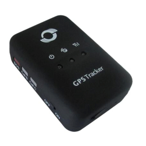
There are three types of tracker available: OBD-II, WIRED-Standard and WIRED-IP67 (waterproof).
The first plugs in to the OBD-II port in your car (if you have an OBD-II port) and the other variants
use a wiring assembly.
The Classic Tracker has internal GPS and GSM antennae. The device should be mounted with the
sticker facing open sky.
OBD-II Tracker
The OBD-II type tracker requires no additional wiring unless there isn’t enough room to plug the
tracker in to the port in your car. If that’s the case an extension cable can be supplied. Please
contact us for details.
Wiring Assembly Tracker:
This type of Classic Tracker is supplied either as a two-part assembly (tracker & wiring loom) or
(single combined tracker/loom). The assembly is designed to be able to fit into your vehicle without
making significant changes to the vehicle-wiring loom. The WIRED-Standard has a plug that plugs
into the tracker unit itself. It is designed this way in case you wish to remove the tracker without
disturbing the supplied wiring loom following installation. The tracker unit should be installed
securely, ideally in a covert location with the ‘a view to the sky’.
1.
2.

Classic Tracker Installation Guide
v1.5 [FMA120/FMA204] 180123
3
COVERT LOCATION
•For cars, we recommend two places; either within a bulkhead cavity hidden in the front
dashboard, or alternatively in the rear of the vehicle hidden immediately beneath the rear-
parcel shelf. In either case locate the tracker covertly, ensuring that the upper-side of the
unit sits just beneath the underside of the dash-top/ parcel shelf.
•For motorcycles, within any cowling or covers protecting the frame of the bike. Although the
motorcycle version of the Classic Tracker is IP67 rated (waterproof) we advise against
installing anywhere near where water collects (e.g. mudguard enclosures). Worth noting
that many saddles are manufactured with an internal metal frame/mesh. Therefore
mounting immediately beneath the saddle is not necessarily recommended.
You can, of course, locate the tracker wherever you wish to make it difficult for the would-be-thief
to find. Ideally the tracker should have little, or no, metal immediately above it to prevent its ability
to receive GPS signals. Note that the tracker will still operate within the steel/metal fabrication of
your car.
When finding the ideal place for your vehicle, consider how you will route the cable assembly to
Permanent LIVE, NEUTRAL and SWITCHED IGNITION and Remote IMMOBILSER.
CABLE WIRING
IMPORTANT! Disconnect the main battery from your vehicle whilst connecting the tracker’s
wiring loom to your vehicles power supply.
The wiring loom supplied with the Classic Tracker contains multiple cables. The tracker only
requires three connections to provide full service. A fourth cable should be used when connecting
the optional Remote IMMOBILISER.
IMPORTANT: The earlier 2017 WIRED IP67 (Waterproof) versions of the Wired tracker have
different colour schemes. For clarification, if you purchased your WIRED-IP67 Classic
Tracker in 2017, then follow the 2017 instructions below.
If in any doubt, please contact us prior to connection:
WIRED-Standard
2018> WIRED-
IP67
(Waterproof)
2017 WIRED-
IP67
(Waterproof)
Connection Scheme
RED
RED
RED
This should be connected to +12V /permanent
live
BLACK
BLACK
BLUE
This should be connected to 0V/Ground
YELLOW
YELLOW
YELLOW
This should be connected to +12V Switched
Ignition (e.g. if your cigarette-lighter or radio only
powers up once the engine is started, this is
Switched Ignition)
WHITE with
Orange tracer
WHITE with
Orange tracer
WHITE
Connects to optional Immobiliser relay. Please
refer to separate Classic-Tracker-External-Relay-
Connection-Guide.

Classic Tracker Installation Guide
v1.5 [FMA120/FMA204] 180123
4
POSITIVE EARTH: For connection to a vehicle with a positive-earth arrangement, please ensure that
the above wiring scheme is reversed (i.e. red to positive-earth and black/blue to supply).
All remaining cables are for the connection of additional functions to the tracker and are presently
disabled on all our tracking services (unless you are using the optional Immobiliser Pack).
Once the wiring assembly has been installed, next plug the tracker unit in to the loom (if
appropriate for your model of tracker).
You may now reconnect your vehicles’ battery. Having now applied power to the Classic Tracker,
you should see a pair of LEDs (light-emitting-diodes) gently flashing as the tracker locates both a
GPS location and cellular connection.
LED Status Indicators
Having powered the tracker, please ensure that both LEDs flash at intervals of approximately one
second. The Status light may also flash in bursts as the device communicates with our systems (see
table below).
The Navigate LED indicates the status of the GPS receiver in the Tracker. The STATUS light
indicates the GSM (Mobile Signal) status. If the Navigate LED is permanently on OR off then the
Tracker is failing to receive a GPS signal and won’t be able to track the movement of the vehicle
and you should consider positioning it somewhere else.
NAVIGATE LED
Behaviour
Explanation
Possible Cause/Action
Permanently Illuminated
Not receiving GPS signal
Ensure tracker is facing open sky,
label face-upwards and not
covered by metal obstructions
Blinking every second
Normal mode, GPS signal is received
and working
Permanently Off
GPS is turned off; potentially in sleep
mode
Lightly move tracker or vehicle to
wake tracker.
Permanently Off
Insufficient power to tracker
Ensure tracker is correctly wired
and has >9V DC supply.
STATUS LED
Behaviour
Explanation
Possible Cause/Action
Blinking every second
Normal Operation, GSM signal is
received and working
Blinking every two seconds
Tracker is in sleep mode
Rapid blinking in bursts
Normal Operation. GSM is
communicating.
Rapid & continual blinking
Normal Operation. Tracker is booting.
Permanently Off
Tracker not working;
Insufficient power to tracker;
Firmware being updated.
Ensure tracker is correctly wired
and has >9V DC supply.

Classic Tracker Installation Guide
v1.5 [FMA120/FMA204] 180123
5
Further detail on wiring your tracker and installation is provided at the end of this document.
Please note that your tracker is fitted with a special multi-operator SIM card and will connect to the
strongest mobile phone signal in your location. Please make no attempt to remove the SIM card
from the tracker unit as this will invalidate your warranty.
Again, please ensure you have made a note of the Tracker Serial Number before moving to the
next step.
REGISTER THE TRACKER
Please visit the support area of our website to register the tracker with your vehicle:
www.classic-tracker.com
Activation can take up to one business day. You will receive notification that the tracker has been
successfully registered on our secure systems. Login credentials for web portal and mobile app will
be provided.
ACCESS ON-LINE TRACKING
PLEASE NOTE: This service is ONLY available to those customers who have subscribed to either
the SAFER, or SAFEST services.
After registration is complete, you will have received an email providing login and password for the
Classic Tracker Portal and mobile app. The LOGIN link is available from our website.
Full instructions and help are provided once logged in the portal.
You may also download an Android or iOS App called X-Monitor. Use the same login credentials to
access when using the App. Please visit Google Play or App Store on your mobile device to
download.
3.
4.

Classic Tracker Installation Guide
v1.5 [FMA120/FMA204] 180123
6
Further WIRING Recommendations
Wires should be connected while module is not plugged in/ or the vehicle battery is disconnected.
Wires should be fastened to the other wires or non-moving parts. Try to avoid heat emitting and
moving objects near the wires. If factory isolation was removed while connecting wires in to the
loom, it should be re-applied when the fitting is finished and tested. If the wires are placed outside
or in places where they can be damaged or exposed to heat, humidity, dirt, etc., additional
isolation should be applied to the connections. Wires cannot be connected to the board of vehicle
computers or control units.
Connecting Power Source
Be sure that the power to the tracker is a CONSTANT SOURCE Supply. i.e. ensure that when the
vehicle is turned off, power stays permanently on the RED wire.
When module is connected, voltage should not drop below 9v. It is recommended to connect to
the main power cable in the fuse box where possible.
Connecting Ignition Wire
Be sure to check that this connection is to a real ignition wire. i.e. power does not disappear while
the engine is running.
Check this is not an ACC wire (when key is in the first position, most electronics of the vehicle are
available).
Check if power is still available when you turn off any of vehicles devices.
Connecting Ground Wire
Ground wire should be connected to the vehicle frame or metal parts that are fixed to the frame. If
the wire is fixed using a bolt, the loop must be connected to the end of the wire. In some cases
consider removing paint to expose the metal of the vehicle where loop is connected.
NOTE: Connecting the power supply must be carried out using a very low impedance point on-
board the vehicle. The best points in the vehicle are the battery terminals. Therefore, we
recommend connecting the power of tracker directly to the battery terminals. If this is not possible,
another option is to connect the tracker to the main fuse box.
Connection of the GROUND cable must be made to a true vehicle-GND connection point. i.e. a
zero-volt, low impedance path back to battery-GND. Connecting the GND at an arbitrary point to
the mass of the car is unacceptable, as static and fluctuating voltages on the GROUND line can
cause unpredictable tracker behaviour, or even lead to an unstable tracker installation; potentially
even its failure.
This manual suits for next models
2
Table of contents
