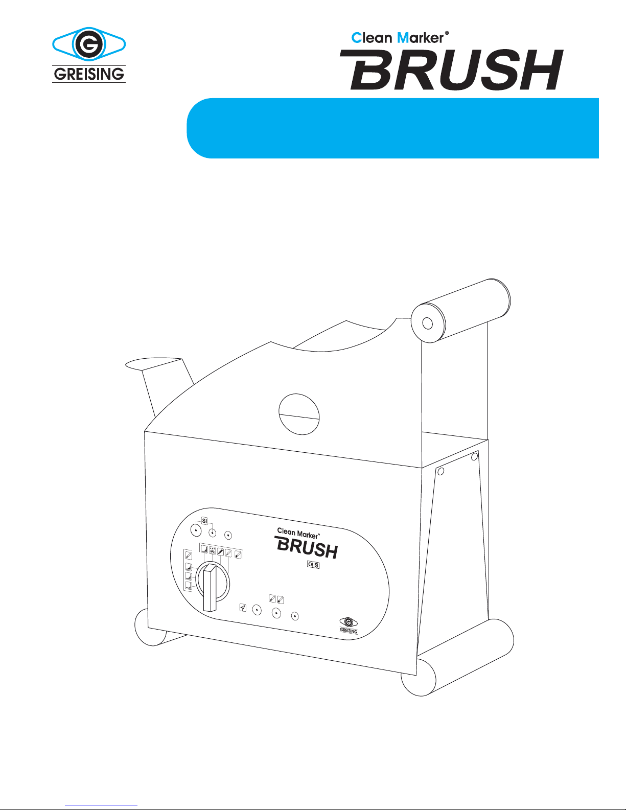
Clean Marker Brush-E User manual
www.greising.com
Made in Germany
1
2
3
4 5 6 7
Operation Manual
Brush-E ∙ Brush- S ∙ Brush-P ∙ Brush-T ∙ Brush-TP

Kai GreisinG e. K.
Clean MarKer
www.greising.com
Info@greising.com
Industriestraße 29/2
D-73340 Amstetten
Tel.+49 (0)73 31/30 58 - 0
Fax +49 (0)73 31/98 17 22
ORDER PROCESSING
+ 49(0)73 31/30 58 - 20
ORDERING STENCILS
+ 49(0)73 31/30 58 - 22
Operation Manual Clean Marker Brush −Page 2
instructions for use
PRODUCT DESCRIPTION
Model:
Unit No.:
Built:
CUSTOMER REGISTRATION
Stock No.:
THE USER IS OBLIGED TO:
• observationofECRegulations89/655andtheir
national implementation
• observationofthecurrentnationalregulations
concerning industrial safety
• utilisationofthemachineinaccordancewithin-
structions
Allrightsreserved.
Printing, in whole or in part, is only allowed
with prior consent of the manufacturer.
Errorsandomissionsexcepted.

Operation Manual Clean Marker Brush −Page 3
index
1 saFeTY reGUlaTiOns 5
1.1 Correct utilisation 5
1.2 Tips and definitions 5
1.3Obligationsandliability 5
2 inTrOdUCTiOn 7
2.1 Technical data 7
2.2 Conformity 7
2.3Generalview 8
2.4 Accessories 8
3 FUnCTiOn, MeTHOd OF OPeraTiOn 8
3.1Functionreview 8
3.2 Method of operation 9
3.3 Safety and monitoring equipment 9
3.4Switchingoversupplyvoltage 9
3.5 Operating and display elements 9
4 TransPOrT, seTTinG UP 12
4.1 Safety regulations 12
5 OPeraTinG 12
5.1 Initial operation 12
5.2 Cleaning with the Clean Marker Brush attachment 13
5.3 Marking with the Clean Marker Brush (flat tool head) 14
5.4 Dealing with short-term stencils 15
5.5 Closing down the unit 15
5.6BlastingwiththeCleanMarkerBrush-TandBrush-TP 15
5.7 Connecting up the automatic electrolyte feed on
CleanMarkerBrush-PandBrush-TP 16
6 MainTenanCe 17
6.1Safetyregulations 17
6.2Generalremarks 17

instructions for use
7 FaUlTs 18
7.1 Correcting faults 18
8 serViCinG 21
8.1 Safety regulations 21
9 ClOsinG dOWn, sTOrinG 21
9.1 Preparing for storage 21
9.2 Packaging, transporting and retransporting 21
9.3 Maintenance during storage 21
10 disPOsal 21
10.1 Method of procedure 22
11 YOUr OPiniOn 23
12 deClaraTiOn OF COnFOrMiTY 24
Operation Manual Clean Marker Brush −Page 4

1 saFeTY reGUlaTiOns
1.1 CORRECT UTILIZATION
Theunitsareintendedforcleaningweldedseams,forremovingoxide
coatingonstainlesssteelweldedseams,foretchingconductivemetal
surfacesandforgalvanizingandblastingsmallareas.Thefunctionisonly
guaranteedwhenoriginalpartsareused.Anyotheroranyusebeyond
thosedeterminedisnotconsideredtobecorrect.
Themanufacturecannotbeheldresponsibleforanydamagesresulting
from such incorrect use.
Thefollowingarealsoconsideredtobepartofcorrectutilization:
•Compliancewithinstructionsonuse.
•Compliancewithinspectionandmaintenancerequirements.
•Useofprotectiveclothing,especiallyglovesandgoggles.
1.2 TIPS AND DEFINITIONS
Warning
A possibly dangerous situation which could lead to serious
injury or even death.
Warning
A possibly dangerous situation, which could lead to light
physical injury. This sign is also used as a warning for heavy
material damage.
Information
Concerning usage and other useful information.
Information
The arrow describes a following process occurring automati-
cally and / or the condition which should now be set.
1.3 OBLIGATIONS AND LIABILITY
1.3.1 Necessary qualications of operators
Operation,maintenanceandinspectionmayonlybecarriedoutbyautho-
risedandqualiedspecialists.Theminimumageoftheoperatoris18.
Authorisedspecialistsareunderstoodtobespecialiststrainedbytheuser,
themanufacturerortheservicepartner.
Theseoperatorsmustbe:
• trainedintheuseoftheunit
• conversantwiththeinstructionsforuse
• conversantwiththesafetyequipmentoftheunit
• conversantwiththerelevantregulations,(especiallywithaccident
preventionregulations)
• authorisedtousethenecessarychemicals
Operation Manual Clean Marker Brush −Page 5

instructions for use
1.3.2 Risks involved when using the unit
Theunithasbeenbuiltinaccordancewiththelatesttechnicalstandards
andtherecognizedregulationsconcerningsafety.Inspiteofthis,dangerof
injury to the user or a third party and/or damage to the unit or other materi-
alscouldarisingduringuse.Theunitmayonlybeused:
• fortheprocesspreviouslydetermined
•in a perfectly safe condition
1.3.3 Guarantee and liability
Our „General Conditions of Sale and Supply“ apply. Claims of warranty
andliabilitymadeforpersonalinjuriesandmaterialdamagesareexcluded
if they are resulting from one or more of the following causes:
•incorrect use of the unit
• non-observanceofinstructionsforuse
•unauthorised structural changes on the unit
1.3.4 Safety measures
Theinstructionsforusearetobekeptneartheunitandaretobepassed
onbysaleorexchangeofthemachine.
Allsafetyanddangersignsontheunitaretobeclearlyvisibleatalltimes.
1.3.5 Risks arising from electrical energy
• Workonthepowersupplyisonlytobecarriedoutbythesame
electrician.
• Theelectricalequipmentistobecheckedregularly.
• Looseconnectionsanddamagedcablesmustberemediedimmediately
1.3.6 Special risks arising from chemicals
Dealingwithchemicalsshouldbeconsideredaspecialrisk.Payattention
to the Safety Data Sheets and the following remarks in these instructions.
•Eye protection
Eyesshouldbeprotectedfromchemicalswithgoggles
•Hand protection
Putonrubberglovesbeforeworkingwithchemicals
•Clothes protection
Wearprotectiveclothingbeforeusingchemicals(acid-proofapron,wor-
king coat)
•Breathing protection
Fumes arise when using chemicals. Always wear a face mask!
•Accident with chemicals
Should chemicals come into contact with eyes in spite of wearing
goggles, then:
• rinsetheeyeswithplentyofclearwater
• seekmedicalattention.
Operation Manual Clean Marker Brush −Page6

generel data Brush-E Brush-S Brush-P Brush-T Brush-TP
dimensions
WxHxD[mm]
400 x 170 x 370 400 x 170 x 370 520 x 170 x 350 520 x 170 x 350 590 x 170 x 350
weight,ca.[kg] 12,8 12,8 14,5 14,5 15,5
serviceoutput 500 VA, IP 23 500 VA, IP 23 500 VA, IP 23 500 VA, IP 23 500 VA, IP 23
2.2 CONFORMITY
Theunitfullsthefollowingregulationsandstandards:
• EMV-Regulations2004/108/EG
• LowVoltageRegulations2006/95/EG
TheCE-labelisonthefrontoftheunit.
Thetypeplatewiththespecialunitnumberisattachedtotherear.
Further information
•Shouldskinorclothescomeintocontactwithchemicals,theyshouldbe
washed immediately with plenty of water.
•Donoteatordrinkattheworkplace.
•Alwayswashyourhandsbeforetakingabreak.
•Keeptheequipmentandchemicalsawayfromchildren.
1.3.7 Maintenance and servicing, repairing faults
Theprescribedmaintenanceworkandinspectionsaretobecarriedout
onschedule.Beforebeginningmaintenancework,inspectionorrepairs,
switchtheunitoffandsecureby„pullingtheplug“.
1.3.8 Constructional changes on unit
Withoutthepriorconsentofthemanufacturer,noalterations,additionsor
removalsofanysortmaybemadeontheunit.Onlyspareorreplacement
partsoriginatingfromthemanufacturerorhisauthoriseddealermaybe
used.
1.3.9 Emission
Electrolytemayvaporiseduringetchingandcleaning.Thesevapours
shouldnotbeinhaled.Providefreshaircirculationinyourplaceofwork.
2 inTrOdUCTiOn
2.1 TECHNICAL DATA
Operation Manual Clean Marker Brush −Page 7

instructions for use
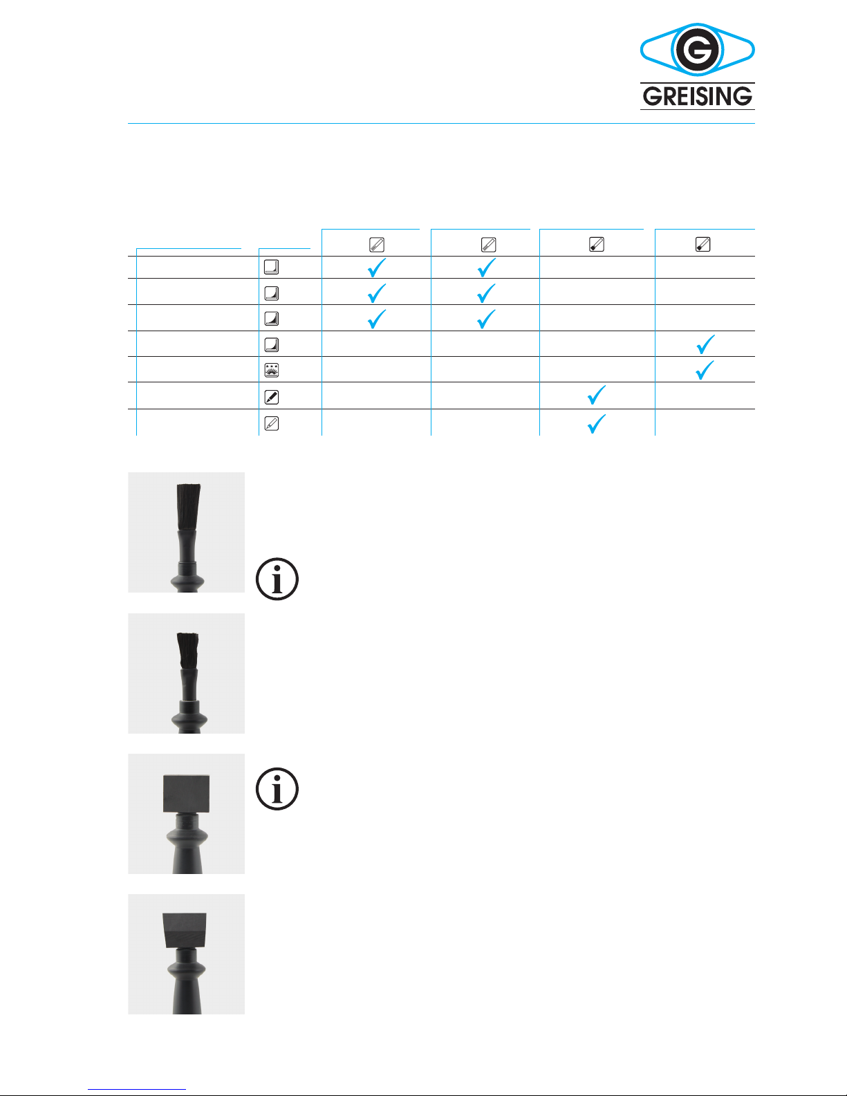
Brush-E Brush-S Brush-P Brush-T Brush-TP
picklinglevel1*
picklinglevel2*
picklinglevel3*
picklinglevel4**
electropolishing
dark marking
light marking
blasting
electrolyte supply
3 FUnCTiOn, MeTHOd OF OPeraTiOn
3.1 FUNCTION
2.3 TRANSPORT, SETTING UP
Please pay attention to the transport instructions on the packaging.
Keepupright.Ifpossible,storevibration-free.
2.3.1 Surrounding conditions
•Temperature
- 5 °C to + 55 °C
•Humidity
Dry, indoors, dew-protected
•To be erected
Dust-free,level,awayfromexplosivegases
• Suitable materials
Allconductivemetalsurfaces
2.4 ACCESSORIES
Thecontentsofthevariousaccessorysetscanbereadinthecurrent
price-lists.Theunitpriceonlyincludesthepowercable.
Operation Manual Clean Marker Brush −Page 8
*withbrushattachment
**withattoolhat

3.2 METHOD OF OPERATION
• electrochemicallypicklingandcleaning
• etchingelectrochemically
• blastingwithglasspearlsoraluminousabrasive
3.3 SAFETY AND MONITORING EQUIPMENT
• 35Amp(1)and4Amp(2)
Aexcesscurrentswitchonthefrontoftheunit6,3Acut-outfuseonthe
rear of the unit (12).
3.5 OPERATING AND DISPLAY ELEMENTS
3.5.1 Front Side, Operating Panel
(1) Safety cut - out 35 Amp
(2) Safety cut - out 4 Amp
(3) Redindicatorlightforsafetycut-out35Amp
(4) Selector switch
(5) Redconnectingsocketfortheworkpiece(earthingcable)
(6) Blackconnectingsocketforthetool(wand)
(7) Green indicator light, showing state of operation
Connecting socket for blasting agent tubing
(8) 6mmtubingforblastingagentexpulsion
(9) 4mmbluetubing
(10) 4mmblacktubing
Operation Manual Clean Marker Brush −Page 9

instructions for use
1
5
8
6
9
7
10
2 3 4
Clean MarKer BrUsH-e
Clean MarKer BrUsH-s
Clean MarKer BrUsH-P
Clean MarKer BrUsH-T
Clean MarKer BrUsH-TP
picklinglevel1
picklinglevel2
electropolishing
dark marking
picklinglevel1
picklinglevel2
picklinglevel3
electropolishing
dark marking
light marking
electrolyte supply
only Brush-P
picklinglevel1
picklinglevel2
picklinglevel3
electropolishing
dark marking
light marking
blasting
electrolyte supply
only Brush-TP
Operation Manual Clean Marker Brush −Page 10
Whenelectro-polishing,materialisremovedfromthesurfaceoftheworkpi-
ecebyspecicelectrolytesusedinconjunctionwithanexternalDCsource.
Thematerialsetfreebytheelectrolyteisnon-pollutingandfollowsunder
atteningconditions.Incontrasttomechanicalremovalprocesses,atte-
ningbyelectro-polishingbeginsinthemicrorangeandincludes,during
longerpolishingperiods,largerstructureswhichareroundedandattened
off on their top surface. During electro- polishing, two different mechanisms
worksimultaneously,oneattenstheuppersurfaceinthemicrorangeand
theotherachievesnedeburringinthemacrorange.
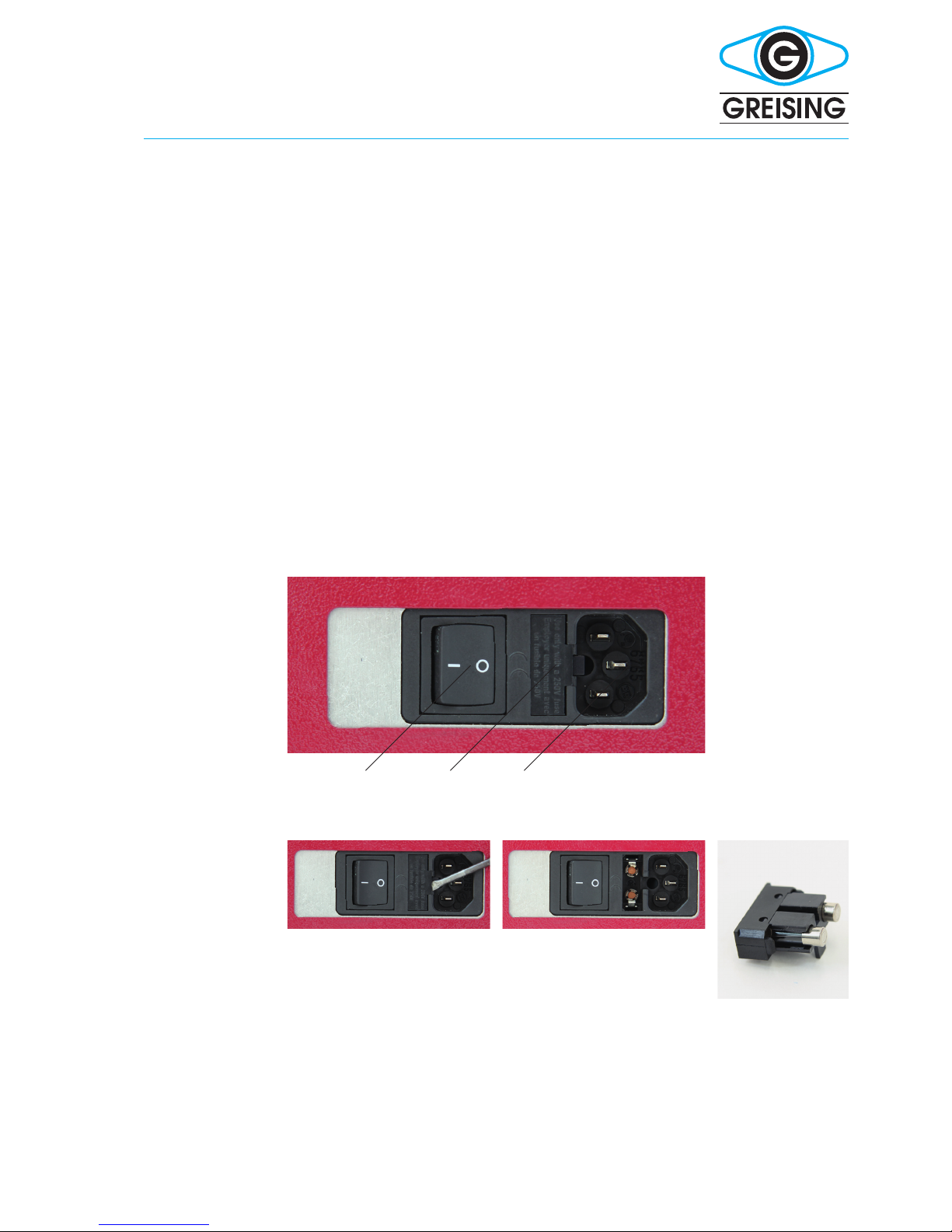
3.5.2 Reverse
(11) Main switch
(12) Fuse6,3Amp
(13) Connectingsocketformainscable
Operation Manual Clean Marker Brush −Page 11
11 12 13
11openap(withscrewdriver)
removefuseslider
exchange fuses

instructions for use
4 TransPOrT, seTTinG UP
4.1 SAFETY REGULATIONS
4.1.1 Temporary storage
Always keep the unit in its outer packaging and in a dry room indoors.
4.1.2 Unpacking
Withoutusingsharptools,removetheouterpackagingcarefully.
Keeptheoriginalpackaging.Alwaysuseitforstoringandtransportingthe
unit.
4.1.3 Putting the machine into operation
• checkthatthemainsvoltageisthesameasthatonthetypelabelandis
the same as the setting
• usingthemainscableconnecttheunittothemainsvoltage
pushtheredcableintotheredconnectingsocket(5)
• fixtheearthingclamptotheredcableandthenontheworkpiece
• pushtheblackcableintotheblackconnectingsocket(6)
• fixtheotherendofthecableintothetoolforlettering/cleaning
• switchontheunitatthemainswitch(11),theyellowlight(7)should
belit,theunitisready
• settheunitasdesired
5 OPeraTinG
5.1 INITIAL OPERATION
Carryoutacheckandinspection,notonlypriortoinitialoperation,butalso
priortoeverysetup.Setuptheunitasdescribedabove.
Workingwithchemicalscanbedangerous.Alwayswearafacemask,
acid-proofapron,gogglesandgloves.WhenusingGreinox1000/2000/
Polish,RapidpleasereadtheSafetyDataSheetsrst(currentlytobe
foundunderwww.greising.com/CleanMarker/Service).
Donotingestthevapoursarising.Shouldtherebeskincontact,washwith
plenty of water.
Operation Manual Clean Marker Brush −Page 12
5.1.1 Unit adjustments for cleaning for Clean Marker Brush devices
selector switch (see page 10)
5.2 CLEANING WITH CLEAN MARKER BRUSH ATTACHMENTS
5.2.1 Tips for maximum cleaning effect
WiththeCleanMarkerbrushattachmentyoucancleaneveninaccessible
parts.Theshortbrushshowsmorepowerfullperformance,thelongbrushis
especiallyforbigareas.Chancethebrushintimetoavoitshortcircuits.
Slag and scale spots can only be removed by blasting
(Clean Marker Brush-T and Brush-TP)
5.2.2 The „Cleaning“ Process
• screwonthebrushattachment
• adjusttheunitaccordingtoChapter5.1.1
• fillabout1cmGreinox1000,2000,PolishorRapidintothewide-neck
containermorecanbefilledintothecontainersforpumpunits
• moistenthetool
• runthetooloverthebloomuntilthesurfaceisclean
To avoid white edges on the work piece: polish the cleaned
work piece with the cleaning cloth supplied, lightly moistened
with water and Neutralyt.
Croping the brush will increase performance.
On level 3 short circuit signs may appear. It may be necessary
to chance down on level 2.
5.3 ETCHING WITH THE CLEAN MARKER (FLAT TOOL)
5.3.1 Tips for maximum etching effect
Everyelectrolytecontainssalts.Dependingonthematerial,thesesalts
canhaveastronglyoxidizingeffect.Extremecleanlinessmustbeusedwhen
handlingthechemicals.Avoidcarry-overofelectrolytesandwashyour
hands frequently. Make sure of good power contact and moist felt. Felt which
istoodryrestrictstheowofpower.Stencilsbecomecloggedwithsaltsand
metalsafterawhile.Theyshouldalsoberinsedandcleanedfrequently.
Electrolytecanalsobeusedforcleaningstencils.Smallsurfacescanbest
Operation Manual Clean Marker Brush −Page 13
A
B
C
D
selector switch
1picklingwithbrush
2picklingwithbrush
3picklingwithbrush*
4picklingwithelectrod*
5 polishing
6darkmarking
7lightmarking*
brushattachment1(A) brushattachment2(B)
marking stencil (C)
+ marking felt 1
marking stencil
60°(D)+cleaningfelt
symbol
*notwithCleanMarkerBrush-E

instructions for use
beetchedbysimplypressingthefeltonthestencil.Largerareasarebest
etchedbystrokingthetoolheadseveraltimesovertheentiresurfaceofthe
stencil.Thistakesbetween1.5and2seconds.Iftheetchingappears
rusty,theneitherdonotusethetoolquitesolongordecreasethevoltage.
Thetoolshouldbeheldatrightanglestotheworkpieceandthewhole
surface used for contact with the stencil.
the electrolyte ows better through the stencil
Donotallowthestenciltobecometoowarmasthiscouldleadtoprema-
turewearandtear.Whenelectrolytevaporisesitleavesresiduesinthe
stencil tissue. In time this reduces the clarity of the etching. Dark, i. e. dirty,
feltsmustbechangedfrequentlyandthelargerthestencil,thequickerthe
felt needs changing.
Theresultsofletteringdependonvariousfactors.Theresultscanvary
dependingonmaterialorwithinamaterialbatch.Testtheletteringfor
qualityonapieceofwastematerialbeforebeginningtowork.Thelettering
canusuallybeoptimisedbyusingvariousparametersandelectrolytes.By
usingswitch(4)youcansetwhethertheletteringshouldbedarkorlight.
The result differs with different materials.
Morematerialisremovedwithlightlettering.Thestencilgetsdirtyvery
quicklyandmustbecleanedmoreoften.
5.3.4 The „Etching (marking)“ Process
• cleanthespottobeetched
• cutoff30mmetchingfelt(t=2mm)fromthe60x2x1000striporfrom
the sheet
• usingthe„O“-ring,fixthefeltpadtothetoolhead
• usingtheselectorswitch(4)settheunittothedesiredsettingforlight
or dark etching
• addenoughelectrolytetothefeltontheundersideofthetoolsothatit
is wet
• positionthestencilinthedesiredpositionontheworkpiece
• usinglightpressureandsmallswivellingmovementsstrokeoverthe
stencilor,ifthestencilissmallenoughtobecoveredbythetoolhead,
thensimplypressdownandmoveslightlytoandfro,holdingthetool
at right handles to the work piece
• 1.5to2secondsshouldbelongenoughtoproduceagoodetching
althoughthisdependsonthematerialtobeetched
• cleanthesurfaceandtheetching
• neutralizethesurfacewithaclothsoakedinNeutralytGN2severaltimes
• thenfinallyconservethesurfaceandtheetchingwithKonservatGK2
There is a special tool head for etchings wider than 30 mm.
Operation Manual Clean Marker Brush −Page 14

Operation Manual Clean Marker Brush −Page 15
5.4 DEALING WITH SHORT-TERM STENCILS
5.4.1 Marking with short - term stencils
•placetheshort-termstencilwiththeblue/greensidefacingyouintothe
typewriter/matrixprinter(withoutribbon)
•typethedesiredletteringontotheblue/greenside
•removetheshort-termstencilandcutittothedesiredsize.
•removethewhiteprotectivepaper
•moistentheuppersideoftheshort-termstencilwithelectrolyte
•putthestencilintopositionontheworkpiece
•pressthetoolheadontothestencilsothatthewholesurfacecoversthe
stencilandmoveitaroundgently
•afterabout1.5to2seconds(dependsonthematerial)theprocess
shouldbefinished
•cleanthesurfacesothatnoelectrolyteremainsontheworkpiece
•neutralizethesurfaceusingaclothsoakedinNeutralytGN2
•conservetheletteringandthemetalsurfacewithKonservatGK2
5.5 CLOSING DOWN THE UNIT
• switchoffatthemainswitch(11)andremovethemainsplug(13)
• dismantlealltheaccessories
• cleanallparts
5.6 BLASTING WITH THE CLEAN MARKER BRUSH-T AND BRUSH-TP
5.6.1 For precision removal of slag and scale spots on welded
seams
Additionalusesare:roughening,cleaning,de-rusting,de-burring,
polishing,mattingandcompactingsmallareas,byusingsuitableblasting
agents,suchasglassparticles,specialalumina,siliconecarbide,walnut
and plastic granulate in the range of 1 −300µ.
5.6.2 Equipping for blasting
The Clean Marker T4 is equipped with a pressurised container holding 0.8 l.
Thejetnozzleisactivatedbytheswitchonthehandle.Thedesiredworking
pressureissetbythepressurecontrollerandcanbereadonthepressure
gauge.Therearetwoboroncarbidenozzlesd=1.2and1.8mmtochoose
from.Toexchangethenozzle,simplyunscrewtheunionringonthenozzle
handlethenexchangetheboroncarbidenozzle.
5.6.3 Setting up the blasting unit
Connectingthetubingontheunit:
• connectblastingtube
6mmtubingforblastingagents(8)
4mmtubing,blue(9)
4mmtubing,black(10)
Screwtheblastingnozzletothetubingusingascrewcap.Using
compressedairtubeconnectthecompressortoconnection

instructions for use
make sure the air is dry, otherwise the blasting agent will
form lumps
Set the desired working pressure on the regulator. The compressed air set
willbedisplayedontheManometer.
max. 7 bar, recommended is 2 −4 bar
air consumption about 150 l /min at 5 bar
Fillblastingagentintothecontainer
make sure the blasting agent is dry
Thelid(15)istobeunscrewedwhenblastingagentislledintothe
container.Usingafunnel,llthecontainerwithblastingagentuptoapprox.
onenger’swidthundertherisingpipeinthemiddleofthecontainer.
Close the container.
Youcanbeginworkbyusingthebuttonontheblastinggun
Blastingstopsbyreleasingthebutton
Onceworkhasbeennished,theunitmustbedisconnectedfromthe
compressed air supply.
during blasting, goggles (face mask), dust mask, breathing
mask and gloves are to be worn
5.6.5 Blasting agent
Asarule,thefollowingtwoagentscanbedeliveredexstock:
•EKS 10:
stronglyabrasive,fastremovingagent–leavesaroughsurface
•MGK 10:
hasamorepolishedeffect–leavesashinysurface
5.7 CONNECTING UP THE AUTOMATIC ELECTROLYTE FEED ON
CLEAN MARKER P AND CLEAN MARKER TP
• plugtheblackplugbelongingtothepumptubingsetintotheconnecting
socket (17)
• pushtheacidtubingsofarintothestainlesssteelconnectionofthebulk-
headstuffingbox(20),thatitcannotfalloutbyitself-pressthesafetyring
(21)atthesametime,holditfirmlyandpushthetubeintotheopening
• pushthe3-polepluginthedrivingpowerconnection(16)andscrewitup
tightly
• unwindasmuchasyouneedoftheacidtubefromtheroller(18)andtipit
into the electrolyte container (19)
Liquidwillonlybefedwhenthebuttononthecleaningheadispressed.
Whenpumping,opentheacidcontaineralittlesothatnegativepressure
cannotbuildupwhentheliquidissuckedupanddamagethepump.On
all Clean Markers equipped with pump the electrolyte is sucked up directly
fromanexternal5/10litrecannister,abottleorawide-neckedcontainer.
Theacidtubingmustthereforebehungintotheelectrolytecontainer.
Operation Manual Clean Marker Brush −Page16
15

6 MainTenanCe
6.1 SAFETY REGULATIONS
Maintenancemayonlybecarriedoutbyanauthorisedperson.Before
beginningmaintenance,switchofftheunitandsecureagainstinadvertent
switchingon,e.g.by„pullingtheplug“.Workmustbeexecutedalongthe
linesprescribedinChapter1„safetymeasures“.
6.1.1 Maintenance and inspection check list
6.2 GENERAL REMARKS
Donotusecleaningagents,metalobjectsorcompressedair.Dustand
glueresiduesmustberemovedwithascrapermadeofplastic.
Dismantle and clean the tool after use. If not, acid could
concentrate to such a degree that it becomes a health hazard.
The supply of power through the cable could also be affected
and the performance reduced.
Intervals controlposition/adviceofmaintenance utilities
daily,beforeusing Checkthedeviceandthestencil/brush
If necessary replace worn parts
daily, after using cleanstencils,toolhead,cableandstainlesssteelworkingsurface
clean stencils:
carefullybetween2ngersinclearwater
cleaning tool head:
unscrewhandlefromcarbonheadandcleanbothinplentyofwater
attention:
usingawrench,securemandrelonthepumptubing
clean unit and cable:
wipe with a moist cloth
a soft cloth,
brush
16
17
18
19
Operation Manual Clean Marker Brush −Page 17
instructions for use
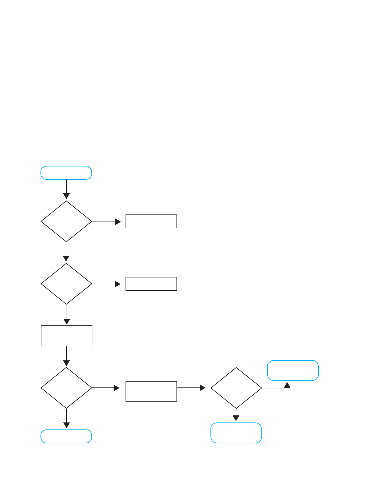
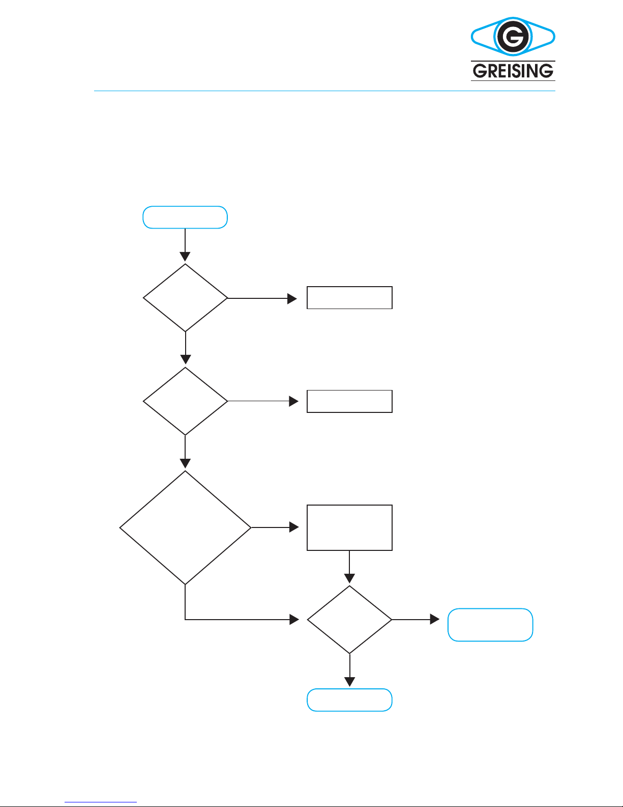
7 disTUrBanCes
7.1 REMOVING DISTURBANCES
7.1.1 Pump does not work
Operation Manual Clean Marker Brush −Page 18
pump does not
work
okay
pressbuttononnozzle
oftubing
yes
switch unit on
connecttubing
(see page 18)
checktubing(3-pole
pin plugs 1 and 3)
ja
replace or repair
suctiontubing
no
no
no
yes
call specialist to
check unit
no
is the unit
switched on?
tubing
connected?
pump is
running
switch
okay?
no
yes
7.1.2 Electrolyte isn´t being pumped
Operation Manual Clean Marker Brush −Page 19
electrolyte isn´t
beingpumped
no
no
call sprecialist to
check unit
switch unit on
see diagram on
previouspage
connecttubingasin
diagram 11
hangthesuctiontube
into electrolyte
no
yes
okay
arethetubes
connected according
todiagram11?(suctiontube
in electrolyte container?)
pump is
feeding electro-
lyte?
unit
switched on?
is the pump
running?
no
yes
yes
yes
yes

instructions for use
7.1.3 Blasting function not working
Operation Manual Clean Marker Brush −Page 20
okay haveunitchecked
byspecialist
yes
yes
connectblastingtube
(3.5.1)
make sure there is dry
compressed air (23)
set operating pressure
on regulator (25)
lldryblastingagent
pressbuttonon
blastingtube
blasting?
bla-
sting
tubingornozzle
blocked?
blasting
agent dry?
cleannozzle
blastingfunctionnot
working
no no no
This manual suits for next models
4
Table of contents


