Coldelite KW-77 User manual

P.O. Box 4069 •Winston-Salem, NC 27115 •336-661-9893 •336-661-9895 (Fax)
KW-77
Counter Model
Whipped Topping Dispenser
OPERATION MANUAL

2
Foreword
Thank you for selecting Coldelite to meet your operation and growing demands.
YourColdelitefreezerhasbeenmanufacturedutilizingthemostadvancedtechnologyand
modern equipment available in the industry. We at Coldelite, take great pride and care in
themanufacturing of eachand every freezer,using onlythe finest componentsavailable, to
provide you with many years of trouble free operation.
Manyyearsofexperienceinthemanufacturing of soft serve dispensing equipment
have guided us in the preparation of this Operation Manual. PLEASE READ IT
CAREFULLY and keep it in an available place for future reference and most of all, follow
theinstructionscarefully.
Onthefollowingpages,youwillfind importantinformationandprocedures,which
describetheproperinstallation,sanitizing,operation,andmaintenanceof yourColdelite
freezer. We feel certain that your compliance with these instructions will assure excellent
performance,trouble-free operation andprofitable business for yearsto come.
All technical data, pictures and drawings contained in this operation manual are not binding on the manufacturer, nor can the
manufacturer be held liable for any modification to the freezer in part or completely. Part Number:

3
Index Page #
Foreword
Part I Installation
A) Uncrating 4
B) Positioning the Machine 4
C) Electrical Requirements 5
Part II Explanation of Controls
A) Electronic Control Panel 5-6
B) Mix Injection Pump 7
C) Texturizer and Dispensing Head 7
Part III Initial Cleaning Procedure 8
Part IV Assembling the Dispenser
A) Assembling the Mix Injection Pump 9
B) Assembling the Texturizer and Dispensing Head 10
C) Assembling the Front Drip Cup 11
Part V Sanitizing the Dispenser 11
Part VI Starting the Dispenser 12
Part VII Operating the Dispenser 12
Part VIII Periodic Cleaning Procedures 13
Part IX Technical Information
A) Refrigeration 13
B) Pump Drive Motor 13
Part X Maintenance
A) Troubleshooting Guide 14-15

4
!! IMPORTANT !!
Failure to closely follow operational and
maintenance procedures may result in damage to
the unit and / or void your warranty. Coldelite
Corporation will not be responsible for any
machine not properly operated or maintained.
Part I – Installation
Before starting this procedure, ensure that the
shipping carton does not show any evidence of
damage due to dropping or mishandling. This
may indicate that the dispenser was damaged
during transit or delivery.
!! IMPORTANT !!
Should the outside of the shipping carton give
any indication of possible damage, state this on
the bill of lading prior to signing. Contact the
freight carrier and request an inspection of
damage. If this procedure is not adhered to, you
will forfeit your rights to file a damage claim
and be responsible for subsequent repair costs.
A) Uncrating the Dispenser
1) The outer shipping carton is secured to the
shipping pallet with strapping. When cutting this
strapping, do so with caution as it may spring out
quickly. After cutting the strapping, lift the
shipping carton straight up and off of the freezer.
2) Remove the protective foam boards and plastic
wrapping from the outside of the freezer.
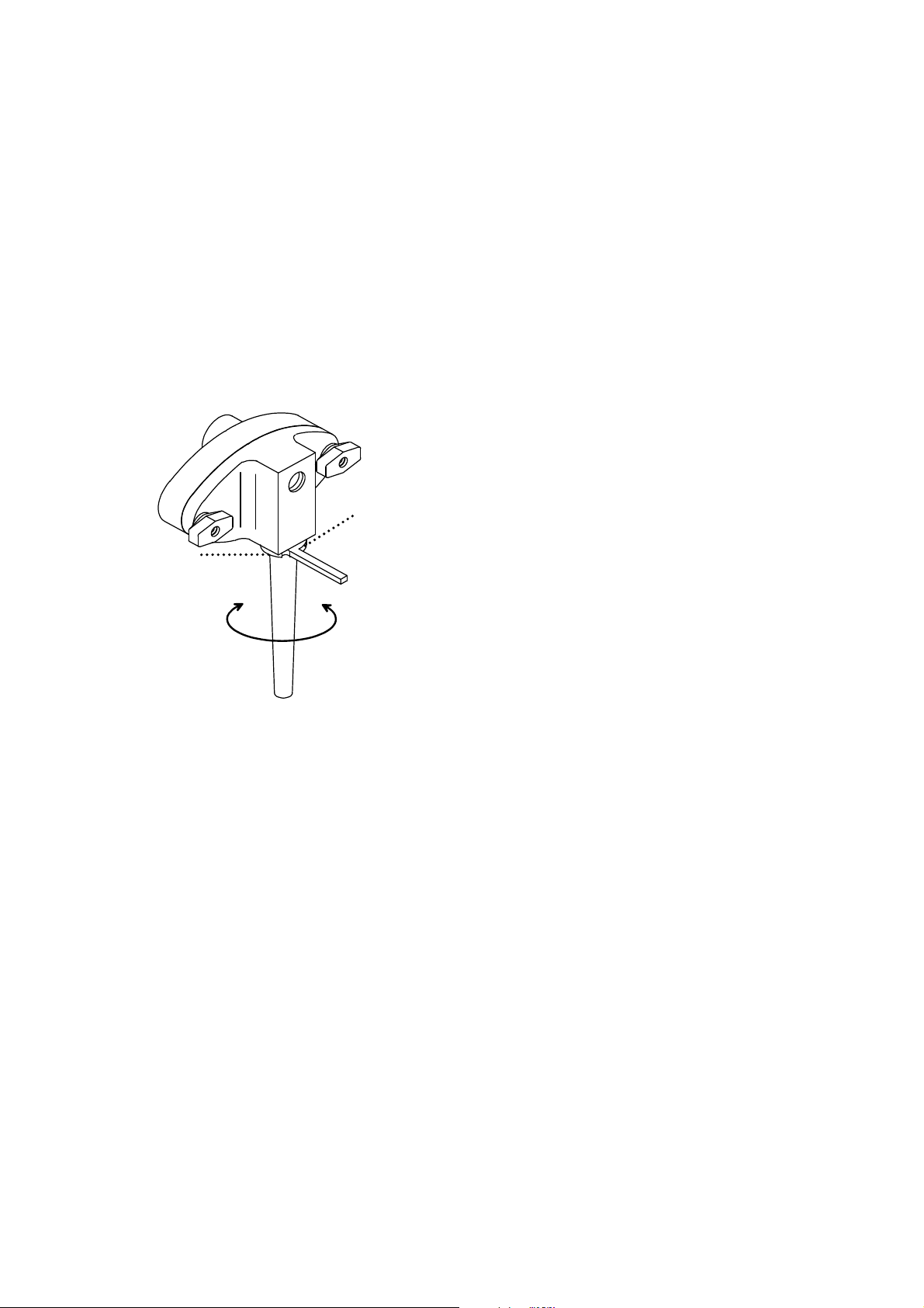
3) Unwind the power supply cord and inspect for
any damage that may have occurred during
transportation. If the cord is damaged or cut in
any way, contact an Authorized Service Agent
before connecting to a power source.
B) Positioning the Machine
After removing the machine from the shipping
pallet, it is now ready to be located in its final
location. Prior to choosing a location keep in
mind that the dispenser should be accessible for
periodic maintenance and have adequate space
for necessary airflow. Please allow 6 inches of
clearance on both sides of the dispenser.
The dispenser must also be level to ensure proper
drainage from the mix tank. To level, place a
level on all corners and shim as needed.
To seal the dispenser to the counter, proceed as
follows:
Determine the exact location you would like to
install the dispenser. Clean the counter top
thoroughly of any dust, dirt or oil.
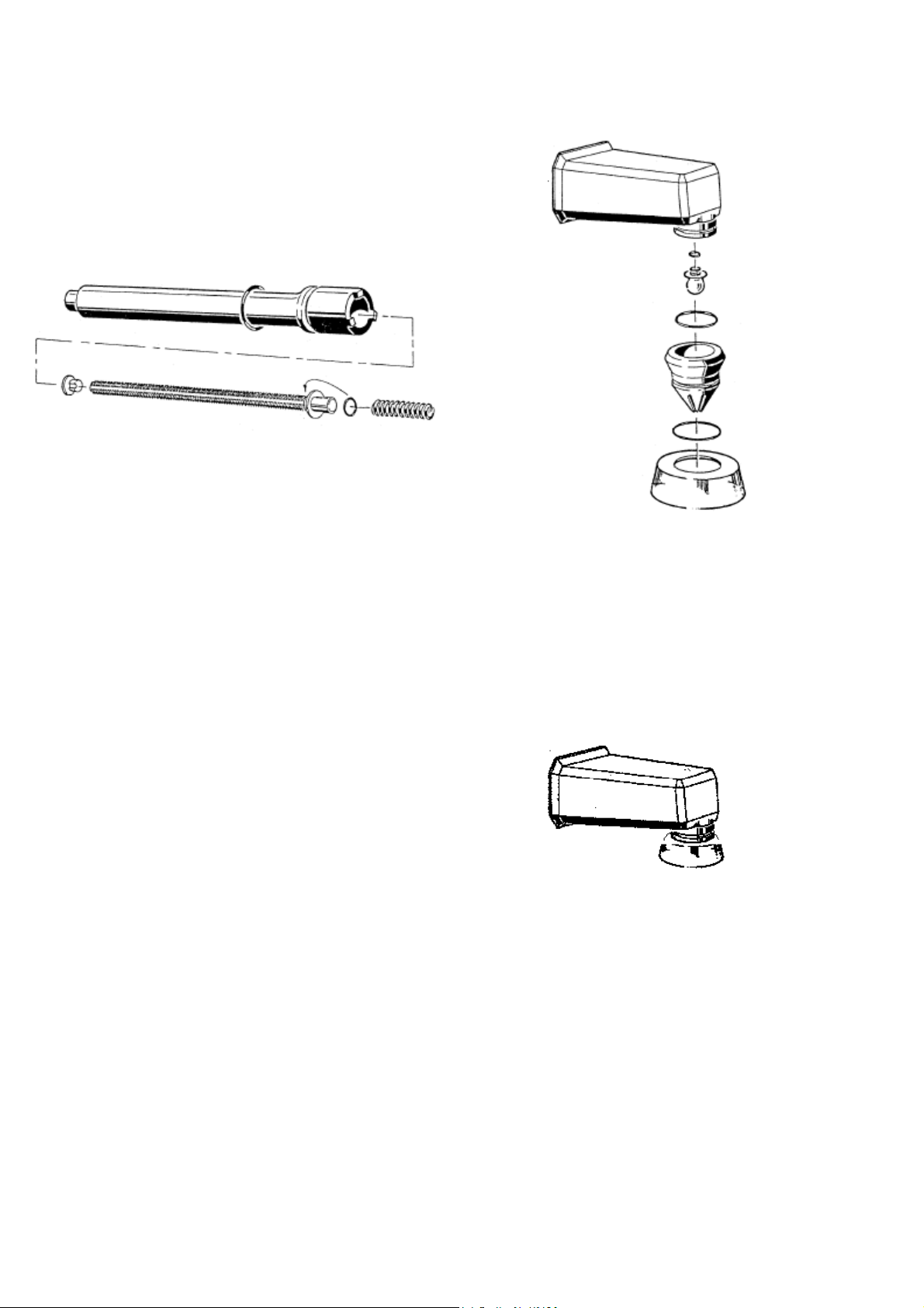
Apply a thin bead (1/4”) of General Electric
RTV-102 (or equivalent) silicone sealant to the
lower mounting rim of the dispenser. (Refer to
Figure 1)
Figure 1
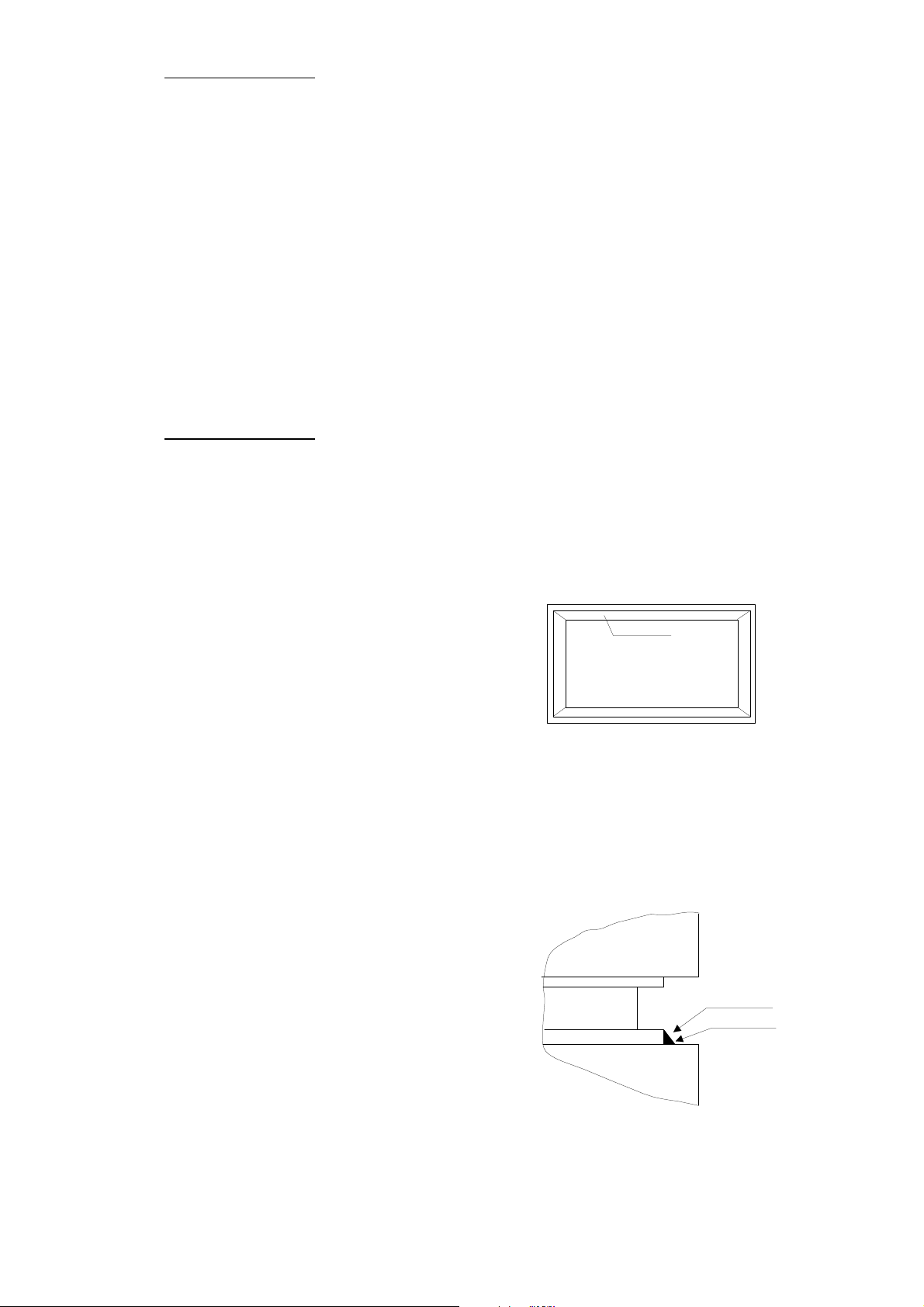
Carefully lift the machine and place on the
counter in the exact predetermined location.
Remove any excess sealant from the base and
counter to create a flawless seam between the
counter top and machine base (Refer to Figure 2)
Figure 2
Machine Bottom
Mounting Rim
Counter
Machine Base
Machine
Counter Surface
Silicone Sealant

5
Allow the sealant to dry thoroughly before
operating the dispenser. Please refer to the sealant
manufacturer specs on the sealant tube.
THE MACHINE IS INTENDED FOR
INDOOR USE
C) Electrical Requirements
!!! WARNING !!!
This machine must be properly grounded.
Failure to provide adequate grounding can
result in severe electrical shock and / or fatal
bodily injury.
This machine is provided with a power cord
connected to the unit. You should have already
inspected the cord for any damages that may have
occurred during shipping. If there is no damage to
the cord, you may plug it into the electrical
receptacle.
For this dispenser, you will need to provide a
dedicated electrical circuit with a rating of
115vac / 60hz / 1phase – 15amperes. This
receptacle should be no farther than 6 feet from
the dispenser and at no times should an extension
cord be used. This electrical circuit must comply
with your local and / or state regulations.
Part II – Explanation of the Controls
A) Front Touch Pad / CPU Unit
The model KW-77 machine is equipped with a
central CPU unit. This unit contains the front
touch pad, which monitors and controls the
functions of the machine. The front touch pad is
also the switching mechanism which operates the
following:
*Refrigeration of the product
*Activates the pump for dispensing
*Set the mix tank storage temperature
*Set the portion size or continuous dispense
mode
*Calibrate the temperature sensing probe
*Displays mix tank temperature
Also contained in the CPU unit is a delay timer
for the compressor. This delay will not allow the
compressor to immediately start, but delay the
start for three minutes. This delay will allow the
internal refrigerant pressures to equalize, which
will minimize high starting loads on the
compressor.
Front Switch Pad
ON OFF 0
°F
+t
sec.
571.2571.1
571.4
571.3
571.5
570.2
570.1

6
You can set the portion time, from 1 to 9
seconds, by pressing the portion adjustment
button (#571.5). To de-activate this mode, press
the portion control button (#571.4) which will
allow for normal dispensing of the product.
Portion Time
Indicator - #570.2
This display will indicate the number of seconds
of dispensing in the portion control mode. When
in the normal dispense mode, a horizontal dash
will appear.
Portion Adjustment
Button - #571.5
When in the portion control mode, this button
will set the portion dispensing time from 1 to 9
seconds.
Dispense Switch -
#571.3
In the normal operating mode, the unit will
dispense product while this button is pressed and
held. While in the portion control mode, the unit
will dispense product only for the set portion time
when this button is pressed.
To continuously dispense product, press and hold
this dispense button (#571.3) and while holding
in, press the portion adjustment button (#571.5).
This will lock in the continuous dispense mode.
To return to the normal operating mode and stop
dispensing product, simply press the dispense
switch button #571.3.
OFF 0
ON Power ON Button -#571.1
Pressing this button will illuminate the front
temperature display and start the compressor
timer. With power on, you may also activate the
dispense button.
Power OFF Button - #571.2
Pressing this button will disable all of the machine
functions. The front display will also not be
illuminated.
Mix Tank Temperature
Display - #570.1
When the Power ON button is activated, the mix
tank temperature will be displayed. Initially, the
temperature displayed will be ambient temperatu-
re. After the compressor starts
(Three minute delay), the tank temperature will
begin to cool down. The compressor will continue
to cool the storage tank until the preset holding
temperature is reached. This temperature drop
may take a few hours before stabilizing. The
machine will continue to hold at the set tempera-
ture until turned off.
Portion Control Activation
Button – #571.4
This switch is used to activate or de-activate the
portion control mode. To activate, press this
button one time. In the portion time indicator
(#570.2) you will see a number. This indicates the
number of seconds the pump motor will run when
the dispense button is pushed. By activating this
mode, you are able to dispense exact portions
from the machine each time product is dispensed.
°F
+
t
sec.

7
B) Mix Injection Pump
Your Coldelite whipped topping dispenser is
equipped with a mix injection pump. This mix
injection pump injects air into the liquid mix
prior to dispensing. This pump has two internal
gears that are driven by a pump drive shaft. This
drive shaft couples with the pump motor through
a pulley and a belt.
The mix injection pump runs whenever the pump
drive motor is turning. To regulate the amount of
mix being dispensed, pivot the pump suction tube
either to the right (less mix/more air) or to the left
(more mix/ less air). (Refer to figure 3)
Figure 3
The air intake is through the front two holes of
the pump cover. Since the two air inlet holes are
fixed, the air intake is constant. To adjust your
overrun (yield) you must regulate the amount of
mix being pumped. The mix pump suction tube
will change the orifice size on the tube to allow
either more or less mix to be pumped.
You will also have to adjust your pump suction
tube orifice setting depending on your product
viscosity and texture desired.
The “Normal” operating position for the suction
tube on this dispenser is either one position to the
left, center, or one position to the right of center.
C)Texturizer and Dispensing Head
The texturizer and dispensing head are also
important parts used to dispense whipped product
from this machine.
The texturizer is used to whip the product that is
pressurized by the mix injection pump. The
texturizer consists of a stainless steel rod
enclosed inside a clear plastic tube. The
texturizer and tube are connected to the pump
cover on one end and the dispensing head on the
other end. The pressurized liquid is pumped
through the channeled texturizer, which whips
the product. The whipped product is then
transferred to the dispensing head and dispensed.
The dispensing head is made of high impact
thermo-plastic. This dispensing head is secured
to the machine by two pins attached to the
refrigerated front extension. To remove the
dispensing head, simply rotate the head counter
clockwise ½ a turn while pulling straight out.
Attached to the head is a pattern nozzle and
splashguard. These parts are secured to the
dispensing head with rubber orings.
min
max

8
Part III – Initial Cleaning Procedure
!! IMPORTANT !!.
This is a new machine and although clean, it must
be completely disassembled, washed and sanitized
before adding fresh product. Please proceed as
follows:
Remove the mix tank cover and spare parts items
packed inside the mix tank. The spare parts kit will
include: spatula, cleaning brushes, sanitary
lubricant, oring removal tool, sanitizer packets,
spare orings and seals, and operation manual. Place
these items in a convenient place for future
reference.
Helpful Suggestion: Before proceeding with the
disassembly of the freezer, we recommend the use
of a clean plastic pan or pail to place the removed
parts into. This will minimize the possibility of
misplacing or damaging these components.
You can now start to disassemble the dispenser’s
parts for cleaning. First remove the dispensing head
assembly by rotating counter clockwise and pulling
straight off the refrigerated extension.
Remove the texturizer and outer tube by sliding
straight out of the front of the refrigerated nozzle.
Remove the mix pump assembly by rotating
clockwise until the hook stud on the rear of the
pump disengages from the pump hub. After
disengaging, slide the pump away from the rear of
the machine and out of the mix storage tank.
Remove both the mix tank drain plugs from both
the mix tank and front panel.
The machine is now completely disassembled and
the removed parts must now be washed, rinsed, and
sanitized. Using the oring removal tool provided in
the spare parts tool kit, remove all of the orings
from their assigned locations on the dispensers
components.
Wash the removed machine parts in luke warm
(80-90 F) water and mild non-foaming detergent.
Scrub each of the parts with the cleaning
brushes provided in the machines spare parts
kit.
!! IMPORTANT !!
DO NOT use hot water on any of the plastic
parts as this may result in damaging these parts.
Using your three-tank sink, wash rinse, and
sanitize all of the disassembled machine parts.
Mix the Stera Sheen – Green Label sanitizer to
a solution of 100ppm concentration with warm
water. Allow the parts to soak in the sanitizing
solution for 3-5 minutes before removing.
Allow the parts to air-dry on the clean, sanitized
counter at the end of the sink. DO NOT towel
or sponge dry these parts.
4) Air Dry
3)Sanitize
1)Wash
2)Rinse

9
Part IV -Assembling the Dispenser
Once all of the parts have been washed, rinsed and
sanitized, the dispenser is ready to be assembled.
A) Assembling the Mix Injection Pump
To re-assemble the mix injection pump you must
first locate the parts needed to complete this
assembly. (Refer to figure 4 )
Figure 4
After locating the parts, install the rubber orings.
Lightly coat these with the sanitary lubricant
provided with your dispensers tool kit.
Next apply a light coat of lubricant to each side
and center of the mix injection pump gears.
DO NOT lubricate the gear teeth as this adds no
protective lubrication to the pump. Install the
lubricated gears into the mix pump body.
Lightly lubricate the mix pump shaft seal on both
the inner and outer surfaces. Install this seal into
the rear of the mix pump body.
Install the pump drive shaft into the rear of the
mix pump body ensuring that it is engaged into the
pump drive gear.
Carefully install the pump body into the mix
storage tank. Rotate the pump onto the pump
locking hub ensuring that pump hook stud
engages onto the hub locking pin. Rotate the
drive gear until the shaft engages into the rear
drive coupling. The gear will be completely
enclosed into the pump body if installed properly.
If the gear continues to protrude from the pump
body, continue to rotate while pressing into the
pump body until successful.
Next, install the mix suction tube and spring into
the pump cover well. Rotate the suction tube until
it is locked into place with the lever pointing
away from the rear of the pump.
Install the large oring into the mix pump body
and lightly lubricate. Next, install the pump cover
assembly onto the installed mix pump body.
Secure the mix pump cover to the mix pump
body with the two metal retaining knobs.
NOTE: Hand tighten these knobs only. DO
NOT use any tools to tighten or pump
component damage may occur.

10
B) Assembling the Texturizer and Dispensing
Head
With the mix pump assembly installed, you are
now ready to assemble and install the texturizer
and dispensing head. First locate the parts needed
to assemble the texturizer. (Refer to figure 5)
Figure 5
Lightly lubricate the orings and texturizer seal
and assemble onto the texturizer and tube. Slide
the metal texturizer into the outer plastic
texturizer tube, seal end first. The texturizer and
seal should slide easily into the outer tube.
Slide the texturizer tube assembly into the
refrigerated front extension of the dispenser. The
front of the plastic texturizer tube must
completely engage into the mix injection pump
cover. Slide the texturizer spring onto the metal
texturizer, which protrudes, from the front
refrigerated nozzle.
The texturizer tube is now completely assembled
and installed into the dispenser. You are now
ready to assemble and install the dispensing head.
First locate the parts needed to assemble the
dispensing head. (Refer to Figure 6)
Figure 6
Lightly lubricate and install the orings onto the
correct parts. Install the diffuser plug into the
center hole of the dispensing head. Next install
the pattern nozzle over this plug and fasten onto
the dispensing head. Install the splashguard onto
the outside of the pattern nozzle as shown below.
You are now ready to install the head assembly
onto the dispenser. To do this, slide the
dispensing head onto the front refrigerated nozzle
with the pattern nozzle pointing up. Slide the
dispensing head assembly onto the nozzle until
the stopping point is reached. Turn the head
assembly clockwise until it locks into position
and the nozzle is pointed straight down.
The dispensing head assembly is now installed.
You can now install the front drip cup assembly.

11
PartV – Sanitizing the Dispenser
The dispenser is now assembled but must be
sanitized prior to filling with fresh mix.
Mix one gallon of sanitizing solution in a clean pail
with warm water (80-90 degrees F). Using the Stera-
Sheen (Green label) or equivalent sanitizer, follow
the manufacturer’s directions on the packet to ensure
a 100ppm-solution concentration is achieved.
Pour the sanitizing solution into the mix storage
tank. Using the largest cleaning provided with the
tool kit, brush clean all of the surfaces of the mix
storage tank.
Press the “Power ON” button
on the front touch pad.
Place a container or pail under the dispensing head.
Now press the product dispense button on the front
touch pad. This will run sanitizing solution through
the texturizer tube assembly and dispensing head,
sanitizing all product contact surfaces. Dispense
approximately 6-8 ounces of sanitizing solution, then
release the dispense button.
Press the “Power OFF” button
on the front touch pad, turning
the machine to the off mode.
Allow the remaining sanitizing solution to remain in
the dispenser for 2 – 3 minutes.
To drain the remaining sanitizing solution from the
dispenser, place a pail under the front drain plug next
to the front panel. Remove the front drain plug, then
slowly remove the hook drain plug from inside the
mix tank. The sanitizing solution will now drain
from the dispenser. Using the sanitized spatula
provided in the spare parts kit, direct the remaining
sanitizing solution to the drain hole in the mix tank.
After all of the sanitizing solution has drained from
the dispenser, reinstall the hook drain plug and front
drain plug unto the machine.
You are now ready to fill the dispenser with fresh,
liquid mix.
Part VI – Starting the Dispenser
C) Assembling the Front Drip Cup Bracket
Locate the parts needed to assemble the front drip
cup, bracket and hopper plugs. (Refer to figure 7)
Figure 7
Lightly lubricate the orings and install onto the
correct parts. Slide the drip cup holder onto the
metal drip cup-mounting bracket. Install the
metal bracket onto the front retaining screw
located on the lower front panel. While holding
the metal drip cup bracket, install the front drain
plug into the front drain tube of the dispenser.
This drain plug will also hold the front metal
bracket onto the dispenser. Place the drip cup and
cover into the drip cup holder. The front drip cup
is now completely assembled.
Install the inside drain plug (hook) into the mix
storage tank drain hole.
The machine is now completely assembled and
ready to be sanitized and started.
OFF 0
ON

12
Only after the machine and all of its components
have been cleaned and sanitized should you start
the dispenser and serve product.
To start the dispenser, press the “Power ON”
button on the front touch pad. This will start the
three-minute delay timer for the compressor.
Pour your liquid mix into the mix storage tank.
You must not over fill the mix tank with mix.
The maximum quantity of mix should NEVER
exceed 6 quarts. The minimum quantity of mix
should no be less than 1 quart of liquid mix.
(Refer to figure 8)
!! IMPORTANT !!
NEVER use mix that is semi frozen or not
completely dissolved (if from powder) since
this can cause damage to the mix injection
pump and its components.
Figure 8
Place a cup under the dispensing nozzle and press
the dispense button on the front touch pad for 10
seconds. Whipped product should dispense at this
time and any remaining sanitizer will be chased
out of the machine, discard this product.
Part VII – Operating the Dispenser
After completing the “Starting the Freezer”
procedures, you may now start dispensing
whipped product.
To dispense product,
press the “Dispense” button
on the front touch pad
This dispenser has an “Overrun” adjustment,
which allows the operator to adjust the product to
achieve the desired consistency. This adjustment
lever is located on the mix injection pump suction
tube. This adjustment will regulate the amount of
liquid mix being pumped through the mix pump.
The air being pumped is constant, and is injected
through the front two holes on the mix pump
cover.
To dispense a light fluffy product (less mix), set
the lever to the right of center. If a heavier,
creamy product (more mix) is desired, set the
suction tube to the center or left of center
positions. (Refer to Figure 9)
Figure 9
min
max
Maximum
Minimum

13
IX – Technical Information
Model KW-77 – 120Vac/60Hz/Air
A) Refrigeration
Compressor MFG. – Danfoss
Horsepower – 0.17
FLA. – 1.1 amps
Locked Rotor Amps – 11.4 amps
Low Side Pressure – 14 psig
High Side Pressure – 140 psig
Condenser Cooling – Air
Refrigerant Type – R134a
Refrigerant Amount – 3.5 ounces
Metering type – Capillary tube
Condenser Fan Motor
Horsepower – 0.01
Full Load Amps – 0.88
RPM – 3000
B) Pump Drive Motor
Motor MFG. – General Electric
Motor Type – CSIR / ODP
Horsepower – 0.5
Full Load Amps – 8.8
Overload Type – Manual / Internal
Reset Location – Rear of motor casing
Part VIII – Periodic Cleaning
Procedures
Cleaning and sanitizing schedules for your
dispenser are determined by your local Health
Department and / or Department of Agriculture
and must be followed accordingly. Check with
your local organization prior to determining your
cleaning schedule.
After determining your schedule, proceed as
follows:
Press the “OFF button”
On the front touch pad.
To drain the remaining liquid mix from the
dispenser, place a pail under the front drain plug
next to the front panel. Remove the front drain
plug, then slowly remove the hook drain plug
from inside the mix tank. The liquid mix will
now drain from the dispenser. Using the spatula
provided in the spare parts kit, direct the
remaining liquid mix to the drain hole in the mix
tank. Replace the hook drain plug into the mix
tank drain hole.
Fill the mix tank with 6 quarts of luke warm (80-
90F) water and a non-foaming dish washing
detergent solution. Press the “Power ON” button
on the front touch pad. Press the “Dispense”
button on the front touch pad, and dispense
approximately 12 ounces liquid.
Press the “Power OFF’
button on the front
touch pad.
To drain the remaining soap solution from the
dispenser, place a pail under the front drain tube
next to the front panel. Slowly remove the hook
drain plug from inside the mix tank. The soap
solution will now drain from the dispenser. Using
the spatula, direct the remaining soap solution to
the drain hole in the mix tank.
With the machine completely drained, you must
now disassemble, clean, sanitize and reassemble
your dispenser. Proceed and follow the
instructions as described in Part III of this
manual, Initial Cleaning Procedure.
OFF 0
OFF 0

14
Part X – Maintenance and
Troubleshooting
Your Coldelite dispenser has been designed,
engineered, and manufactured to achieve high
performance and long durability. The life
expectancy of any machine depends not only on
the quality of engineering, and components used,
but also on the basic maintenance procedures.
It is important for you to become familiar with a
few of the basic operating procedures.
·Only remove orings with the oring extractor
provided in the machine spare parts kit.
·Clean and sanitize the freezer in accordance
with the instructions in this operation manual.
·Lubricate all orings and seals as instructed.
·The wearing or the improper cleaning of the
Mix Pump Shaft seals will result in product
leakage into the rear of the machine. Check
frequently and replace seals when necessary.
·Replace any oring that is leaking or damaged.
·When all of the spare parts supplied in the spare
parts kit are used, re-order immediately. Do not
wait until the part is urgently needed or causes
the machine to be inoperative without it.
·During the washing, cleaning and sanitizing
procedures, operate the machine in the “Power
ON” mode as little as possible. This will
minimize component wear on the dispenser.
·When removing and installing the dispenser
parts, handle these with care. DO NOT drop or
bang together as this will damage the parts and
affect the dispensers performance.
·NEVER use HOT WATER when washing,
cleaning, or sanitizing your freezer or its parts.
ALWAYS use luke warm water (80-90F).
!! IMPORTANT !!
Your machine is Air Cooled, and its efficiency
depends on a clean air-cooled condenser. The fins
of the condenser must be straight and cleaned a
minimum of every one or two months. Prior to
cleaning the air condenser, place the machine in
the OFF mode and disconnect power to the
dispenser.
The following is a recommended wearable parts
replacement schedule. This is for normal
operation of the freezer and will vary based on
the volume and type of product served as well as
operational and cleaning procedures.
Replacement Schedule
Orings and Seals – Every 6 months or as needed
Drive Belt – Every 2 years or as needed
Mix Pump Gears – Every 3 years or as needed
Pump Drive Bearings – As needed
Plastic Parts - As need when leaking, scratched,
or broken
Rebuild Mix Pumps – Every 5 years or as needed
Electrical Components – When malfunctioning.
!! IMPORTANT !!
Prior to opening any of the machines outer
panels, place both sides in the STOP / OFF
mode and disconnect the machines power
supply. Failure to do so can result in serious
injury and or death.

Trouble-shootingGuide
Problem Encountered
1) With power ON, no product
dispensesFrommachine
2) Product dispenses poorly
whipped and / or wet looking
3) Product dispenses slowly or
intermittently
4) Does not dispense product when
Dispense Button pressed and
motor runs
5) Mix does not stay cool, but
machineisdispensingand running
6) Dispense button does not
activate pump drive motor
7) No switch functions working or
touch pad illumination
Suggested Remedy
A) Tighten knobs.
B) Disassemble and brush clean, sanitize and reassemble
C) Replace pump gears.
A) Drain machine, clean, sanitize and restart with fresh mix.
B) Adjust suction tube to a smaller size hole (Set to right).
C) Drain machine, clean, sanitize and restart with fresh mix.
D) Replace plastic texturizer tube.
A) Refill mix tank with liquid mix.
B) Adjust suction tube lever to larger hole size.
C) Replace and lubricate ALL orings and seals.
A) Call a Coldelite Authorized Service Company
B) Call a Coldelite Authorized Service Company
A) Call a Coldelite Authorized Service Company
A) Check power supply
B) Call a Coldelite Authorized Service Company
Possible Cause
A) Pump knobs loose.
B) Texturizer clogged.
C) Pump Gears Worn.
A) Liquid mix has separated.
B) Suction hole size too large.
C) Pump and/or texturizer clogged.
D) Texturizer tube worn.
A) No liquid mix in tank.
B) Suction tube hole too small.
C) Orings / seals worn or damaged.
A) Pump bearing locked up
B) Pump drive belt worn or broken
A) Refrigeration Problem
A) Switch or motor problem
A) No power coming to the machine
B) Switch or transformer problems
Table of contents
Popular Beverage Dispenser manuals by other brands

Maytag
Maytag SkyBox MBV1976AA manual

Cornelius
Cornelius VIPER E Operator's manual

Multiplex
Multiplex N2-Fusion ND21TS00 Installation, operation & maintenance manual

Follett
Follett U300 Series Installation, operation and service manual

Bunn
Bunn iMIX-3S Illustrated parts catalog

Perlick
Perlick DP32 Installation and operation instructions

Primo Water
Primo Water hTRIO B380K quick start guide

Cornelius
Cornelius Remcor TJ200 Operator's manual

Crathco
Crathco Crathco 3341 Operator's manual

Multiplex
Multiplex WELBILT Blend-In-Cup MB-8-1PP6 Installation, operation and maintenance manual

Vinotemp
Vinotemp VT-WINEDISP2 owner's manual

Cornelius
Cornelius Enduro 200 Operator's manual