manuals.online logo
Brands
  1. Home
  2. •
  3. Brands
  4. •
  5. Concept2
  6. •
  7. Enclosure
  8. •
  9. Concept2 995200PE User manual

Concept2 995200PE User manual

Revision 1.21 October 2007. 1
CONCEPTCONCEPT
CONCEPTCONCEPT
CONCEPT
Small Low Profile Powered Enclosure.
P/N: 995200PE
INSTALLATION MANUAL
Overview
The Small Low Profile Powered Enclosure can be used wherever Battery-backed 12V supplies are required to power Concept
Modules and associated devices such as Detectors, Readers and Auxiliary Devices such as Strobes, Sounders, Locks, etc.
The Box is designed to house the Transformer, Power Supply PCB, 7AH Battery and a single B1, B2 or C size Concept Module.
e.g. 1 Door/2 Door Access Module, Mini Expander, Analogue Module or LAN Isolator. The Power Supply features a high
reliability design that offers unconditional stability, and has been designed and tested for compatibility with Proximity readers.
When used with a 2 Door Access Module or Mini Expander, a single Ribbon cable may be used (P/No: 605050 or 605049) to
connect the Power Supply to the Module. When this option is used with the Mini Expander, Zones 7 and 8 are connected to the
AC Fail and Low Battery alarm outputs of the Power Supply and cannot be used as general purpose Zone Inputs.
ElectricalSpecifications
Input: 16VAC @ 2.5A. Output Voltage: 13.8V DC +/-2%, up to 2A.
(From Transformer provided) Maximum Output Current: 2 Amps.
Switching Frequency: 50 kHz. approx. Output Ripple: 100mV RMS max. @ Iout = 2A.
Conversion Efficiency: 80%. approx. Load Regulation: +/- 100mV @ Iout = 0.1A to 2.0A.
“Low Battery” trigger voltage: 11V DC. Battery capacity: 12V 7AH Sealed Lead Acid.
Mechanical Specifications
Dimensions: Length: 252 mm. (Allow 20mm at bottom of case for Mains cable entry)
Width: 358 mm. Depth: 83 mm.
Weight: 7.2 kg. (Includes mains transformer, battery and cover)
Power Supply PCB dimensions: 95mm X 80mm X 50mm high.
Operating Environment: 0º to 40º Celsius (Ambient) 15% to 85% Relative humidity (non-condensing)
Powered Equipment Box Parts List
- 2A Power Supply PCB assembly and Mains Transformer mounted in Metal enclosure.
- PCB Mounting plate. - Installation Manual. (This document)
- Installation Kit containing:
- 2 x 2 Way Plug on Screw Terminals. - Battery connection cable. (P/No: 605051)
- 1 x 8 Way Plug on Screw Terminal. - 1 x 4A Fast Blow fuse. (Spare)
- Tamper Switch and Metal bracket. - 1 x 1.0 Amp Slow Blow Mains fuse. (Spare)
- 2 x 6.3mm Tamper switch connectors. - 15 x PCB Mounting Clips. *
- 1 x 10 way Ribbon cable -20cm. (P/No: 605050) * - 15 x M3 screws. *
NOTES: 1) * These items not included in installation kit if this product is supplied with a Concept Module already fitted.
2) If the enclosure and Battery are to be installed in any way other than that shown in Diagram 3 on Page 3, the
optional Battery retaining bracket (P/No: 926005) is required.
Designed & manufactured in Australia.
Due to on-going product development this manual is subject to change without notice.
© 2004 - 2005. Inner Range Pty. Ltd. Part No: 635200PE
CONCEPTCONCEPT
CONCEPTCONCEPT
CONCEPT. Small Low Profile P. Small Low Profile P
. Small Low Profile P. Small Low Profile P
. Small Low Profile Powered Enclosure.owered Enclosure.
owered Enclosure.owered Enclosure.
owered Enclosure. Installation Notes.2
Installing the Small Low Profile Powered Enclosure.
ElectricalAC Mains Power connection.
In countries where the module is supplied without a mains power cord, a suitable mains power cord for connection to the 240V
AC Mains supply must be installed by a suitably qualified electrician or technician.
1. Strip 30mm of the sheath from the end of the power cord. Trim 5mm from the ends of the Active and Neutral conductors so
that the Earth conductor remains slightly longer.
2. Strip 5mm of insulation from each of the conductors and feed at least 100mm of the power cord through the AC mains cable
entry hole in the bottom of the chassis.
3. Terminate the power cord in the terminal and fuse block as illustrated in Diagram 1 below. Note that the Active wire is
always connected into the termination nearest to the fuse.
4. Determine the appropriate length of power cord between the terminal block and the cable entry hole. (Approx. 100mm)
Working from the bottom of the chassis, fit the plastic grommet (supplied) around the power cord and apply pressure to both
sides of the grommet to clamp the cable. The grommet can now be inserted into the AC mains cable entry hole.
IMPORTANT NOTE: An AC Mains socket-outlet shall be installed near the equipment and shall be easily accessible for
connection of the mains power cord.
Transformer
input connection.
Neutral
Earth
Live (Active)
Diagram 1.
25mm
Mounting the Unit. See Diagram 3 on the following page.
1. Installation environment should be maintained at 0º to 40º Celsius and 15% to 85% Relative
humidity (non-condensing)
2. The enclosure must be secured to a flat, vertical surface using fasteners through the four
“keyhole” mounting holes in the chassis. We recommend mounting the enclosure with the
Mains Cable entry and Transformer at the bottom as shown in Diagram 3.
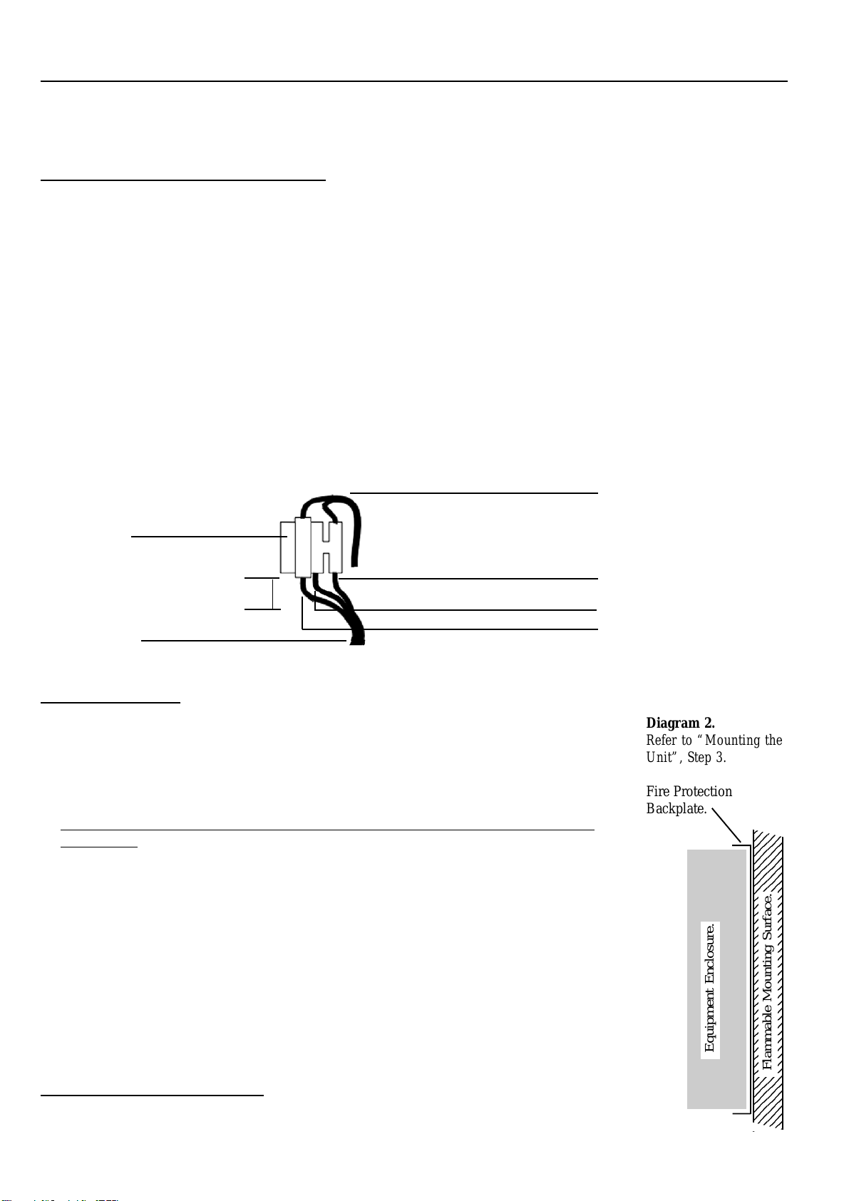
3. When mounting this product onto flammable surfaces, a fire protection backplate MUST BE
INSTALLED. (See Diagram 2) Any Conduit entry points that have had the knockout
removed but will not be used, must also be resealed using 25mm Conduit Plugs.
4. Fit the tamper switch into the tamper switch bracket. Install this assembly by placing the
tamper switch plunger in the hole provided in the base, and the tongue on the bracket through
the slot provided in the lip in the top of the chassis.
5. The Battery is normally installed in the bottom of the enclosure. (See Diagram 3) An
optional Battery retaining bracket (Part Number: 926005) can be used if the enclosure is not
mounted as recommended in Step 2.
6. The metal chassis is electrically earthed and the Circuit Board Assembly is electrically
isolated from the chassis. When mounting and wiring the Module, the Installer must ensure
that this isolation is maintained.
Connecting Power to the PCB. See Diagram 3.
1. The connection between the AC mains transformer output (A) and the “AC” Input
connections on the PCB (B) is pre-wired in the factory.
Fuse. 1.0 Amp
Slow Blow
M205 (20mm)
AC Mains cable.
1234
1
23
4
1
23
4
1
23
4
1
23
4
1
23
4
1
23
4
1
23
4
1
23
4
1
23
4
1
23
4
1
23
4
1
23
4
1
23
4
1
23
4
1
23
4
1
23
4
1
23
4
1
23
4
1
23
4
1
23
4
1
23
4
1
23
4
1
23
4
1
23
4
1
23
4
1
23
4
1
23
4
1
23
4
1
23
4
1
23
4
1
23
4
1
23
4
1
23
4
1
23
4
1
23
4
1
23
4
1
23
4
1
23
4
1
23
4
1234
Flammable Mounting Surface.
Diagram 2.
Refer to “Mounting the
Unit”, Step 3.
Fire Protection
Backplate.
Equipment Enclosure.
Revision 1.21 October 2007. 3
Connecting the Battery to the PCB. See Diagram 3.
1. Place the battery into position. If required, fit the optional Battery retaining bracket by inserting the tab at the Left Hand end
of the bracket into the slot provided near the Mains Transformer. Insert the tab at the Right Hand end of the bracket into the
other slot by gently pushing inwards and down on the side of the bracket.
2. Connect the supplied Battery Cable between the “+” and “0V” connections of “TB3” on the PCB (C) and the Battery
terminals (D), observing correct polarity.
Fitting the Cover.
In order to comply with regulations, the cover must be fitted and the screw provided to fix the cover to the chassis must be
tightly secured.
Power Supply connection details. (Refer to diagrams on page 4)
Links:
JP2 No longer fitted.
(If this Link is fitted [ie on an older board] a LOW state on the “PSDOWN” input will enable the Power Supply)
R20 R20 can be cut out of the PCB to reduce the current limit to 1.0 Amp.
Connectors:
TB1 16.5V 2.5A AC Transformer input connections.
TB2 13.8V DC Output, alarm outputs and control input. See page 4 for details..
TB3 12V 7AH Battery connection.
X3 Direct ribbon cable connection to certain Modules. e.g. Mini Expander or 2 Door Access Module (Type 2 or later)
-Duplicates all connections on TB2. ( Part Number: 605049 [40cm] or 605050 [20cm] )
Fuses:
F1 AC Input Protection Fuse (4 Amp Fast Blow)
F4 Battery Protection Fuse (4 Amp Fast Blow)
Note: Blown Fuses must always be replaced with a fuse of the same type and rating.
LEDs:
ACFAIL Indicates AC Fail condition.
ON Indicates Power Supply output is present.
REV BATT Indicates Connections to Battery are wrong polarity and Fuse F4 is blown.
Tamper switch & bracket.
Mounting Holes. x 4
Cable access cutout in base.
Power Supply Output &
Control connections.
Battery connections.
16.5V AC Power connections.
AC Mains Transformer.
AC Mains Terminal block &
fuse.
12V, 7AH Battery.
Mains Cable entry point &
Grommet
Diagram 3.
B
A
C
D
Optional Battery
retaining bracket
Mounting plate for Module PCB.
(Mini Exp/2 Dr Acc/Analogue/etc)
CONCEPTCONCEPT
CONCEPTCONCEPT
CONCEPT. Small Low Profile P. Small Low Profile P
. Small Low Profile P. Small Low Profile P
. Small Low Profile Powered Enclosure.owered Enclosure.
owered Enclosure.owered Enclosure.
owered Enclosure. Installation Notes.4
Alarm Output Wiring.
LOW BATTERY & AC FAILALARMS. Outputs are provided on the Power Supply for indication of Low Battery (i.e. Below
11 Volts) & AC Fail conditions. End-of-Line Resistors are already fitted on the Power Supply PCB. The outputs are wired
directly to Zone Inputs on Concept Modules as shown, and programmed appropriately.
NOTE: This wiring is not required if the Power Supply is connected to the Mini Expander via Ribbon cable, P/No: 605049 or
605050. When connected in this way, Zones 7 & 8 on the Mini Expander are connected internally to the AC fail and Low
Battery inputs and cannot be used as general purpose Zone Inputs.
GND
ZONE Input
GND
ZONE Input
GND
DET - (0V)
AUX Output
Power Supply Control Wiring
The Power Supply can be configured to allow external control of the Power Supply Regulator. When the PSDOWN input is shorted
to 0 volts the Power Supply Regulator will be disabled. This will cause the Power Supply unit to run on the Battery if present. If the
Battery level drops below 11 volts, LBATT will go into alarm.
Atypical application could be Battery testing. Using any Auxiliary output from a Concept module, connect the output to PSDOWN
as shown below. When theAuxiliary is turned OFF the power supply is enabled; When theAuxiliary is turned ON the power supply
is operating from its battery only. (NOTE: This is the reverse of earlier versions with JP2 selection pins fitted)
0V
PSDOWN
LBATT
ACFAIL
TB2
Power Supply
Board Concept Module
Zone Inputs
0V
PSDOWN
LBATT
ACFAIL
TB2
Power Supply
Board Concept Module
Auxiliary Output
THE 2APOWER SUPPLYPCB
TB1. AC Input.
16V AC. 2.5A. Fuses. F1 AC Input Protection. 4A.
F4 Battery Protection. 4A.
R20 Current Limit select. Cut R20 out to
reduce current limit to 1.0 Amp.
e.g. If using 16V 1.5A Plug pack. (P/N:560001)
TB2.
Power Supply output,Alarm outputs and
Control input. See below for details.
INDICATOR
LEDS.
Provide visual indication of:
•AC Fail
• Output Present
• Reverse Battery connection. (Fuse 4 Blown)
X3 Direct Ribbon Cable connection to
Concept Modules where facility exists.
e.g. Mini Expanders & 2 Door Access Modules.
Note: On 2 Door Access Modules this cable only
supports the +V and 0V connections.
TB3. Battery
12V. 7AH. SLA Battery connection.
B1 Rectifier. CAUTION!
Rectifier can become hot. Please exercise care.

Popular Enclosure manuals by other brands

Inateck FE2012N instruction manual

Inateck

Inateck FE2012N instruction manual

Roger ME-43-S operating manual

Roger

Roger ME-43-S operating manual

Pulsar AWO 220PU Assembly instructions

Pulsar

Pulsar AWO 220PU Assembly instructions

Taurus Super-S LCM user manual

Taurus

Taurus Super-S LCM user manual

STI STI-7534 manual

STI

STI STI-7534 manual

OEZ RNG Series Instructions for use

OEZ

OEZ RNG Series Instructions for use

Contractors Wardrobe 7800 Illustrated Installation Instructions

Contractors Wardrobe

Contractors Wardrobe 7800 Illustrated Installation Instructions

Yamaha Alumni User manual & installation guide

Yamaha

Yamaha Alumni User manual & installation guide

CRU RTX 1-Bay-3Q quick start guide

CRU

CRU RTX 1-Bay-3Q quick start guide

Hartke AK410 owner's manual

Hartke

Hartke AK410 owner's manual

Atlantic Technology IN-BOX-8 SUB instruction manual

Atlantic Technology

Atlantic Technology IN-BOX-8 SUB instruction manual

Dell PowerVault MD1120 Setup guide

Dell

Dell PowerVault MD1120 Setup guide

Rebel COMP KOM0976 user manual

Rebel

Rebel COMP KOM0976 user manual

Stahl GUBox 8265/0 Series operating instructions

Stahl

Stahl GUBox 8265/0 Series operating instructions

Proware Fibre to SAS/SATA RAID Subsystem user manual

Proware

Proware Fibre to SAS/SATA RAID Subsystem user manual

GAMDIAS Talos M1 A Quick installation guide

GAMDIAS

GAMDIAS Talos M1 A Quick installation guide

Fluke ThermoJacket user manual

Fluke

Fluke ThermoJacket user manual

Tyco Electronics 58241-1 instruction sheet

Tyco Electronics

Tyco Electronics 58241-1 instruction sheet

manuals.online logo
manuals.online logoBrands
  • About & Mission
  • Contact us
  • Privacy Policy
  • Terms and Conditions

Copyright 2025 Manuals.Online. All Rights Reserved.