4ECONOMIZER IO&M B51132-003
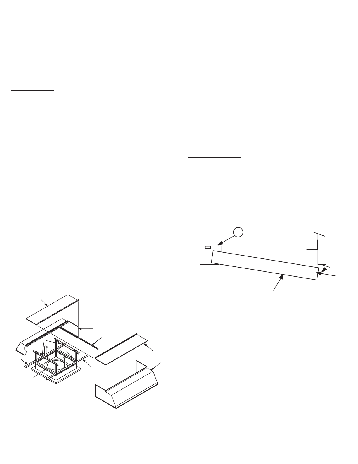
Final Installation Steps
1. Check and tighten fasteners and setscrews, particularly
unit mounting fasteners. Tighten according to the recom-
mended torque shown in the below table, Recommended
Torque for Setscrews/Bolts.
2. Check for correct voltage with voltmeter.
3. Ensure all accessories are installed.
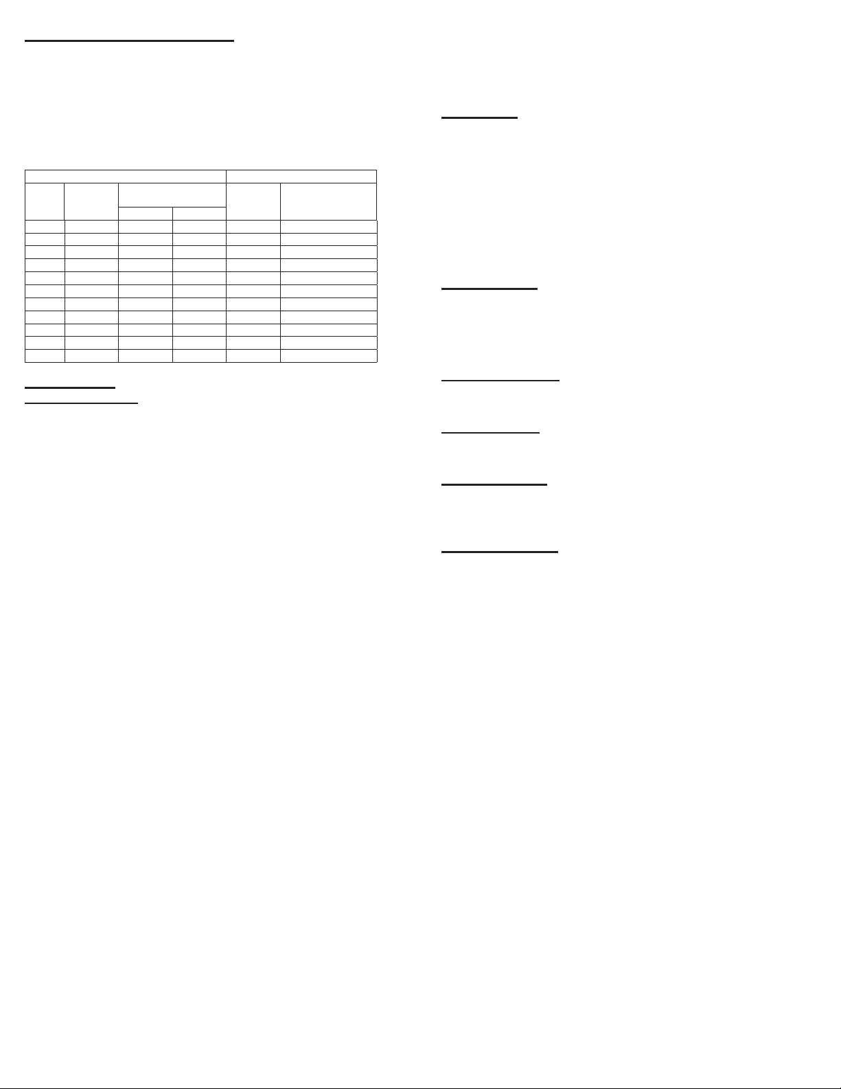
Recommended Torque for Setscrews/Bolts (IN-LB)
Setscrews Hold Down Bolts
Size
Key Hex
Across
Flats
Recommended
Torque Size Recommended
Torque
Min. Max.
#8 5/64” 15 21 3/8”-16 324
#10 3/32” 27 33 1/2”-13 780
1/4 1/8“ 70 80 5/8 ”-11 1440
5/16 5/32” 140 160 3/4”-10 2400
3/8 3/16” 250 290 7/8”-9 1920
7/16 7/32” 355 405 1”-8 2700
1/2 1/4“ 560 640 1-1/8”-7 4200
5/8 5/16” 1120 1280 1-1/4”-7 6000
3/4 3/8” 1680 1920 - -
7/8 1/2” 4200 4800 - -
19/16” 5600 6400 - -
Operation
Pre-Start Checks
1. Lock out all the primary and secondary power sources.
2. Check and tighten fasteners and setscrews, particularly
those used for mounting the unit.
3. Check motor wiring.
4. Rotate the prop to ensure it does not rub against the
venturi.
5. Ensure fan and duct work are clean and free of debris.
6. Close and secure all access doors.
7. Restore power to unit.
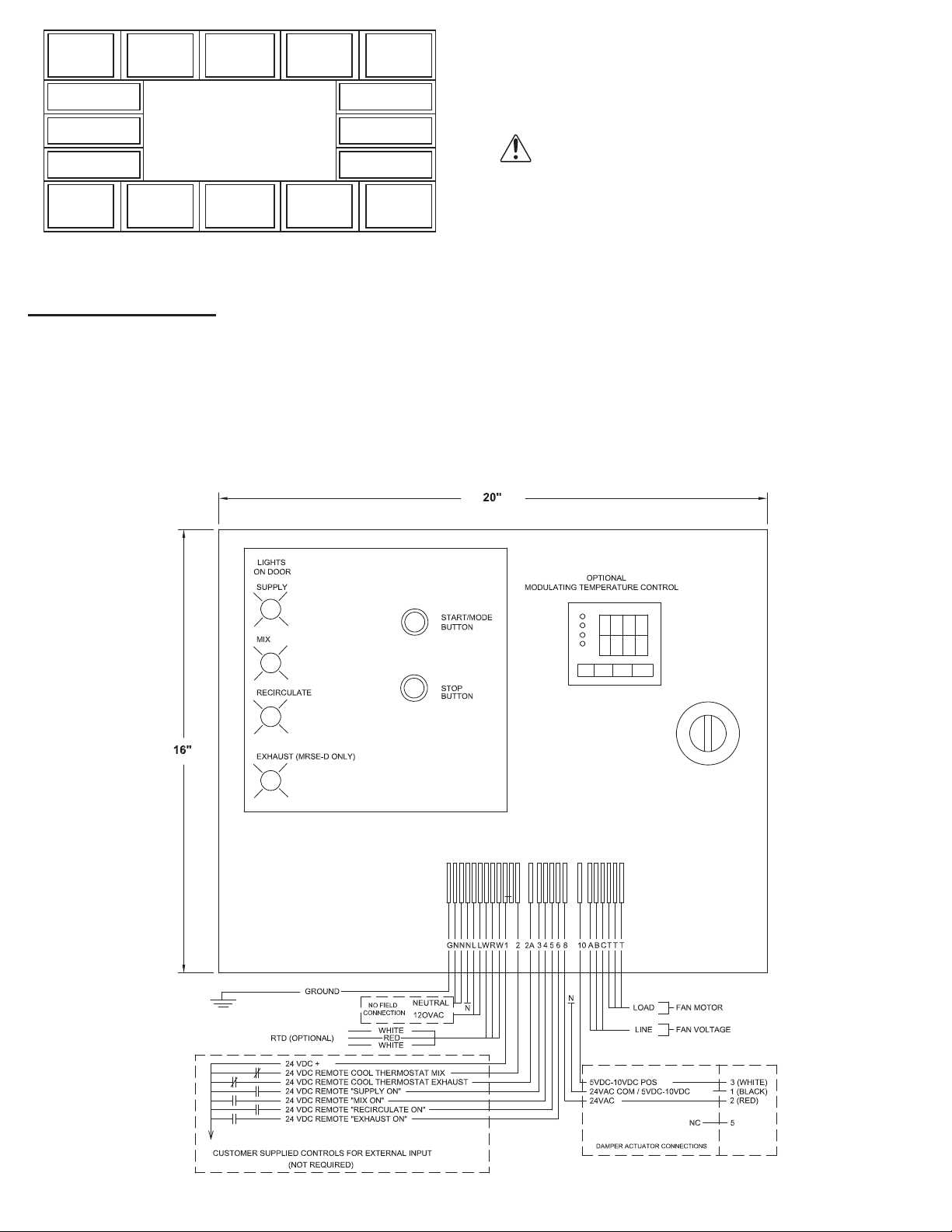
There are four basic designs for the operation control panel
on this unit. They are dened by whether or not the fan unit is
reversible, and whether or not the mix mode is supplied with a
temperature control and modulating dampers.
Modes
MRS-D: mix, recirculate, supply.
MRS-D with Modulating Temperature Controller: mix
dependent upon fan outlet temperature, recirculate, supply.
MRSE-D: mix, recirculate, supply, exhaust.
MRSE-D with Modulating Temperature Controller: mix
dependent upon fan outlet temperature, recirculate, supply,
exhaust.
The function pad on the front of the control panel contains
two operators - a Start/Mode button and a Stop button.
When the Start/Mode button is depressed, the top mode
light will start to flash. This light will flash for three seconds to
indicate that a mode is ready to begin. If the mode button is
pressed again within the three second delay, the next mode
light will begin to flash. If the mode light is allowed to flash for
the full three seconds, the light will then stay on and the fan
will start.
If the panel contains a temperature controller, this module
will be powered only during mix mode. The display on the
temperature controller indicates the outlet temperature of the
fan and the set value which it is trying to produce by mixing
outside air and inside air. The set value temperature must be
between the indoor and outdoor temperatures in order for
the fan to match the set value. Refer to the Control Panel for
programming instructions to set the value temperature.
If the operating mode is changed, such that the direction of
the propeller rotation must change, there will be a 30 second
spin down delay before the start of the new mode.
Start-Up
Turn fan on in supply mode. Inspect for the following:
• Direction of rotation.
• Excessive vibration.
• Unusual noise.
• Improper motor amperage or voltage.
If a problem is discovered, immediately shut the fan o.
Lock out all electrical power and check for the cause of
trouble. Refer to Troubleshooting, page 5.
Inspection
Inspection of the fan should be conducted at the rst 30
minute, 8 hour and 24 hour intervals of satisfactory opera-
tion. During the inspections, stop the fan and inspect as in-
structed.
30 Minute Interval
Inspect bolts, setscrews, and motor mounting bolts. Adjust
and tighten as necessary.
8 Hour Interval
Inspect bolts, setscrews, and motor mounting bolts. Adjust
and tighten as necessary.
24 Hour Interval
Inspect bolts, setscrews, and motor mounting bolts. Adjust
and tighten as necessary.
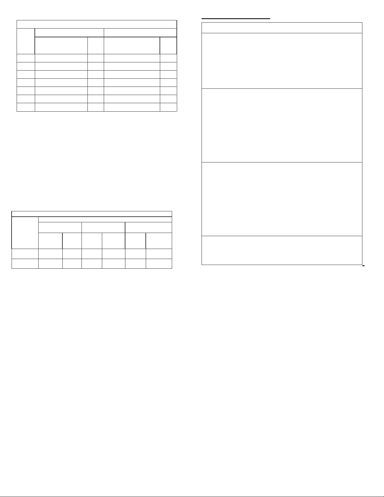
Maintenance
Establish a schedule for inspecting all rotating parts. The
frequency of inspection depends on the operating conditions
and location of the fan.
Inspect fans exhausting corrosive air within the rst month
of operation.
Yearly inspections are recommended for fans exhausting
non-contaminated air.
It is recommended that inspection of the unit be con-ducted
twice annually.
• Inspect bolts and setscrews for tightness. Tighten as
necessary. Refer to Recommended Torque chart
• Inspect for cleanliness. Clean exterior surfaces only.
Removing dust and grease build-up on motor housing
assures proper motor cooling
Clean the propeller and air inlets if material build-up is ex-
cessive. Excessive build-up can cause imbalance and failure
of the propeller. When cleaning the propeller, always clean the
entire propeller. Partial cleaning will cause imbalance and will
lead to unit failure.
Filters
Filters should be checked within the rst two weeks of op-
eration. If there is no excessive build-up, monthly servicing
should be adequate.
To clean reusable aluminum lters, back flush with soap and
water. When clean, shake o excess water and allow the lter
to air-dry before reinstalling it.