Replacing/Installing The Case Fans
1. Replacing / Installing the Rear Case Fan
Step:
1.Remove theside panel
2.Remove fourscrews securing theexterior fan cover.
3.Place therear fan inposition and secureit with fourscrews.
2. Replacing / Installing the Front Case Fans
Step:
1.Remove theside panel
2.Remove thefront panel
3.Remove four screwssecuring the exteriorfan cover
4.Place therear fan inposition and secureit with fourscrews
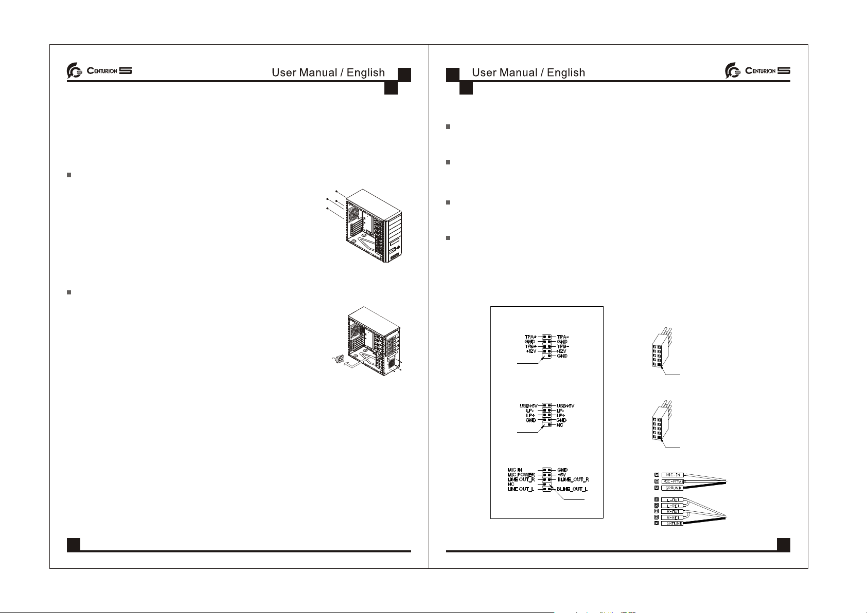
I/O function panel installation guide
Please refer to the illustration on the section of USB,1394,Audio
connector from motherboard user's manual , and please select the
motherboard which use the same USB,1394,Audio standard as
below . Otherwise , it will cause damage for user's device.
The following illustrationis a connectiondiagram for theFront Pane I/Ocable.
Doing so willdamage the device.NEVER connect a1394 cable tothe USB
connector.
NEVER connect aUSB cable tothe 1394 connector. Doing so will damage the
device.
On some motherboardsthe connectors for1394, USB andaudio are notthe
same as thebelow drawing. Pleasecheck with yourmotherboard manual
before install.
IEEE 1394 Connector
USB Connector
Front panel audioconnector (BLACK)
Front panel USBconnector
No Pin
Front panel audioconnector
No Pin
Pin
Front panel IEEE1394 connector
Mother Board
No Pin
Cable
Pin
06 07
Replacing/Installing The Case Fans
1. Replacing / Installing the Rear Case Fan
Step:
1.Remove theside panel
2.Remove fourscrews securing theexterior fan cover.
3.Place therear fan inposition and secureit with fourscrews.
2. Replacing / Installing the Front Case Fans
Step:
1.Remove theside panel
2.Remove thefront panel
3.Remove four screwssecuring the exteriorfan cover
4.Place therear fan inposition and secureit with fourscrews
I/O function panel installation guide
Please refer to the illustration on the section of USB,1394,Audio
connector from motherboard user's manual , and please select the
motherboard which use the same USB,1394,Audio standard as
below . Otherwise , it will cause damage for user's device.
The following illustrationis a connectiondiagram for theFront Pane I/Ocable.
Doing so willdamage the device.NEVER connect a1394 cable tothe USB
connector.
NEVER connect aUSB cable tothe 1394 connector. Doing so will damage the
device.
On some motherboardsthe connectors for1394, USB andaudio are notthe
same as thebelow drawing. Pleasecheck with yourmotherboard manual
before install.
IEEE 1394 Connector
USB Connector
Front panel audioconnector (BLACK)
Front panel USBconnector
No Pin
Front panel audioconnector
No Pin
Pin
Front panel IEEE1394 connector
Mother Board
No Pin
Cable
Pin
06 07


 user manual")