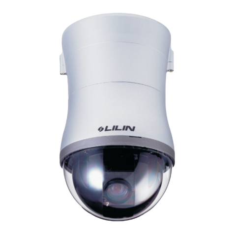
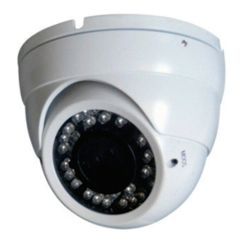
COP Security 15-CD521W User manual

Installation and Operation Manual
for
Speed DomeCamera
15-CD521W/15-CD523W
Pleaseread the operation manualcarefully
before installing and using thisunit
VER:1.1

SPECIFICATION
ITEMS 15-CD521W 15-CD523W
ZoomCamera CZ40HCM CZ55HCM
SYNC System InternalMode/External(AC Lock)Mode( 1Hz)
Scanning System 1:2 Interlace
PickUpDevice 1/4“Sony SuperHAD CCD
EffectivePixels 768 (H)X494 (V)(NTSC)752 (H)X582 (V)(PAL)
S/N Morethan46 dB
( = 1 AGCOFF APCOFF Y-out)
HorizontalResolution
480 TVLines
Lens F1.6(W) ~1.9(T)/
f=3.7(W)~37.8(T)mm F1.6,=3.8(W)~87.4(T)
Zoom 10XOpticalZoomand10X
DigitalZoom
(TheTotalZoomRatio 100X)
23XOpticalZoomand10X
DigitalZoom
(TheTotalZoomRatio 230X)
WhiteBalance ATW/AWB/FIX(Zero ColorRolling)
ALC Auto/Fix(OSDControl)
AGC Auto GainControl(+24dBMax)
BLCFunction SuperBLC, 48 ZoneBLC
Illumination 0.03 Lux(ICR ON/F1.8/5600°K/50IRE)
ElectronicShutter AES:1/60(1/50) ~1/120,000 sec. Manual:8 Step
GAMMACorrection 0.45 /1
Video SignalOutput 1.0Vp-p/75Ω
ExternalControl RS485
Pan PanRange360°/Speed0.5 ~240°/s
Tilt TiltRange90°/Speed0.5 ~120°/s
Preset 128 PresetPositions(Max)
Auto Cruise 1Auto CruisingTracks(Max)
Operation
Temperature -10℃~50℃
OperationHumidity Within85%RH
PowerSource DC12V 0.5V, 3.6W(Max)

CONTENTS
1. PRECAUTIONS-------------------------------------------------------- 2
2. OPERATION------------------------------------------------------------ 4
3. IDSETTING------------------------------------------------------------- 8
4. PROTOCOLSETTING----------------------------------------------- 10
5. CONSTRUCTION----------------------------------------------------- 10
5.2OUTDOORSPEEDDOMECAMERA-----------------------------------------11
6.TROUBLESHOTING------------------------------------------------- 12
7. CONNECTIONOFRS485 BUSAND
TERMINATIONRESISTER----------------------------------------- 13
8. INSTALLATION-------------------------------------------------------- 15
8.1INDOORSPEEDDOMECAMERA--------------------------------------------15
8.2OUTDOORSPEEDDOMECAMERA-----------------------------------------15
APPENDIX : MENU OFCOPZOOMMODULE------------------- 20

VA
W
)
Relation TableofDC12VCableDiameterand Transmission distance
When thecablediametersequal,andvoltagewastagerateofDC12Visunder10%,themaximum
transmissiondistanceisrecommended.(AstoACequipments,themaximumallowedvoltage
wastagerateis10%)Forexample:Anequipmentwithrating powerof80VA andinstalledat10
metersawayfromtransformerdemandsthemaximumcablediameterof 0.8mm (squaremeter).
CableDiameter(mm)SquareMeter
F
eet(m)
0.8000 1.000 1.250 2.000
10 283 86)451 137)716 218)1811 511)
20 141 42)225 68)358 109)905 275)
30 94 28)150 45)238 109)905 275)
40 70 21)112 34)179 54)452 137)
50 56 17)90 27)143 43)362 110)
60 47 14)75 22)119 36)301 91)
70 40 12)64 19)102 31)258 78)
80 35 10)56 17)89 27)226 68)
90 31 9)50 15)79 24)201 61)
100 28 8)45 13)71 21)181 55)
110 25 7)41 12)65 19)164 49)
120 23 7)37 11)59 17)150 45)
130 21 6)34 10)55 16)139 42)
140 20 6)32 9)51 15)129 39)
150 18 5)30 9)47 14)120 36)
160 17 5)28 8)44 13)113 34)
170 16 4)26 7)42 12)106 32)
180 15 4)25 7)39 11)100 30)
190 14 4)23 7)37 11)95 28)
200 14 4)22 6)35 10)90 27)
●Lightning proofequipmentmustbeinstalledwhenthespeed
domecameraisinstalledinopenarea.
●Makesuretheinputvoltageand normalratedpowerbefore
poweredup.
Warnings

2
1. PRECAUTIONS
(1)Donotattempttodisassemblethecamera.
Toprevent electricshock, do not removescrewsorcovers.
Thereareno user-serviceablepartsinside.
Ask qualifiedservicepersonnelforservicing.
(2)Handlethecamerawithcare.
Donotabusethecamera.Avoidstriking,shaking,etc.Thecameracouldbedamagedbyimproper
handling orstorage.
(3)Donotuse strong orabrasive detergentswhencleaning thecamerabody.
Useadryclothtoclean thecamerawhenit isdirty.
Whenthedirtishardtoremove,useamilddetergentand wipegently.Careshouldbetakennotto
scratchthedomewhenwiping it.
Afterwards, wipeoff theremainedpart of thedetergent init withadrycloth.
(4)Neverface thecameratowardsthesun.
Donot aimthecameraat bright objects.Whetherthecameraisinuseornot,neveraimitat thesun
orotherextremelybright objects. Otherwise, blooming orsmearmaybecaused.
(5)Neverface thecameratowardsaplace exposedtolightsources foralong time.
If lightsourcessuchasspotlightcauseburn-inon thedisplayscreen,partofimagemaydiscolor
duetodeterioration of colorfilterinCCD whenchanging aimof thecameraetc.
(6)Donotinstall thiscameraupsidedown.
Thiscameraisdesignedformountingontheceiling orwall. Usingthiscamerainstalledupsidedown,
forexample, mountedon thefloor, maycausemalfunction.
(7)Donotoperatethecamerabeyond thespecifiedtemperature,humidityorpowersource
ratings.
Donotusethecamerainan extremeenvironmentwherehigh temperatureorhighhumidityexists.
Donot placenearheat sourcessuchasradiators, stovesorotherunitsthat produceheat.
UsetheIndoorSpeedDomecameraunderconditionswheretemperatureisbetween-10 C-+40 C,
and humidityisbelow90 %. Theinput powersourceisDC12V.
(8)Donotinstall thecameraneartheairout-letofanairconditioner.
Thelensmaybecomecloudyduetocondensationifthecameraisusedunderthefollowing
conditions.
•Rapidtemperaturefluctuationsbyswitching theairconditioneron and off
3
•Rapidtemperaturefluctuationsduetofrequent dooropening and closing
•Useinan environment whereeyeglassesbecomefoggy
•Useinaroomfilledwithcigarettesmokeordust.
Ifthelensbecomes cloudyduetocondensation,removethedomecoverandwipeallmoist
surfaces withasoft cloth.
(9)Consumables
Partshavingcontactssuchasthelens-drivemotors,cooling fan motorandslip-ringsbuiltinsidethe
cameraaresubjecttowearwithtime.Aboutreplacementandmaintenanceofsuchparts,pleaseask
thenearest servicecenter.
(10)Donotaimthecameraatthesameobjectforalong time.
Burn-inof an imagemaybecausedon thefluorescent screenof CRT.
2.OPERATION
Thespeeddomecameracan becontrolledremotelyhorizontaland verticalmovement.Itis
controlled remotelyfromthekeyboardorcontrollerthrough aserialconnectiontotheRS-485
connector.
Thespeeddomecamerawillconductaself-check afterpoweredup and themonitorwill
displayas following:P:P_D ID:001 V:2。A2M”.Theinformationwill bedisappearedafter
theself-check isfinished.(Protocoland IDcodewillbedisplayedaccordingtotheusers’
choice)
Ifthereisanyalteration, please according toactual productedition.
Normal Function:
2.1Pan/TiltFunction
Thecameraiscapableofmoving verticallyandhorizontally.ThePan/Tiltspeedisvariableforgiven
amount of joystick deflection.
2.2LensFunction
2.2.1ZoomLensFunction
Transformtheviewangleof thecamera zoomin/ zoomout), press[TELE] or[WIDE]。
2.2.2FocusFunction
Insomespecialcircumstance,usersneedconductfocusmanual,hecanpress[NEAR]or[FAR]to
transformthefocusandpress[CALL]+59+[ENTER]oroperatethejoysticktorecovertheauto
mode.
2.2.3IrisFunction
Innormalcircumstance,irisisinautomode.Ifusersneedtochangetheirislevel,theycanpress
[OPEN] or[CLOSE] toadjust. Press [CALL] +60 +[ENTER] oroperatethejoystick,iriswill beauto.

4
2.3PresetFunction
Thespeeddomecameraiscapableofgoingto128presetpositions.EachiswithitsownP/T/Zand
focus. Preset positions50-66arereservedforauxiliaryfunctions.)Whenpreset acameraposition,
theP/T/Zand focuswill bememorizedforthat position.
2.3.1Tosetapresetposition
[PRESET] +nnn +[ENTER], theMonitor displays:SETPRESET :nnn
nnn→thenumberof preset position: 1~128
2.3.2Tocall apresetposition
Whencamerapositionshavebeenpreset, you can enteramemorizedcameraposition number.
[CALL] +nnn +[ENTER], the Monitordisplays:CALLPRESET:nnn
nnn→thenumberof preset position: 1~128
2.3.3Todeleteapresetposition:OnlybeeffectivetoProtocolCOP-2. Somespecialkeyboards
no function)
[DELPRESET] +nnn +[ENTER], theMonitordisplays:CLEARPRESET :nnn
nnn→thenumberof preset position whichwill bedeleted
2.4AuxiliaryFunctionsList
Operation Function
F1 +0 +Off Camerareset
F1 +1 +On Backlightcompensation ON
F1 +1 +Off Backlightcompensation OFF
F1 +2 +On LOWillumination ON
F1 +2 +Off AutoLOWillumination
F1 +3 +On Menu/DisplayON
F1 +3 +Off Menu/DisplayOFF
F1 +4 +On DigitalzoomON
F1 +4 +Off DigitalzoomOFF
F1 +5 +On KeyboardLCDdisplay BackLight ON
F1 +5 +Off KeyboardLCDdisplay BackLight OFF
F1 +6 +On AutoFOCUS
F1 +6+Off ManualFOCUS
F1 +7 +On AutoIRIS
F1 +7+Off ManualIRIS
F1 +8 +On Auto Whitebalance (AWB)
F1 +10 +On Whitebalance Autofollowmodel (ATW)
F1 +11 +On Colorpicture
F1 +11+Off B/Wpicture

5
Operation Function
Call +33 +Enter Pan180°
Call +51+Enter Scanstart
Preset+51+Enter Setthestartposition ofscan
Call +52+Enter Scanstop
Preset+52+Enter Settheend position ofscan
Call +53 +Enter AutocruisefromNo.1 presetposition toNO.16 presetposition
Preset+53+Enter Doself-test
Preset+54+Enter Camerareset
Call +55+Enter Backlightcompensation ON
Preset+55+Enter Backlightcompensation OFF
Call +58+Enter DigitalzoomON
Preset+58+Enter DigitalzoomOFF
Call +59+Enter AutoFOCUS
Preset+59+Enter ManualFOCUS
Call +60+Enter AutoIRIS
Preset+60+Enter ManualIRIS
Call +61+Enter Auto Whitebalance
Preset+61+Enter ManualWhitebalance
Call +63+Enter ImageMirrorON
Preset+63+Enter ImageMirrorOFF
Call +64+Enter Showofoperation (title)
Preset+64+Enter Noshowofoperation (title)
Call +67+Enter Colorvideo
Preset+67+Enter B/Wvideo
Call +90+Enter Running SEQafterfiveminutesOFF
Preset+90+Enter Running SEQafterfiveminutesON
Call +95+Enter Cameramenu ON
Preset+95+Enter Cameramenu ON

6
Operation Function
Call +n+Enter Tocall thenumberNpresetposition
Preset+n+Enter TosetthenumberNpresetposition
Preset+n+Off DeletethenumberNpresetposition
Cam+n+Enter Setthedomeaddress n”
Shot+1+Enter Autothecruisetrack
Shot+1+Off Stop thecruisetracks
Auto+On Setthestartposition ofautopan
Auto+Off Settheend position ofautopan
Auto+Enter Thecamerawillmovefromtheautopanstartpositiontothe
autopanend position
Wide ZOOMwide
Tele ZOOMtele
Far FOCUSfar
Near FOCUSnear
Open IRISopen
Close IRISclose
(1)TitleDisplayFunction
No.64presetpositioncanturnonorturnoff thedisplayfunction(including self-checkinformation
display)ofsomecertaincameras.IftheNo.64presetpositionisanormalone,thecameradoesnot
havethedisplayfunction (including self-check information display).
(2)Whencameraperformscruise function, thetolerantstateisas follows:
ToscanpointbypointautomaticallyfromNo.1presetposition toNo.16presetposition.Thecruise
willnot scanthosepositionswherecertainpositionsareun-presetordeletedafterpreset, and resort
timeforeachpreset position is3seconds;
(3)Whencameraperformsscanfunction, thetolerantstateisas follows:
Thecamerawillscanautomaticallybetweentwodesignatedpositions,namely “startingpoint”(left)
and “end point”(right).Theresorttimeat “startingpoint”and “endpoint”is3seconds;statesof
domecameraareshownbelow.Thedomecamerawill stopscanandimplementnewaction
whenreceiving qualifiedcommand.
Note: Thedomecameramayresultinaccumulativedeviation inparametersafterservingalong
period.Thestarting point and end point of scan shall bereset.
(4)Theitemmarkedwith*meansthecamerahavethisfunction,otherwise itwillshow NO
FUNCTION”。

7
5. Special Function—Power-off Protection
When thecameraisunderscanorcruisetrack,and poweroffoccurs,thecamerawillsavethestate
beforethepower-off.Whenpowerisresupplied,thecamerawillcontinuetoperformthescanor
cruisetrackautomaticallyunderthesamestatebeforepower-off. Shouldscanorcruisetrackarenot
performedbeforepower-off, thecamerawill stop at thefirst preset position automatically.
3.IDSETTING
IDofthisspeeddomecanbesetbytheswitchwith10codes. Belowisthe detail ofsettingID
code:

8
ˉˉˉˉˉˉˉˉˉˉˉˉ
Note:Controlcablescan connectmultiplespeeddomecamerasinparallelprovidedthatNo.10 ID
codeofthefarthestcameraissetto “ON”.Theoperationisrequiredwhenthecontroldistanceis
quitefar.
TheNo. 10 IDcodeshouldbeset to “ON”forthelast cameraconnectedtothedaisy
chain.
4.PROTOCOLSETTING
Protocolofthisspeeddomecan beset bytheswitchwith3protocolcodes. Belowisthe detail of
settingprotocolcode:
Note:All setting mustbeoperatedafterpoweroff.
Poweron until itiscompleted.!
Protocolsetting

9
5.CONSTRUCTION
◆CONNECTIONS
PRECAUTIONS
※Thefollowing connectionsshouldbemadebyqualifiedservicepersonnelorsystem
installersinaccordance withall local codes.
Note: Whenpoweredup,thecameraperformsaself-check forabout2minutes(includingone
panning,tilting,zoomingandfocusingoperation).Duringtheperiod,controloperationsarenot
executed.
1Wall Mount
2DC12VInput
3VideoOutput
4RS485 data
5Camera
6Acylicdome
7AluminumDieCast Housing
1
23
4
5
6
7
VideoOutput
RS485Signal
OrangeRS485+
YellowRS485-
+
-
DC12V

10
6. TROUBLESHOTING
Trouble PossibleCauses Solution
Powersupplyisnot well connected Replace
Engineering cablefailure Eliminate
Noaction,novideo after
poweredup Thepowersupplyisnot well connected Correct
Machinefailure Repair
Thecameraisdeclining Put straight
Self-checkisn’tnormal,but
imageisnormalandobstacle
found inoperation. Voltageislow
Changepowerand placeit nearthe
camera
Thedistancebetween DC12V power
supplytodomecameramust beless
50 meters
Thecontact ofvideo cablesisincorrect Correct
Thecontact ofvideo cablesisloose Eliminate
Self-checkisnormalbutno
image Cameraisdamaged Replace
TheconnectionofcontrolsignalisincorrectCorrect
Cameranumberisnot set correctly.Reinstall
Protocolsetting isincorrect Correct
RS485 cableA+&B-connectionisnot correct Correct
RS485 cableistoo long ThemaximumcableforRS485
communicationis1.2km
Self-checkisnormalbutitis
uncontrollable
RS485 signalnetworkisstarconfiguration Stardistributorisusedat junctionof
connection
Thecontact ofvideo cablesisloose Eliminate
Instableimage Voltageislow Replace
Dropout occursduetolowvoltage CheckIDaddress settings
Self-checkisabnormal Powerup again
Theoperationofmainframeisnot correct Powerup again
Thecameraisuncontrollable
and running unceasingly RS485 buslineisn’t equippedwithmatched
resistance, ortheresistanceisnot matched. Correct
Abnormalvideo Extremelybright video Noterminationorhigh resistance
7. CONNECTIONOFRS485 BUSAND TERMINATIONRESISTOR
(1)Characteristics ofRS485 Bus
AsspecifiedbyRS485standards.RS485Busisofhalfduplexeddatatransmissioncables
withcharacteristicimpedance as12.Themaximumloadis32 unitloads(including main
controllerand controlledequipment.)
(2)TheRS485standardarequireadaisy-chainconnectionbetweentheequipment. Theremust
betermination resistorwith120 ohmsimpedanceatbothendsoftheconnection (refertothe
following FIGURE)
WhenNo. 10 bitoftheDipissetto ON”, the120 ohmstermination resistorisconnected.

11
(3)ProbleminPractical Connection
Insomecircumstancesuseradoptsastarconfiguration inpracticalconnection.Thetermination
resistorsmustbeconnectedtothetwoequipments(No.6andNo.10)thatarefarthestaway
fromeachother. Buttheconnection does notmeettheRS485 standards.
Whenthecabledistanceofequipmentsarefaraway,someproblems,suchas signal
reflection,anti-jammingabilitydecreaseareeasilyoccurand resultinthereliabilitydeclineof
controlsignal.Theresultedphenomenarepresentthatthecameraisoutofcontrol
completelyorinterruptedlyoroperatesautomaticallyand failstostop,etc.Insuch
circumstancesthefactoryrecommendstheRS485SignalDistributor.Thedistributorcan
changethestarconfigurationconnection tothemodeofconnectionstipulatedintheRS485
standards. Themewconnection achieves reliabledatatransmission.
RS485 Distributor
Eachconnection can connect 32 terminations, and practicalconnectionsmust beconsidered.
Control
120Ω
120Ω
120Ω
1#
6#
12#

12
ProtocolandID
ProtocolandID
8. INSTALLATION
8.1OUTDOORWALLMOUNT
①TaketheAcylicdomeapartfirstly,choosetheIDcodeand protocolcodesecondly,mountthe
Acylicdomeagainfinally. (fig.1)
②Putthewireintothewallmountbracket,thensecurethe domecameraand bracketbyscrews.
(fig.2)
③Connect all thecablesasrequired..
④Mount thedomecamerafirmlyon thewall byscrews. (fig3)
8.2INDOOR CEILING MOUNT(Option)
①TaketheAcylicdomeapartfirstly,choosetheIDcodeand protocolcodesecondly,mountthe
Acylicdomeagainfinally. (fig.1)
②Putthewireintotheceiling mount bracket, thensecurethedomecameraand bracket byscrews.
(fig.2)
③Connect all thecablesasrequired..
④Mount thedomecamerafirmlyon thewall byscrews. (fig3)
Fig1.
Fig1.
Fig2.
Disassemble
Mount
Fig2.
Disassemble
Mount
Fig3.
Fig3.

13
APPENDIX :MENU OF COPZOOMMODULE
How toenterthemenu ofCOPzoommodule
1.Toexecutethe order CALL+95+ENTERintothe menu.
2. Then you will see the menu of COPmodule
MainMenu (Page1. )
S
E
T
U
P
M
E
N
U
(
1
/
3
)
è
W
H
I
T
E
B
A
L
A
N
C
E
I
R
I
S
A
G
C
S
E
N
S
B
A
C
K
L
I
G
H
T
E
N
H
A
N
C
E
R
Z
O
O
M
F
O
C
U
S
H
/
V
R
E
V
E
R
S
E
T
I
T
L
E
P
R
E
S
E
T
MainMenu (Page2. )
S
E
T
U
P
M
E
N
U
(
2
/
3
)
è
M
O
T
I
O
N
D
E
T
E
C
T
P
O
S
I
T
I
O
N
G
A
M
M
A
P
O
W
E
R
O
N
M
A
S
K
O
S
D
Z
O
O
M
+
A
F
L
A
N
G
U
A
G
E
C
O
M
M
I
D
MainMenu (Page3. )
S
E
T
U P
M
E
N
U
( 3
/ 3
)
è
C
R
O
S
S
L
I N
E
F
R
E
E
Z
E
P
O
S
I / N
E
G
A

14
Sub Menu
White Balance
W
H
I
T
E
B
A
L
A
N
C
E
è
C
O
L
O
R
O
F
F
O
N
è
A
U
T
O
W
B
è
A
T
W
R
-
-
-
■
-
-
B
A
W
B
R
-
-
-
■
-
-
B
G
A
I
N
è
R
-
Y
-
-
-
-
■
-
-
-
B
-
Y
-
-
-
-
■
-
-
-
This is usedtocontrolthecolorON/OFF andwhite
balance andthegainrateofRED&BLUEcolor.
1. 「COLOR」selector:OFF is monochromeimage,
ON is normalcolorimage,AUTOis atlowlightAGC
up, displayimagewill beautochangetomonochrome
image.
2. 「WB」Whitebalance control:ATWisAutotrace
whitebalance,canbeadjustoffsetlevel.AWBis One
pushwhitebalance. Push[menu]key「AWB」will start
flicker, until flickerstop itwill lockthecurrentcolor
temperatureatthesametime.
3. 「GAIN」: ThegainrateofR-Y&B-Ycanbe
adjustedseparately.

15
IRIS
I
R
I
S
è
P
E
A
K
è
O
F
F
O
N
A
■
-
-
-
-
-
P
A
L
C
è
A
U
T
O
-
-
-
■
-
-
-
F
I
X
-
-
-
■
-
-
-
A
E
S
A
U
T
O
-
-
-
■
-
-
-
è
F
I
X
O
F
F
Thisis usedtocontroltheiris &shutterspeedofthelens.
Itincluded3items PEAK”, ALC”, AES”.
1. PEAK」is usedtocontrolthereactionofautoiris,
whichis based ontheaveragelightofpicturesignalor
thelightrateofthepeak.
2. ALC」is usedtoselectAUTOorFIX.AdjustIRIS
level.
3.
AES」
isusedtoselectelectronicshutterbeAUTOor
FIXfunction, atAUTOmodecanbeadjustAES
level,atFIXmodecanbeselectorshutterspeedatbelow,
[OFF]
,
[1/100sec]
,
[1/120sec]
,
[1/250sec]
,
[1/500sec],
[1/1000sec],[1/2000sec],[1/4000sec],[1/10000sec]
AGC SENS
A
G
C
▪
S
E
N
S
A
G
C
A
U
T
O
-
-
-
-
-
-
■
S
E
N
S
A
U
T
O
■
-
-
-
-
-
-
This is usedtoselect「AGC」and「SENS」function.
1.「AGC」: Toadjustautogaincontrol, 0dBb~24dB9
steps adjustable.
2. 「SENS」: Forlowlightapplication:0Frame,6
Frame,12 Frame,16Frame,18 Frame,22 Frame,
24 Frame,30 Frame,36 Frame, 9steps adjustable.

16
BACKLIGHT
B
A
C
K
L
I
G
H
T
è
O
F
F
O
N
è
A
R
E
A
S
E
N
S
L
O
W
-
-
-
-
■
-
-
-
H
I
This is usedtocontrol BLC”(BackLight
Compensation),
1. BLC」ON /OFF selector. Selector「ON」has 2
sub-items:「 AREA」,「 SENS」.
2.「AREA」:48 BLCzones canbesetseparatly.
According tothemaskarea (BLCzone)signaltodecide
theiris andshutterspeed.
3.「SENS」: Is usedtoenhance theBLCeffect.
ENHANCER
E
N
H
A
N
C
E
R
H
▪
G
A
I
N
-
-
-
-
-
-
■
-
-
-
V
▪
G
A
I
N
-
-
-
-
-
-
■
-
-
-
This is usedtoenhance thecompensationofthepicture
quality.
1.「H •GAIN」: HorizontalCompensation
2.「V •GAIN」: VerticalCompensation

17
ZOOM FOCUS
Z
O
O
M
▪
F
O
C
U
S
è
D
I
G
I
T
A
L
Z
O
O
M
O
F
F
Z
O
O
M
S
P
E
E
D
-
-
-
■
-
-
F
O
C
U
S
S
P
E
E
D
-
-
-
■
-
-
Z
O
O
M
W
I
D
E
T
E
L
E
F
O
C
U
S
è
M
A
N
U
A
L
I
N
F
N
E
A
R
A
U
T
O
This is usedtocontrolthemontionofthelens, included
DigitalZOOM”ON/OFF andtimes setfunction.
1. DigitalZOOM」selector:OFF、X2、X4、X6、
X8、X10.
2.「ZOOM Speed」: Setthespeedofthezoom.
3.「FOCUSSpeed」: Setthespeedoffocus.
4.「ZOOM」: Lens ZOOM adjustWIDE/TELE
5.「FOCUS」: AUTO/MANUALsetting
H/VREVERSE
H
/
V
R
E
V
E
R
S
E
è
H
▪
R
E
V
E
R
S
E
è
O
F
F
O
N
V
▪
R
E
V
E
R
S
E
è
O
F
F
O
N
This is usedtoselectimage「HorizontalReverse」and
「VerticalReverse」function.
This manual suits for next models
1
Table of contents