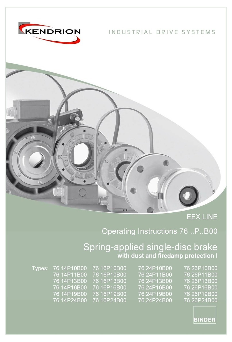
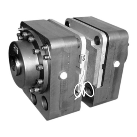
COREMO OCMEA ID 3000 Operating instructions

HYDRAULIC BRAKE
ID 3000
COREMO OCMEA S.P.A.
Via Galilei, 12 - 20090 Assago (MI) - Italy
Tel. +39 024880697 Fax +39 024881940
User and Maintenance Manual
Translation of the original instructions
EN 140701 REV. 1.0
ISO 9001 - Certificate N°0238

User and Maintenance Manual
Hydraulic brake ID 3000
Model ID 3000
Date: 2014/07/01
Revision: 1.0
www.coremo.it
Pag. 2di 13
TABLE OF CONTENTS
1. Introduction ............................................................................................................................................ 3
2. Manufacturer .......................................................................................................................................... 3
3. General information................................................................................................................................ 3
4. Warnings ................................................................................................................................................. 5
5. Technical data ......................................................................................................................................... 6
5.1. Product performance .............................................................................................................................. 6
5.2. Brake lining wear..................................................................................................................................... 6
5.3. Special note............................................................................................................................................. 6
6. Transport and storage............................................................................................................................. 7
7. Installation............................................................................................................................................... 7
8. Operation ................................................................................................................................................ 9
8.1. Power supply of the safety component .................................................................................................. 9
8.2. Improper use........................................................................................................................................... 9
9. Maintenance and cleaning.................................................................................................................... 10
9.1. Changing the linings pads...................................................................................................................... 10
9.2. Cleaning the friction surfaces................................................................................................................ 10
9.3. Changing the sealing rings..................................................................................................................... 11
9.4. Changing the springs ............................................................................................................................. 11
9.5. Periodic maintenance............................................................................................................................ 12
10. Spare parts list....................................................................................................................................... 13

User and Maintenance Manual
Hydraulic brake ID 3000
Model ID 3000
Date: 2014/07/01
Revision: 1.0
www.coremo.it
Pag. 3di 13
1. Introduction
The purpose of this manual is to provide the user with all the information necessary to use the
product properly, independently and safely.
This manual constitutes an integral part of the safety features and must be read in its entirety
before installation and use of the product. It must therefore be kept in a safe place should future
reference be necessary before proceeding with any kind of work.
The user is strongly advised to read it carefully and to follow the rules and procedures contained
in it as these provide important information concerning safe use and maintenance.
If any doubt should arise concerning the correct interpretation of the instructions, contact our
technical department for the necessary clarification.
It is prohibited for anyone to disclose or modify the content of this manual or to use it for
personal purposes.
2. Manufacturer
COREMO OCMEA S.P.A.
Via Galilei, 12 - 20090 Assago (MI) - Italy
Tel.: +39 024880697 Fax: +39 024881940
3. General information
Correct use of the product: In compliance with Italian Legislative Decree 17/2010 and DIRECTIVE
2006/42/EC the operating limits for perfect and safe use of the product are stated in this manual.
Design parameters: COREMO OCMEA brakes have been designed in compliance with the norm UNI EN
ISO 12100:2010 and to satisfy the performance requirements and conditions stated in the catalogue and
in Chapter 5 of this manual.
Model selection: Selection of the correct model for a given application is of basic importance. The
technical department of COREMO OCMEA can provide you with information, suggestions and assistance
regarding correct application and use.

User and Maintenance Manual
Hydraulic brake ID 3000
Model ID 3000
Date: 2014/07/01
Revision: 1.0
www.coremo.it
Pag. 4di 13
Use: Following the mounting and maintenance instructions prevents costly down time and accidents
due to incomplete knowledge of the product. Please note that the initial torque may be from 30% to
50% less than the rated value until the brake lining adjusts to the disc.
Rotating parts: The brakes are coupled mainly with rotating parts. In this case the moving parts must be
protected in conformity with the requirements of DIRECTIVE 2006/42/EC and Italian Legislative Decree
17/2010 or equivalent legislation in force in the countries in which they are used.
Power source for hydraulic brakes: Use mineral oil SAE/ISO 46.
Friction material: All COREMO OCMEA brakes are fitted with friction material which is absolutely free of
asbestos and is declared as NON toxic/harmful in full observance of health and environment regulations
and laws. In any case it is better not to inhale dust produced by them and to wash hands thoroughly
before eating or drinking.
Oils, greases, lubricating components: These are used in extremely limited quantities. Personnel
suffering from allergies to these substances are advised to wear gloves or use protective cream which
must be washed off thoroughly before eating or drinking.
Cleaning of the product: Do not wash the product with water or any detergent.
Product markings: All the data on the plates must always be kept legible. Use the data shown on the
plates when contacting the manufacturer for spare parts, information or assistance for example.
Disposal: Worn brake linings and other materials of which brakes are made are classified as special NON
toxic/harmful products and therefore must be disposed of in accordance with the laws in force in the
countries in which they are used..

User and Maintenance Manual
Hydraulic brake ID 3000
Model ID 3000
Date: 2014/07/01
Revision: 1.0
www.coremo.it
Pag. 5di 13
4. Warnings
Failure to follow the instructions in this manual and on any plates attached to the
product exposes persons to risks and may cause damage to other equipment and
machinery.
˗The product must not be used at an ambient temperature lower than -20 °C.
˗The disc must be made of iron alloy (cast iron or steel) having a hardness in the range 190 to 220
HB.
The technical department of COREMO OCMEA can provide additional information in order to ensure
correct application and use of the product.
Dangers caused by a power failure: A power failure will stop the brake from working. It is therefore
necessary to provide an uninterrupted power supply or, if the case requires, use suitable power failure
warning systems as a brake failure may cause personal injury and damage to property.
Danger of breakage during operation: To reduce the risk of breakage during operation carry out the
periodic inspections shown in this manual.
Risks connected with changes in operating conditions: The product is designed for the purposes stated
in this user and maintenance manual therefore the brake power supply pressure is indicated to ensure
that braking is always safe and reliable. The operating conditions also vary depending on the diameter of
the brake disc used; an equation for calculating the dynamic torque as a function of disc diameter is
given in this manual. It should be stressed that an error in calculation will result in a braking torque that
is different from the desired value and this may represent a risk to safety.
Residual risk: Residual risk can be attributed to the operator not following all the procedures stated in
the user and maintenance manual and not giving due consideration to the warnings.

User and Maintenance Manual
Hydraulic brake ID 3000
Model ID 3000
Date: 2014/07/01
Revision: 1.0
www.coremo.it
Pag. 6di 13
5. Technical data
5.1. Product performance
The brake is to be used exclusively for service stops.
Use of the product for any purpose other than those indicated may represent a risk to
any aspect of safety.
The ID 3000 brake applies a tangential force of 300 kN when powered at a pressure of 100 bar and
attributing a coefficient of friction of 0.4
Warning: The value of the friction coefficient is purely theoretical as it depends on environmental
conditions and on how the product is used.
Dynamic torque
The dynamic torque provided by the brake will be a function of the diameter of the disc used and can be
determined using the following equation:
Dynamic torque [Nm] = Tangential force [N] x ( radius of the disc [m] - 0.124 )
An error in calculation will result in a braking torque different to the desired value and a
risk to aspects of safety.
The technical department of COREMO OCMEA can provide information, suggestions and
assistance for correct application and use of the product.
5.2. Brake lining wear
The thickness of each single new lining is 16 mm. A maximum overall lining wear of 20
mm is allowed. Failure to remain within the above limit may represent a risk to aspects
of safety.
5.3. Special note
During braking kinetic energy is converted into heat caused by friction between the surfaces of
the brake linings and the brake disc. It is therefore fundamentally important to consider the
amount of heat that can be dissipated.

User and Maintenance Manual
Hydraulic brake ID 3000
Model ID 3000
Date: 2014/07/01
Revision: 1.0
www.coremo.it
Pag. 7di 13
Ignoring the heat produced during braking affects brake lining wear and may jeopardize
the safety of the operators and the reliability of the product. Since a brake can be used
for many applications, it is advisable to contact the technical department of COREMO
OCMEA for further explanation in this regard.
6. Transport and storage
Personnel assigned to this work must wear suitable PPE such as gloves, safety footwear
and take any other precautions necessary before proceeding with transport, handling
and storage of the this part.
1. Transport: When handling it is important to bear in mind the dimensions and weight of each
type of product as shown in the product drawing enclosed with this manual and in the
catalogue of the brake type in question.
2. Storage: When storing brakes it is important to bear in mind that a considerable weight is
concentrated in a small space. Personnel assigned to this work must wear suitable PPE
(safety footwear, gloves, etc.) in order to avoid the risk of injury.
7. Installation
THE BRAKE MUST BE INSTALLED WITH THE MACHINE OFF.
Personnel assigned to this work must wear suitable PPE such as gloves, safety footwear and
take any other appropriate precautions to ensure adequate protection and avoid the risk of
injury.
1. The ID 3000 brake must be installed on a bracket having the same thickness as the disc + 65
mm (Figure 1). The brake must be anchored using six M33 class 12.9 screws and tightening
torque of 4020 Nm.

User and Maintenance Manual
Hydraulic brake ID 3000
Model ID 3000
Date: 2014/07/01
Revision: 1.0
www.coremo.it
Pag. 8di 13
Figure 1 - Installation
The fixed part of the machine which is to support the brake must be able to withstand a
tangential force of 330 kN.
2. The brake, which can be powered both axially and radially, comes complete with a bleeding
device (Z50327) as a standard feature. To bleed air out of the circuit, loosen the retaining nut
of the fitting and pull the tubular cap outward. After bleeding off the air tighten the fitting
again (Figure 2).
Figure 2 –Bleeding device
Personnel assigned to these operations must take special care, working cautiously
when bleeding the circuit, wearing suitable PPE such as gloves, goggles and safety
footwear and taking any other precautions necessary before proceeding.
3. Connect the brake to the power line using a 3/8” gas fitting. The brake can be supplied on
request complete with Ø12 pipe fitting (H0047) already connected.

User and Maintenance Manual
Hydraulic brake ID 3000
Model ID 3000
Date: 2014/07/01
Revision: 1.0
www.coremo.it
Pag. 9di 13
Do not apply the brake without the disc positioned between the brake linings; failure to
follow this rule could result in fingers being crushed and other dangers in addition to
damage to the brake itself.
4. BEDDING-IN: The initial braking torque may be from 30% to 50% less than the rated value until
the brake lining adjusts to the disc.
8. Operation
8.1. Power supply of the safety component
The hydraulic fluid pressure of the hydraulic brake must not exceed 100 bar as already stated
in the previous chapter and the brake must be powered exclusively by mineral oil hydraulic
fluid.
The technical department of COREMO OCMEA can provide information, suggestions and
assistance for correct application and use of the brake.
The wrong power supply pressure produces a tangential force different to the value
stated in this manual; the braking torque exerted by the safety component will
therefore be different to the desired value and represent a risk to aspects of safety.
8.2. Improper use
The products considered here must be used exclusively as described in chapter 5 of this
manual. Any other use is to be considered improper. The manufacturer declines all
responsibility for damage caused by erroneous or unreasonable use of the product.
Use of the product for purposes other than those stated in this manual may
compromise any aspect of safety.

User and Maintenance Manual
Hydraulic brake ID 3000
Model ID 3000
Date: 2014/07/01
Revision: 1.0
www.coremo.it
Pag. 10 di 13
9. Maintenance and cleaning
ALL TYPES OF WORK ON THE BRAKE MUST BE DONE WITH THE MACHINE OFF.
Staff assigned to this work must wear suitable PPE such as gloves and safety footwear and take
any further precautions necessary to ensure adequate protection and prevent injury. Failure to
follow the instructions given for maintenance and cleaning of the product may compromise
personal safety and cause damage to equipment and machinery.
High temperatures may be produced after braking on the surfaces of the disc brake and
the brake linings. Personnel must therefore wait for parts subject to overheating to cool
down and wear suitable protective gloves and PPE.
9.1. Changing the linings pads
1. Cut off the hydraulic oil pressure. (Disassemble the brake from the machine only if
necessary, in this case follow the instructions in point 9.3.1)
2. Loosen the screws (C61431) which anchor the plates (C62329) to the brake and extract the
brake lining guide pins (C62328), without removing the other screws (C61431) which
connect the plates to the pins.
(If the brake has been removed skip this point)
3. Remove the linings (Z50353/Z50355/Z50354) from the brake by pulling the lining base
outward; remember that considerable force will be necessary to overcome the resistance
due to the attraction of the magnet (C62333) incorporated in the thruster (D71313).
4. Remove the old lining pads and mount the new ones attaching them to the magnet
(C62333) incorporated in the piston (D71313).
5. Align the holes of the brake body (E80886) and the backing plate in which the guide pins
will be inserted. Re-insert the guide pins (C62328) in their housings and anchor the plates
(C62329) to the body using the screws (C61431) previously removed.
(If the brake has been removed from the machine skip this point and follow the
instructions in section 9.3.7).
9.2. Cleaning the friction surfaces
1. Cut off the hydraulic oil pressure. (Disassemble the brake from the machine only if
necessary, in this case follow the instructions in point 9.3.1)
2. Loosen the screws (C61431) which anchor the plates (C62329) to the brake and extract the
brake lining guide pins (C62328), without removing the other screws (C61431) which
connect the plates to the pins.
(If the brake has been removed from the machine skip this point)

User and Maintenance Manual
Hydraulic brake ID 3000
Model ID 3000
Date: 2014/07/01
Revision: 1.0
www.coremo.it
Pag. 11 di 13
3. Remove the linings (Z50353/Z50355/Z50354) from the brake by pulling the lining base
outward; remember that considerable force will be necessary to overcome the resistance
due to the attraction of the magnet (C62333) incorporated in the thruster (D71313).
4. Remove any oil or grease from the surface of the disc using a non-pollutant detergent
product.
5. If the linings are contaminated, even if only on the surface, it is a good idea to clean them
using fine emery paper. If the contamination is deep replace the linings with new ones.
6. Put back the lining pads re-attaching them to the magnet (C62333) incorporated in the
piston (D71313).
7. Align the holes of the brake body (E80886) and the backing plate in which the guide pins
will be inserted. Re-insert the guide pins (C62328) in their housings and anchor the plates
(C62329) to the body using the screws (C61431) previously removed.
(If the brake has been removed from the machine skip this point and follow the
instructions in section 9.3.7)
9.3. Changing the sealing rings
1. Cut off the hydraulic oil pressure, disconnect the power line and remove the brake from the
machine.
2. Remove the linings (Z50353/Z50355/Z50354) from the brake by pulling the lining base
outward; remember that considerable force will be necessary to overcome the resistance
due to the attraction of the magnet (C62333) incorporated in the thruster (D71313).
3. Remove the anchoring screws (C61458), the washers (C61343) and cover (D71312). Insert an
M16 screw in the relative threaded hole of the piston (D71313) and remove the piston by
pulling on the screw.
4. Remove the gaskets and the damaged sealing rings and replace them. It is advisable to
replace the complete kit supplied by COREMO OCMEA, consisting of 2 gaskets + 2 scraper
rings + 2 guide rings + 2 o-rings, to avoid further possible downtime.
5. Put back the piston (D71313) with the utmost care and attention then put back the cover
(D71312) on the brake body (E80886) using the screws (C61458) and the washers (C61343)
following a diagonal sequence. The tightening torque of the M16 class 12.9 screws (C61458)
is 341 Nm.
6. Put back the lining pads re-attaching them to the magnet (C62333) incorporated in the
piston (D71313).
7. Put the brake back on the machine and reconnect the power pipe; power up the brake and
bleed air from the circuit as described in point 2 of section 7.
9.4. Changing the springs
1. Cut off the hydraulic oil pressure, disconnect the power line and remove the brake from the
machine.

User and Maintenance Manual
Hydraulic brake ID 3000
Model ID 3000
Date: 2014/07/01
Revision: 1.0
www.coremo.it
Pag. 12 di 13
2. Remove the linings (Z50353/Z50355/Z50354) from the brake by pulling the lining base
outward; remember that considerable force will be necessary to overcome the resistance
due to the attraction of the magnet (C62333) incorporated in the thruster (D71313).
3. Remove the anchoring screws (C61458), the washers (C61343) and cover (D71312). Insert an
M16 screw in the relative threaded hole of the piston (D71313) and remove the piston by
pulling on the screw.
4. Remove the springs (C62374) from the housings in the brake body (E80886) and replace all
of them, including those which seem to be in good condition.
5. Put back the piston (D71313) with the utmost care and attention then the cover
(D71312) on the brake body (E80886) using the screws (C61458) and the washers
(C61343) following a diagonal sequence. The tightening torque of the M16 class 12.9
screws (C61458) is 341 Nm.
6. Put back the lining pads re-attaching them to the magnet (C62333) incorporated in the
piston (D71313).
7. Put the brake back on the machine and reconnect the power pipe; power up the brake and
bleed air from the circuit as described in point 2 of section 7.
9.5. Periodic maintenance
All inspections must be done with the machine switched off.
Although the intervals between these inspections depend on the frequency of use of the
brake, they should be done every 3 months in any case so as not to compromise all
aspects of safety.
1. The lining pads are marked with a wear line, nevertheless it is advisable to check the condition
of the linings. Wear should not exceed 10 mm on each lining for the brake to work properly.
When the wear of the lining pads reaches the maximum replace them as explained in
chapter 9.1.
2. Check that the surfaces of the linings and the disc are not contaminated with grease, oil or
similar substance as these prevent the brake from working efficiently.
3. Check that the anchor screws of the brake and brake units are tightened correctly.
4. Check that the hoses are in good working condition.
5. Apply the brake repeatedly to check that the seals are in good working condition.

User and Maintenance Manual
Hydraulic brake ID 3000
Model ID 3000
Date: 2014/07/01
Revision: 1.0
www.coremo.it
Pag. 13 di 13
10. Spare parts list
In order to avoid costly down time we suggest keeping a stock of the spare parts listed below
adequate for the number of brakes in use (the quantities indicated are for each brake):
Brake linings: Qty. 2 [ST11.2] cod. Z50353
Qty. 2 [ST11.4] cod. Z50355
Qty. 2 [ST12.2] cod. Z50354
Spring: Qty. 24 cod. C62374
Kit sealing rings: Qty. 2 gaskets cod. C62338
Qty. 2 o-ring cod. C62373
Qty. 2 guide rings cod. C62336
Qty. 2 scraper rings cod. C62372
These spare parts must be kept if possible in a dark cool place and away from substances that could
damage their capacity to work properly.
Table of contents
Other COREMO OCMEA Spring Applied Brake manuals