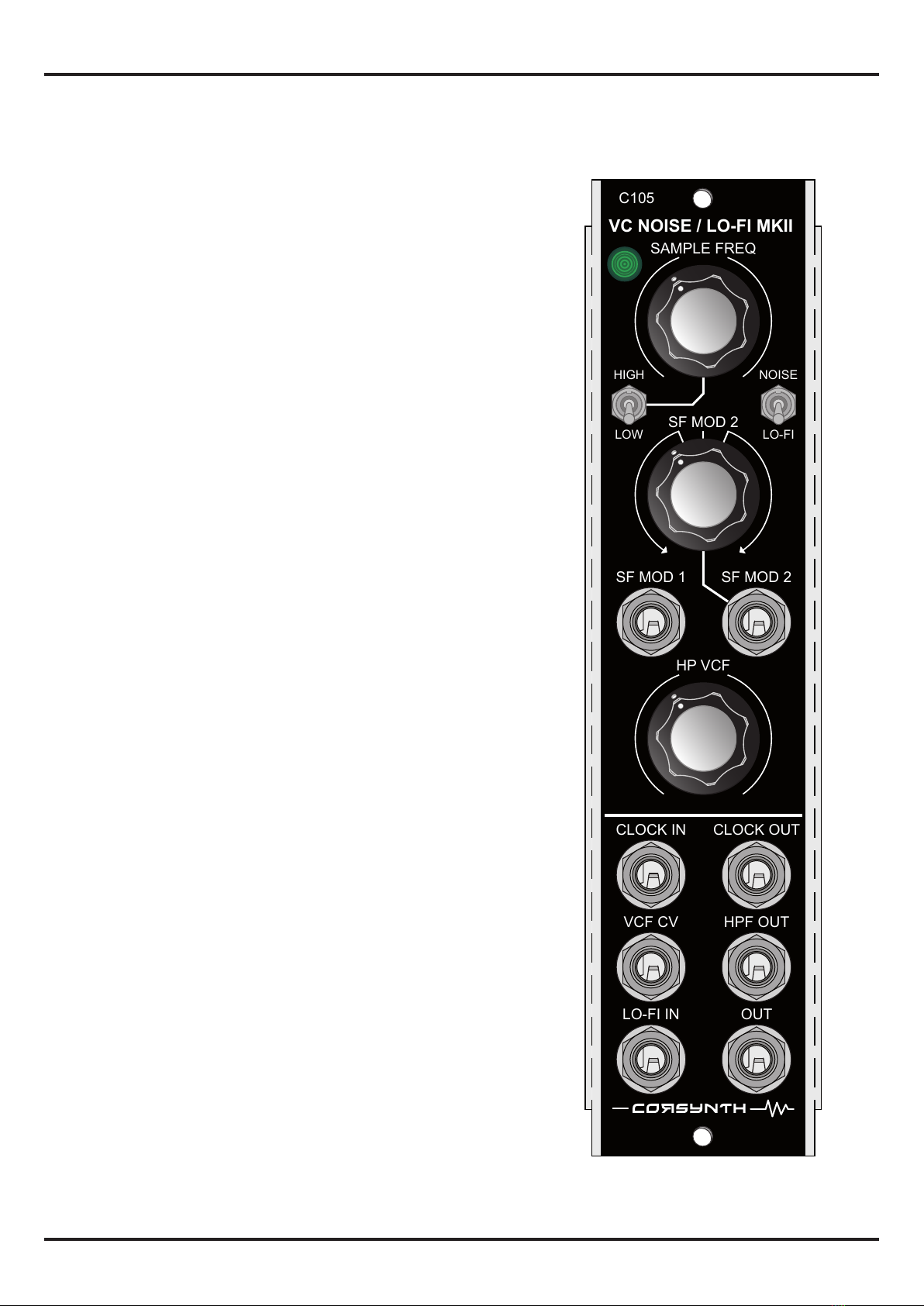
C105 VC NoIse / LO-FI MKII
1
HTTP://WWW.CORSYNTH.COM
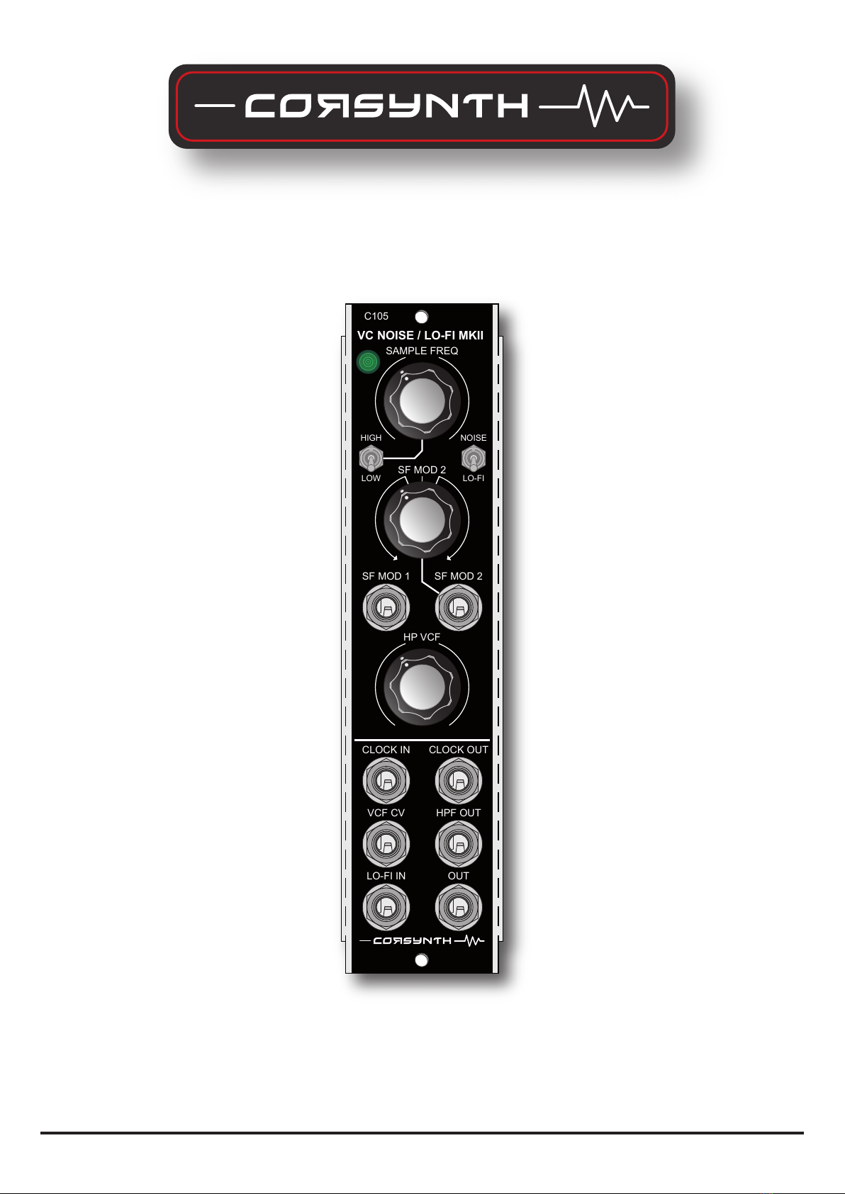
The C105 VC Noise / Lo-Fi Machine MKII is a voltage controlled
analog sample rate reducer and a VC Nosie generator. This new
MKII version expands the modules possibilities with new
features that allows this module to be used in other ways not
possible with the previous version. Now the C105 MKII can be
used like a traditional sample and hold , a voltage controlled
clock generator , a random gate / trigger generator or a 12 db
VC High pass lter and even as a square wave VCO.
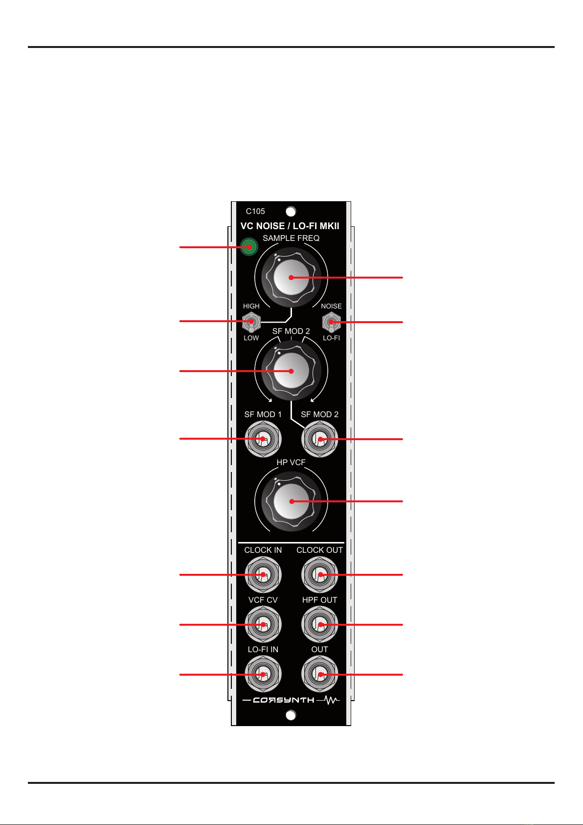
The C105 new characteristics are :
- The internal clock has a new LOW mode that allows to use it as
a traditional sample and hold.
- The module now accepts external clock signals, so it can be
synced to other modules.
- New clock output. Now the C105 can be used as a master
clock.
- The passive rst order HPF has been replaced for a voltage
controlled second order HPF.
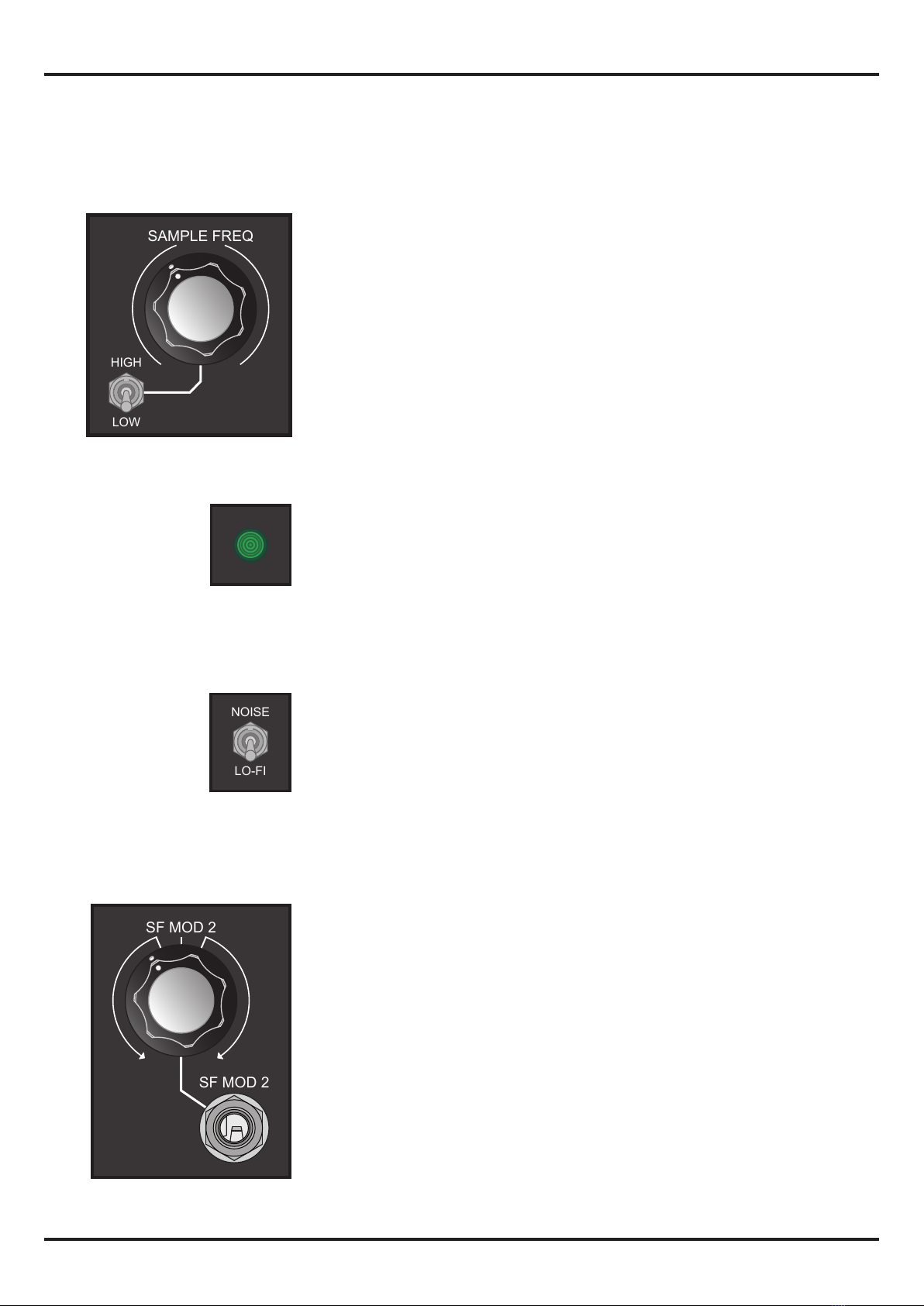
The C105 is based on a Sample and Hold with an internal clock
that goes from 0,2Hz up to 44KHz and it can be voltage
controlled. This wide frequency range and two FM inputs ( one
with a reversible attenuator ) allow to create subtle or harsh
digital and aliassing eects.
The internal noise generator in combination with the S&H
make a perfect way to create pitched noises, random voltages,
sound FXs etc.
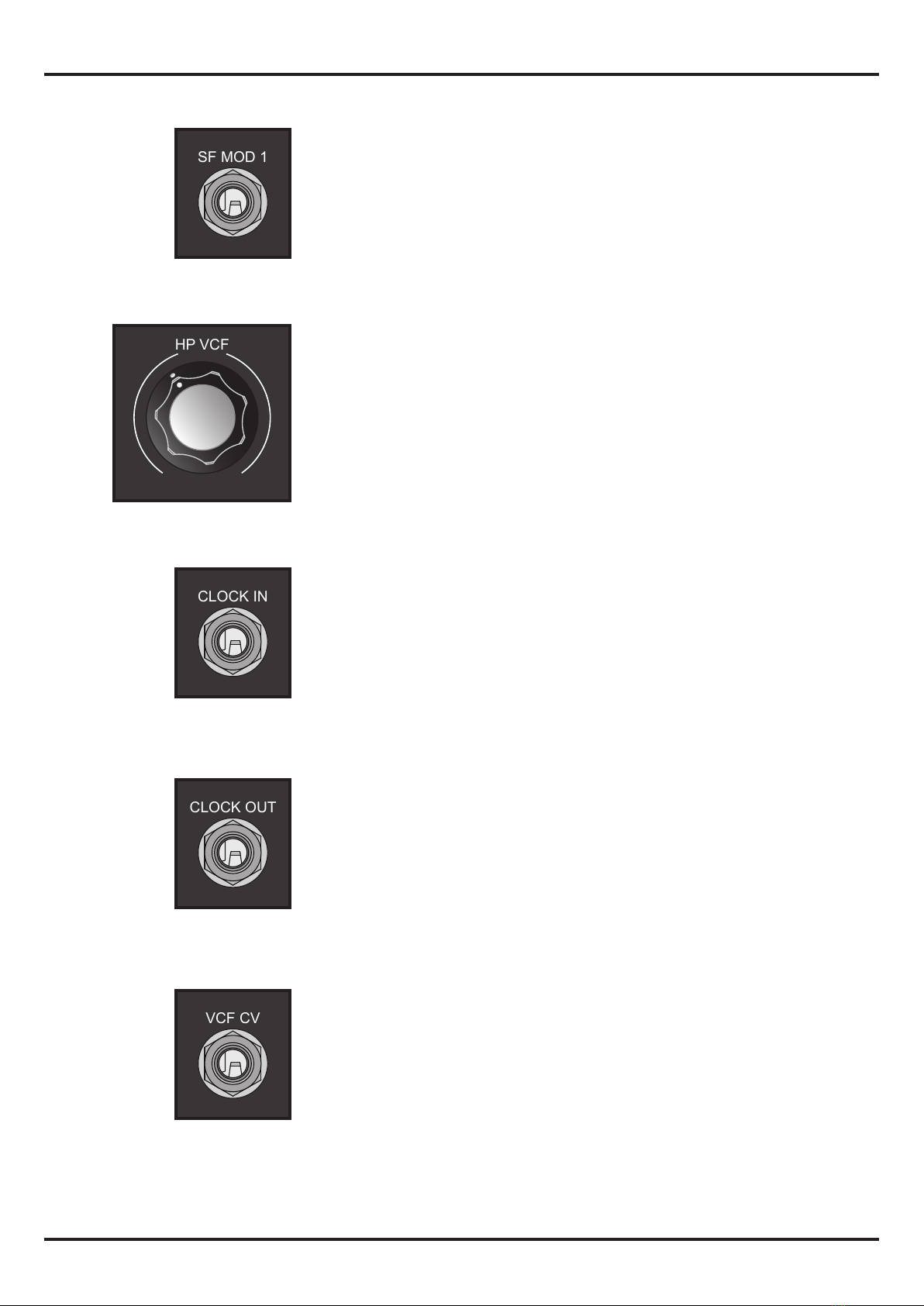
In addition, there is also a 12db VC controlled high pass lter
with an independent output.
C105 main characteristics
- Internal white noise generator.
- Voltage controlled clock with two ranges :
* Low : 0,2Hz to 125Hz
* High : 125Hz to 44KHz
- Clock input
- Clock Output
- 12db VC High Pass lter.
L-F H-F
MIN MAX
-10 +10
C105 VC NoIse / Lo-FI MKII