7
and the key be taken away. The universal joints shall be installed in good state, with
proper protective parts.
12. The chain on the protective parts of the universal joint shall be guaranteed in good
condition, in case, automatic rotation occurs.
13. All other persons shall leave the ground before connecting the driving power from the
tractor. Keep the output of the tractor at 540
RPM
.
14. Before cleaning, repairing and lubricating the machine, stop the motor and take away
the key with you.
15. When the universal joint is not connected with the tractor, they must be connected
again through the frame to protect the joint from damaging.
16. Don’t approach the machine when the machine runs.
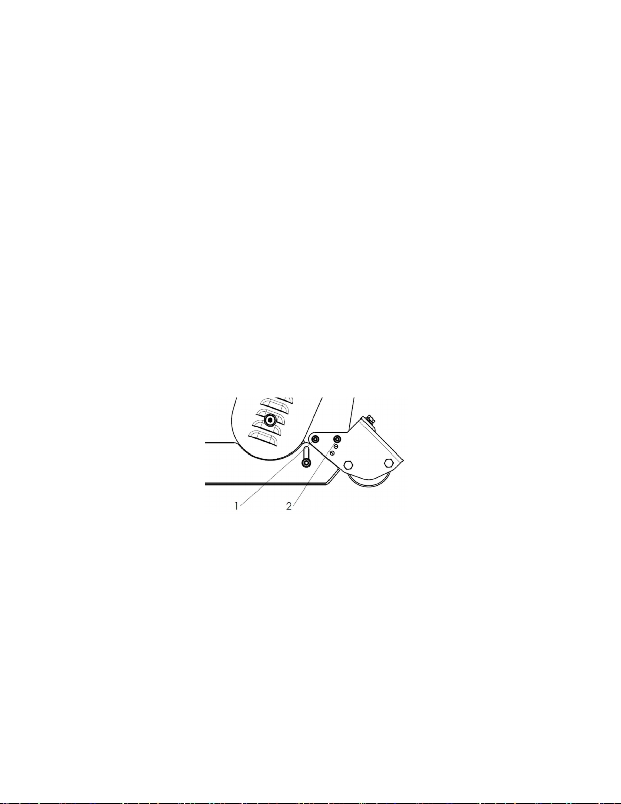
3.2 Adjusting the Height
To get the most out of your flail mower, it should be set within the recommended height.
To save fuel and power
飞
and reduce wear and tear, the cutting height must be regulated
correctly.
When adjusting the working height, loosen screw (1), remove screw (2) on both sides; The
roller height (see following drawing) can be adjusted by aligning the selected hole in the
roller support bracket at position 2. The lowest hole is the highest working height; put the
screw (2) into the selected hole; tighten screw (1) and screw (2).
3.3 Flail Mower Adjustment
1. On a flat piece of ground
,
attach the Flail Mower to the Tractor using the 3-point linkage
2. Use a solid adjustable top link
3. Lower the 3-point linkage to its lowest position
4. With the roller at the rear in contact with the ground, adjust the length of the top link so
that the lower edge at the side of the flail mower is parallel with the ground
5. Rotate the blade drum by hand so that a row of blades hangs vertically towards the
ground.
6. Measure the clearance between the bottom of the extended blades and the ground.
Minimum 50mm
Note in rough or lumpy paddocks the clearance needs to be increased to ensure