COSMO Bully SGM Series Product manual

Manual P/N: OM2812-21EN-000_19
FINISHING MOWERS
SGM- SERIES
SGM 60-72-84
OPERATOR'S AND PARTS’
MANUAL
Tirth Agro Technology Pvt. Ltd.
ISO 9001:2015 & CE Certified Company

Congratulation for purchasing your new Cosmo Bully Finishing Mower!
This mower has been designed and manufactured following all safety and quality requirements needed
for a safe and satisfactory use over time.
A careful reading of this manual will permit you to familiarize with your new equipment, and will pro-
vide you all the tools needed to use it safely.
A proper maintenance and knowledge of the safety rules of use will allow to obtain the best perfor-
mance and a long service life of the machine.
The Safety Alert Symbol used throughout this manual and on safety decals of
the machine indicates the presence of potential hazard to the operator. When
you see this symbol, be alert and carefully read the message that follows it.
The Safety Alert Symbol is used in conjunction with following Signal Words, according to the degree of
possible injuries that may result operating the implement:
DANGER
Indicates an imminently hazardous situation that, if not avoided, will result in death or serious injury.
WARNING
Indicates a potentially hazardous situation that, if not avoided, could result in death or serious injury,
and includes hazards that are exposed when guards are removed. It may also be used to alert against
unsafe practices.
CAUTION
Indicates a potentially hazardous situation that, if not avoided, may result in minor or moderate injury.
It may also be used to alert against unsafe practices.
IMPORTANT
Indicates instructions or procedures that, if not observed, can cause damage to equipment or environ-
ment.
NOTE
Indicates helpful information.
READ, UNDERSTAND, and FOLLOW the safety messages following the Safety Alert Symbol and Signal
Words. Failure to comply with safety messages could result in serious bodily injury or death.

TO THE PURCHASER
This manual contains valuable information about COSMO BULLY FINISHING MOWER. It has
been carefully prepared to give you helpful suggestions for operating, adjusting, servicing
repair parts.
Keep this manual in a convenient place for quick and easy reference. Study it carefully. You
have purchased a dependable and sturdy Finishing mower, but only by proper care and
operation can you expect to get the service and long life designed and built into it.
RIGHT-HAND AND LEFT-HAND sides are determined by watching from the tractor side.
Sometime in the future your Finishing mower may need new parts to replace those are worn
or broken. If so, go to nearest COSMO BULLY dealer and provide him the model and part
number.
Customer information
Name
Purchased from
Purchased date
Model No.
Serial No.

Index
1. ABOUT THIS MANUAL ........................................................................................................ 1
2. INTRODUCTION ................................................................................................................. 1
2.1. IDENTIFICATION ......................................................................................................................................... 1
2.2. INTENDED USE ............................................................................................................................................ 2
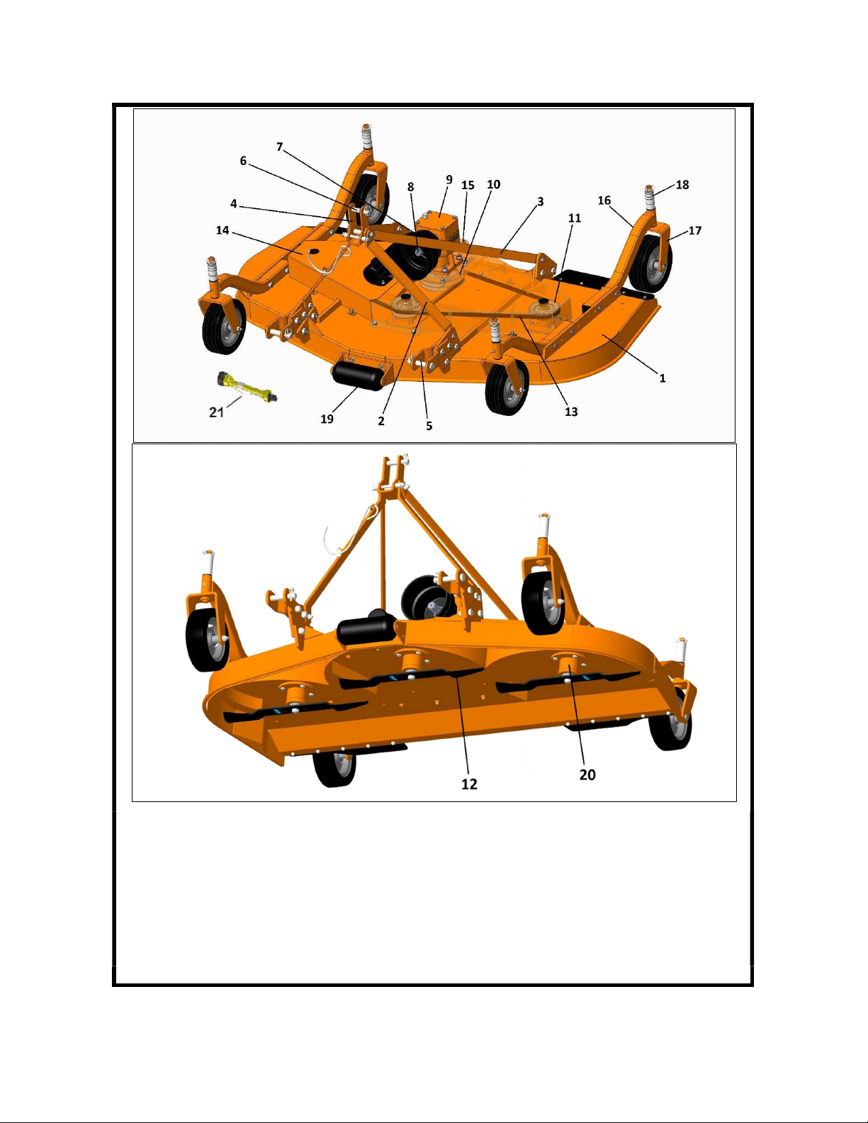
2.3. MAIN PARTS DESCRIPTION ....................................................................................................................... 3
2.4. SPECIFICATIONS ......................................................................................................................................... 4
3. SAFETY ............................................................................................................................... 5
3.1. GENERAL SAFETY INSTRUCTION .............................................................................................................. 5
3.2. EQUIPMENT SAFETY INSTRUCTIONS ....................................................................................................... 6
3.3. OPERATING SAFETY INSTRUCTION .......................................................................................................... 7
3.4. TRANSPORTING SAFETY INSTRUCTIONS................................................................................................. 8
3.5. MAINTENANCE SAFETY INSTRUCTION .................................................................................................... 9
3.6. STORAGE SAFETY INSTRUCTIONS ............................................................................................................ 9
3.7. SAFETY LABELS ........................................................................................................................................ 10
4. SET UP .............................................................................................................................. 13
4.1. CONNECTING TO THE TRACTOR ............................................................................................................. 13
4.2. DRIVELINE INSTALLATION ..................................................................................................................... 15
4.3. TRACTOR-MOWER STABILITY ................................................................................................................ 16
5. OPERATING ...................................................................................................................... 17
5.1. START UP AND REUSING .......................................................................................................................... 17
5.2. OPERATING INSTRUCTIONS .................................................................................................................... 19
5.3. ADJUSTMENTS .......................................................................................................................................... 21
5.4. STOPPING AND DISCONNECTION ........................................................................................................... 25
5.5. TRANSPORT ............................................................................................................................................... 26
6. MAINTENANCE ................................................................................................................. 27
6.1. BELTS TENSIONING .................................................................................................................................. 27
6.2. BELTS REPLACEMENT.............................................................................................................................. 29
6.3. BLADES REPLACEMENT ........................................................................................................................... 29
6.4. GEARBOX LUBRICATION .......................................................................................................................... 31
6.5. SPINDLE SHAFTS LUBRICATION ............................................................................................................. 32
6.6. WHEELS AND WHEEL SUPPORTS LUBRICATION .................................................................................. 32
6.7. DRIVESHAFT MAINTENANCE .................................................................................................................. 33
7. STORAGE .......................................................................................................................... 33
8. SCRAPPING ...................................................................................................................... 33
9. TROUBLESHOOTING ........................................................................................................ 34
10. TORQUE VALUES TABLE .............................................................................................. 35
11. WARRANTY .................................................................................................................. 36
12. SPARE PARTS ............................................................................................................... 38
13. "EC " DECLARATION OF CONFORMITY ......................................................................... 39

1. ABOUT THIS MANUAL
The operator must read the manual for a correct understanding of the hazards that may present when
operating the mower, as well as for obtain optimum performance from the machine.
The manual is part of the machine, it must be kept in good condition and remain with the machine even
in case of resale, until its demolition. In case of loss or damage, request a new copy to the Manufacturer
or your Dealer.
The information, descriptions and illustrations in this manual describe the state of the product at the
time of its publication, and may not reflect the product in the future.
The Manufacturer reserve the right to make design improvements or changes in specifications without
incurring in any obligation to install them on units previously sold.
Text, illustrations and drawings of this manual cannot be disclosed or transmitted, in whole or in part,
to third parties without the written permission of the Manufacturer. All rights are reserved.
2. INTRODUCTION
2.1. IDENTIFICATION
Each mower is provided with a plate for unique identification (see picture below), showing the CE mark-
ing together with following information:
• Manufacturer name and address
• Type of machine ("TYPE")
• Model of machine ("MODEL")
• Serial number ("SERIAL No.")
• Construction year ("YEAR")
• Machine weight ("MASS")
• Speed required at Implement Input Connection ("INPUT").
It's recommended to note down all data shown on the plate.
Any request for assistance or information regarding the machine must be directed to the Manufacturer
or Dealer always referring to the model and serial number as shown on the plate affixed to the machine.

2.2. INTENDED USE
The SGM-series Finishing mowers are specifically designed for lawn and grass professional mowing and
maintenance of areas like private lawns, parks, airports, hospital grounds, schools, highways, golf
courses etc.
The SGM mowers are NOT designed for rough conditions or heavy weed mowing.
The SGM mowers can be either tractor front or rear mounted on universal three-point hitch, and are
driven by the tractor power through a PTO driveshaft connected to a speed multiplier gearbox. The
power is transmitted by means of two belts from a pulley coupled to the gearbox shaft to three pulleys
coupled to individual spindle shafts. Each shaft is equipped with a suction type blade turning at a high
tip speed for best results in mowing.
The mowers are provided with 4 swivel wheels that allow to follow the contour of the ground, giving a
precise and level cut even in undulating conditions.
The tractors used to operate the SGM-series mowers must have the following requirements:
Hitch Category: 3-point, Category 1 (ISO 730 standard)
PTO: 540 RPM, 6 – SPLINE, 13/8 “26
Horsepower: As per technical specification.
DANGER
Any use of the machine other than the intended use is non-intended use, and is to be considered as
unauthorized and dangerous. The manufacturer assumes no liability for damage resulting from non-
intended use.

2.3. MAIN PARTS DESCRIPTION
1.
Mower deck
2. Top hitch support
3. Top hitch arm
4. Top hitch link
5. Lower hitch pin
6. Upper hitch pin
7. PTO shield
8. Implement Input Connection
9. Gearbox multiplier
10. Driving pulley
11.
Driven pulley
12. Blade
13. Transmission belt
14. Belt cover
15. Belt tensioner screw
16. Wheel arm
17. Swivel wheel
18. Height adjusting spacers
19. Front roller
20. Blade spindle
21. Cardan driveshaft
NOTE
To make the illustrations more clear, some images of this manual may refer to machines lacking of

some components (e.g. belt cover).
2.4. SPECIFICATIONS
MODEL SGM 48^
(1.2M)
SGM 60
(1.5M)
SGM 72
(1.8M)
SGM 84
(2.1M)
Overall dimensions cm 136x134x75 163x147x75 192x152x75 225x173x75
Cutting width
cm 122 150 180 213
inches 48'' 60'' 72'' 84''
Tractor power HP 20-50
3-point Hitch type - Category 1 (ISO 730 standard)
PTO Input speed rpm 540
Cutting height
mm 19 - 110
inches 3/4'' - 4 1/3''
PTO driveshaft - ASAE Cat. 3
Deck thickness mm 4,5
Wheels
- - Air
- Air 11x4-5 Air 11x4-5 Air 11x4-5 Air 11x4-5
- Solid 10x3.25 Solid 10x3.25 Solid 10x3.25 Solid 10x3.25
Belts (number and type) - 2 SPB type
Number of blades - 3
Blade size mm 6x60x424 6x60x515.5 6x60x616 6x60x730
Blade overlap mm 25
Blade shaft speed rpm 3130 2648 2236 2027
Blade tip speed fpm 13,681 14,074 14,192 15,275
Spindle type - with greaseable ball bearings
Spindle bearings - Bearing 6206
Front roller - Standard
Unit Weight (*) Kg/BS 205/452 228/502 253/558 302/666
(^) Indent orders only. (*) driveshaft excluded.
Note: - Spindle bearing 6205 is also available as per requites.

3. SAFETY
Proper use of the equipment, a strict observance of the safety messages listed below and application of
all reasonable practices to avoid any risks, prevents accidents or injury, allows the machine working
better and longer, and minimize the failures.
The manufacturer assumes no liability for any damage resulting from not applying the behavioral rules
indicated into the manual.
3.1. GENERAL SAFETY INSTRUCTION
DANGER
The machine must be used only by authorized and well trained operators. The operator must have read
and understood the instructions of this manual, it must make adequate preparation for the proper use
of the machine and must hold a driving license. In case of doubt about the use of the machine and/or the
interpretation of this manual, the operator must contact the Manufacturer or the Dealer.
WARNING
The manual must always remain with the machine. In case of loss or damage, request a new copy to the
Manufacturer or your Dealer.
WARNING
Follow strictly the rules prescribed by the safety pictograms applied to the machine.
WARNING
Be sure that all safety pictograms are legible. If pictograms are worn, they must be replaced with others
obtained from the Manufacturer, and placed in the position indicated by this manual.
DANGER
Before using the machine, make sure that all safety devices are installed and in good working conditions.
In case of damages of shields, replace them immediately.
DANGER
Is absolutely forbidden to remove or alter safety devices.
DANGER
Before starting, and during operation of the mower, make sure there are no people or animals in the
operation area: the machine can project material from the back, with risks of serious injury or death.
DANGER
Pay maximum attention to avoid any accidental contact with rotating parts of the machine.
DANGER
During operation, adjustment, maintenance, repairing or transportation of the machine, the operator
must always use appropriate Personal Protective Equipment (PPE).
DANGER
Do not operate the implement while wearing loose fitting clothing that can give rise to entanglement in
parts of the machine.
DANGER
Do not operate the implement when tired, not in good condition or under the influence of alcohol or
drugs.

CAUTION
If the use of the machine is required at night or in conditions of reduced visibility, use the lighting system
of the tractor and possibly an auxiliary lighting system.
3.2. EQUIPMENT SAFETY INSTRUCTIONS
WARNING
Use the mower for its intended purpose only. Improper use can damage the implement and cause seri-
ous injury to persons, animals, or death.
DANGER
The machine should be used by a single operator driving the tractor.
WARNING
Any unauthorized modification of the machine may cause problems in safety and relieves the Manufac-
turer from any liability for damages or injuries that may result to operators, third parties and objects.
WARNING
Before using the machine, familiarize yourself with its controls and its working capacity.
WARNING
Do not leave the mower unattended with tractor engine running.
WARNING
Keep the machine clean from debris and foreign objects which may damage functioning or cause injury.
WARNING
Do not use the machine if the category of the connecting pins of the mower does not match that of the
tractor hitch system.
WARNING
Do not use the machine with missing bolts, screws, pins or safety pins.
WARNING
Never use the machine to transport or lift people, animals or objects.
WARNING
Make certain, by adding front ballast, that at least 20% of the total weight (tractor, implement and bal-
last) is on the front axle of the tractor, to ensure stability.
WARNING
Before engaging the tractor PTO, make sure the tractor PTO speed is set as required for the mower (540
rpm). Do not over speed PTO or machine breakage may result.
DANGER
Do not operate the mower if the driveshaft is damaged. The driveshaft could be subject to breakage
during operation, causing serious injury or death. Remove the driveshaft and replace it with an undam-
aged.
DANGER
With mower disconnected from tractor, rest the driveline on the provided support of the mower.

3.3. OPERATING SAFETY INSTRUCTION
WARNING
Before using the machine, be sure to have cleared the operating area from obstacles (stones,
branches, debris, etc...). Mark all the obstacles that cannot be eliminated (e.g. by means flags).
DANGER
Never engage the tractor PTO in the presence of people close to the driveshaft. The body, hair or cloth-
ing of a person can get caught in rotating parts, causing serious injury or death.
DANGER
Before engaging the PTO and during all operations, make sure that no person or animal is in imme-
diate area of action of the machine. Never use the mower if people are in his working area.
DANGER
It's absolutely forbidden to stand near the mower with moving parts.
WARNING
The operator must operate mower lifting/lowering only from the driving seat of the tractor. Do not per-
form lifting maneuvers on side or behind the tractor.
DANGER
The presence of steep slopes may cause instability to the system tractor and mower, with risk of tipping
and consequent serious injury or death hazard. Consult the manual for the tractor to determine the
maximum slope that the tractor is able to deal with.
DANGER
Never engage the PTO until the mower is in the down position and resting on the ground. Never raise
the mower until all blades have come to a complete stop. The machine might throw objects at high speed,
causing serious injury or death.
WARNING
Never leave the driver's seat when the tractor is turned on. Before leaving the tractor, lower the mower
to the ground, disengage the PTO, insert the parking brake, stop engine and remove the key from the
control panel.
DANGER
The PTO shields of tractor and implement side, the driveshaft shielding and the driveshaft retaining
chains must be properly installed and in good condition, to avoid risk of entanglement with serious in-
jury or death.
DANGER
Before engaging the PTO of the tractor, always make sure that the driveshaft is correctly installed, with
clamping elements properly connected both to tractor side and to implement side.
WARNING
Only operate PTO at 540 rpm. Know how to stop tractor and mower quickly in an emergency.
WARNING

Stop operating immediately if blades strike a foreign object. Repair all damage and make certain spin-
dles and blades are in good condition before restarting operation.
WARNING
Always disengage the tractor PTO when the driveshaft exceeds an angle of 10 degrees up or down while
operating. An excessive angle with driveshaft rotating can break the driveshaft and cause flying projec-
tiles.
CAUTION
Prolonged use of the mower can cause overheating of the gearbox. Do not touch the gearbox during use
and immediately after, it could be extremely hot and cause severe burn.
WARNING
All adjustment operations on the mower must be performed by qualified and trained operators, with
the tractor engine off, the PTO disengaged, the mower lowered to the ground or on security stands, the
ignition key off and the parking brake set.
3.4. TRANSPORTING SAFETY INSTRUCTIONS
WARNING
Before transporting, determine the stopping characteristics of the tractor and implement.
WARNING
Transport only at speeds where you can maintain control of the equipment.
WARNING
When driving on roads, the implement must be in transport position adequately raised from the road
surface, with tractor lifting hydraulics locked so that the mower cannot be lowered accidentally.
DANGER
The implement may be wider than the tractor. Pay attention during transporting to persons, animals or
obstacles exposed.
WARNING
When turning, use extreme care and reduce tractor speed.
WARNING
Do not operate the tractor with weak or faulty brakes or worn tires.
CAUTION
Always use tractor lighting system and auxiliary lighting system for an adequate warning to operators
of other vehicles, especially when transporting at night or in conditions of reduced visibility.
DANGER
In case of mower lifting, make sure that the lifting device chosen is suitable to perform the operation
safely, and use only the lifting points prescribed on mower.

3.5. MAINTENANCE SAFETY INSTRUCTION
WARNING
All maintenance and repairing operations must be performed by qualified and trained operators, with
the tractor engine off, the PTO disengaged, the mower lowered to the ground or on security stands, the
parking brake and the set ignition key off. Secure blocking prevents equipment from dropping due to
hydraulic leak down, hydraulic system failures, or mechanical component failures.
WARNING
Perform repairs and replacements necessary to the mower using only original spare parts provided
by the manufacturer or your Dealer.
DANGER
Perform maintenance operations always using appropriate Personal Protective Equipment (protective
eye glasses, hard hat, hearing protection, safety shoes, overall and work gloves, filter mask).
CAUTION
Before any maintenance operation, make sure that the parts which may become hot during use (gear
box) have cooled.
WARNING
Do not perform repairs that you do not know. Always follow the manual instructions and in case of doubt
contact the Manufacturer or your Dealer.
DANGER
Do not swallow fuels or lubricants. In case of accidental contact with eyes, rinse well with water and
consult a doctor.
3.6. STORAGE SAFETY INSTRUCTIONS
WARNING
Never leave the tractor unattended with the mower in lifted position. Accidental operation of lifting
lever or a hydraulic failure may cause sudden drop of unit with injury or death by crushing.
DANGER
Following operation, or before unhooking the mower, stop the tractor, set the brakes, disengage the
PTO, lower the attached mower to the ground, shut off the engine, remove the ignition key and wait for
all moving parts to stop.
WARNING
Make sure all parked machines are on a hard, level surface and engage all safety devices.
CAUTION
Store the unit in an area away from human activity.

3.7. SAFETY LABELS
The safety labels applied on the machine give fundamental information for using the machine
safely.
Make sure safety labels are in good conditions. If pictograms are worn, they must be replaced with oth-
ers obtained from the Manufacturer and placed in the position indicated by this manual.
Make sure the safety labels are legible. If necessary, wipe them by a cloth, with soap and water.
SAFETY LABELS POSITION AND DESCRIPTION
SR.
NO. SPARE CODE
DECALS DESCRIPTION
1 D1090
Carefully read the operator's manu-
als of mower, tractor and cardan
shaft before using the machine.

2 D1038
Disengage the PTO, turn off the trac-
tor engine, remove the key and en-
sure that all rotating parts have
stopped before approaching the im-
plement. Read the operator's manual
before performing any maintenance
operation.
3 D1095
Thrown or flying object hazard. Keep
a safe distance from the machine.
4 D1132
Rotating blades: Severing of lower
limbs hazard. Keep a safe distance
from the machine.
5 D1078
Cutting of fingers or hand hazard.
Wait until all machine components
have completely stopped before
touching them.
6 D1079
Rotating gear: fingers or hand entan-
glement hazard. Do not open or re-
move safety shields while engine is
running.

7 D1097
Crushing hazard. stay clear of draft
link lifting range while in operation.
8 D1098
Implement input driveline: body en-
tanglement hazard. Do not open or
remove safety shields while engine is
running.
9 D1099
Before engaging the tractor PTO,
check that rpm rate and sense of ro-
tation are those prescribed for the
implement.
10 D1082
Always engaging clothing and equip-
ment appropriate for the job: Hear-
ing protection, safety shoes, safety
gloves, safety glasses and overall.
11 D1007
Oil filling point
12 D1008
Greasing point

13 D1108
CE LOGO
14 D1123
ROTATING DRIVELINE (COVER)
15 D1124
ROTATING DRIVELINE (TUBE)
4. SET UP
The mower is delivered equipped with a driveshaft and related operating manual.
When the machine is delivered, check that there is no damage to the mower or driveshaft. In case of
damage or missing parts immediately notify the Manufacturer or your Dealer.
Because of his size, the mower could be delivered with some parts disassembled. In this case, the assem-
bly of such parts is an owner's task, and must be carefully performed with reference to the layout tables
of the Spare parts section.
ATTENTION
For proper tightening torques of bolts and screws, refer to the section Torque values table of the manual.
4.1. CONNECTING TO THE TRACTOR
The SGM mowers are designed to be mounted on tractors up to 50 hp equipped with 3-point Hitch Cat-
egory 1 (ISO 730 standard).
WARNING
Check the tractor PTO to ensure it is set at 540 rpm and turns clockwise.
WARNING
Before connect the implement to the tractor, make sure that tractor and mower are on a flat, stable and
dry surface.

To connect the mower to the tractor the operator must do the following:
drive the tractor in reverse up to the mower, in order to slip the tractor hitch arms over the hitch pins
of the mower (see picture below);
set the tractor's parking brake, stop engine, remove the ignition key and get off the tractor;
connect the lifting arms of the tractor to the lower hitches of the mower, through the use of the pins
and relative safety split pins;
adjust the tractor sway blocks or chains to remove all side movement;
connect the tractor top link to the mower top link plate through the relative pin and safety split pin.
The 3-point hitch system of the mower is designed to have a limited front to back flotation when
mowing on uneven terrain. Adjust the tractor’s top link until the top link plate of the mower is in
vertical position respect to the deck (see picture below), in order to allow the mower to follow the
ground contour during mowing operation.
check the interference between mower's front wheel arms and tractor wheels. If there is interference,
adjust the position of the mower front wheel arms according to instruction described in section Wheel
arms adjustment;
proceed with the driveline connection (see Section Driveline installation).

4.2. DRIVELINE INSTALLATION
Before installing the driveshaft, the operator must read the manuals of the tractor and driveshaft, check-
ing in particular that rpm and direction of rotation of the PTO tractor match those of the mower.
If the direction of rotation of the PTO tractor does not match that of the mower, contact the Manufacturer
or your Dealer.
To connect the driveshaft to the tractor and implement, the operator must:
park tractor and mower on a flat surface, with parking brake set, engine off, and ignition key removed;
check that driveshaft, mower and tractor safety shields are in good condition, otherwise provide for
their replacement;
remove the PTO shield of the mower through the fixing screws;
insert the driveline yoke on the mower PTO by first lining up the splines, then ensure its tight-
ening onto the shaft through its fastener/snap pin;
replace the PTO shield of the mower through the fixing screws;
insert the driveline yoke on the tractor PTO, then ensure its tightening onto shaft through its fas-
tener/snap pin;
hook to the tractor and mower the two retaining chains of the driveline shielding, to prevent shielding
rotation during functioning of the machine. The chains should not be too tight.
WARNING
The driveline must not exceed an angle of 15 degrees up or down while operating. Exceeding this angle
with driveline rotating can break the driveline and cause safety hazard to operator and bystanders.
Always work with the driveline as straight as possible. This will prolong life of driveline and that of its
components, avoiding premature breakdowns.
Driveline Length Check
Before operating the mower, ensure that the size of driveshaft is adequate. The driveshaft supplied with
the machine has a standard length, therefore it may need an adaptation of the length, depending of the
tractor which the mower is combined.
The length of the driveshaft must be such to:
avoid bottom out of the transmission tubes, when the driveshaft is in compressed position (when the
mower is raised up off the ground);
ensure an overlapping of the transmission tubes enough to transmit the torque required, when the
driveshaft is in max extension (when the mower is in its lowest position in the ground).
When the driveshaft is at its minimum length (max compressed position), there must be at least a 2 cm
of distance between the ends of each transmission tube and the yokes side.
When the driveshaft is at its maximum operational extension, there must be an overlap between the
tubes profiles of 15 cm at least.

A driveshaft too long may cause structural damages to the tractor and machine. If the driveshaft is too
long, it may be adapted by removing it and shortening the tubes according to the instructions provided
by the Manufacturer in its use and maintenance manual.
A driveshaft too short can cause disengage of the tubes during operation, with severe hazard for the
operator and structural damage to the tractor and machine. If the driveshaft is too short, it must be
replaced with a longer one. In this case contact the Manufacturer or your Dealer.
IMPORTANT
before operating the mower, the first time, or before reusing the mower after a long term storage,
make sure that the driveshaft is lubricated in accordance with how indicated in his own instruction
booklet;
always engage the tractor PTO at low rpm to minimize the effect of the peak torque on the driveline
and the machine.
4.3. TRACTOR-MOWER STABILITY
Before connecting the machine to the tractor is required to check the stability of the tractor-machine
system, in order to determine the ballast to apply to the front of the tractor, to ensure adequate distri-
bution of the weight on the axles when the implement is in lifted position (e.g. for transportation).
In order to assure the stability, it is necessary that the following relations are verified (see table below
for definitions):
1) M x (S1+S2) ≤ 0.2 x T x i + Z x (d+i)
2) M ≤ 0.3T
Consequently, the minimum ballast required is:
Zmin = (M x (S1+S2) - 0.2 x T x i)/(d+i).
To determine the appropriate characteristics of the ballast, refer to the manual of the tractor.
This manual suits for next models
3
Table of contents
Other COSMO Bully Lawn Mower manuals