Cospolich F41-2M-SN-MLR User manual

Technical Manual
Installation, Operation, and
Maintenance Instructions
Cospolich Refrigerator Company, Inc.
Destrehan, LA 70047
800-423-7761
Modular Freezer
F41-2M-SN-MLR
www.Cospolich.com

Chapter 1
General Information
1.1 Introduction
This technical manual provides information for the installation, operation,
maintenance, and inspection of this unit manufactured by Cospolich, Inc., Norco,
Louisiana. A complete parts breakdown is also provided.
1.2 Scope of the Manual
This manual provides sufficient information for maintenance of the equipment.
1.3 Equipment Description
The unit consists of the following parts:
a. Storage compartment – The insulated food storage compartment is
clear storage area. Included in this area are the adjustable shelves, an
interior light (for refrigerators), and the cooling coil.
b. Doors – Access to the storage compartment is through a hinge-
mounted, insulated door(s). The door is fully “gasketed” to provide a
tight seal.
c. Condensing Unit Compartment – This area contains the condensing
unit(s) along with the necessary controls and other components.
d. Evaporator Coil – The evaporator coil is located in the storage
compartment and is responsible for distributing the cold air associated
with the refrigeration system.
e. Cabinet – The cabinet is the enclosure in which all of the above
mentioned items are housed.
1.4 Equipment Supplied
The unit is shipped from the factory fully assembled except for the adjustable
shelving that will require positioning on the pilaster standards as needed. The
complete assembly is palletized and crated to minimize the possibility of damage
1-1

in shipping and storage. See Appendix A for assembly and installation
instructions for Modular units.
Manufacturer: Cospolich, Inc.
Destrehan, Louisiana 70047
Type: Marine Freezer Unit
Model Number: F41-2M-SN-MLR
Refrigerant: R404A
Purpose: Storage of Frozen Food Items
Power Supply: 115 Volts AC
Operating Current: 14.3 Amps
Maximum Power Demand: 20 Amps
Drain Requirements: None
Shipping Weight: 765 lbs.
Operating Weight: 708 lbs.
Volume (crated): 84 cu. Ft.
T
Ta
ab
bl
le
e
1
1.
.1
1
–
–
L
Le
ea
ad
di
in
ng
g
P
Pa
ar
rt
ti
ic
cu
ul
la
ar
rs
s
1-2

F
Fi
ig
gu
ur
re
e
1
1.
.1
1
–
–
G
Ge
en
ne
er
ra
al
l
A
Ar
rr
ra
an
ng
ge
em
me
en
nt
t
D
Dr
ra
aw
wi
in
ng
g
1-3

Chapter 7
Parts Lists
7.1 Introduction
This section of the manual contains lists of replaceable parts. Each of the tables
contains a list of removable parts associated with an assembly of the cabinet or
refrigeration system. No parts identification has been provided for details of
permanently assembled items or those that are not suitable for field repair.
7.2 Source Codes
The sources for some items are shown in Table 7.1 below.
Code Number
Name
Address
14852
Bohn Heat Transfer
Danville, IL 61932
32761
Kason Industries
Shenandoah, GA 30265
50992
Ranco Controls
St. Louis, MO 63143
78462
Spporlan Valve
St. Louis, MO 63143
14569
Copeland Corporation
Sidney, OH 45365
17529
Watsco
Hialeah, FL 33010
59431
Tecumseh Products
Tecumseh, MI 49286
49048
Miljoco Corporation
Eastpointe, MI 48021
45020
Nashville Wire Products
Nashville, TN 37202
79264
Jean's Extrusions, Inc.
Salem, IN 47167
2K223
Refrigeration Hardware
Sun Valley, CA 91353
87518
Standard Keil, Inc.
Allenwood, NJ 08720
60886
Idec Corporation
Sunnyvale, CA 94089
19220
Eberhard, Inc.
Cleveland, OH 44136
66682
Cospolich, Inc.
Norco, LA 70079
Table 7.2, on the following page, is a parts list of special tools required for routine
service.
T
Ta
ab
bl
le
e
7
7.
.1
1
–
–
V
Ve
en
nd
do
or
r
S
So
ou
ur
rc
ce
e
C
Co
od
de
es
s
7-1

Part Number
Description
Quantity
R1412
Refrigerant service gauges with hoses
1
VA70264
Service valve wrench
1
50992
Refrigerant
30 lbs.
T
Ta
ab
bl
le
e
7
7.
.2
2
–
–
P
Pa
ar
rt
ts
s
L
Li
is
st
t
–
–
S
Sp
pe
ec
ci
ia
al
l
T
To
oo
ol
ls
s
L
Li
is
st
t
7-2

Parts List - Cabinet
F41-2M-SN-MLR
Item
Cosp #
Mfg #
Vendor
Qty
Latch
HXLH06
172BC
Kason
2
Hinge
HXHE02
217
Kason
5
Thermometer
RWTM01C
V20362002
Milijoco
1
Pilaster #1
HXSD36
65
Kason
6
Pilaster #2
HXSD48
65
Kason
2
Pilaster Clip
HXCS01
66
Kason
28
Shelves
SSW22BX23B
-
Cospolich
7
Gasket #1
GG64MV
-
Cospolich
1
Gasket #2
GG65MV
-
Cospolich
1
Mullion Heater #1
L1HR141H
-
Cospolich
1
Mullion Heater #2
L1HR167H
-
Cospolich
1
Parts List -
Refrigeration
F41-2M-SN-MLR
Item
Cosp #
Mfg #
Vendor
Qty
Evaporator Coil Assy
RWE040
TA23SG
Heatcraft
1
Evaporator Motor
RWEM03
25300701
Heatcraft
1
Evaporator Fan
RWE5101B
5101B
Heatcraft
1
Expansion Valve
RWEV30
FS 1/2 Z
Sporlan
1
Thermostat
RWTT02
T6031A-1029
Honeywell
1
Defrost Timer
RWDT01
8145-00
Paragon
1
Condensing Unit
RUT520-2
M4CF-0050-IAA-212
Copeland
1
Compressor
RUT521
RS43C1E-IAA-100
Copeland
1
Condenser
RWCD37
066-0303-00
Copeland
1
Condenser Fan Blade
RWFB08
083-0130-00
Copeland
1
Condenser Fan Motor
RWCM28
050-0259-02
Copeland
1
Receiver
RWRT12
577-0346-02
Copeland
1
Start Capacitor
RWCP02
014-0008-74
Copeland
1
Run Capacitor
-
-
-
-
Relay
RWRLY02
040-0102-00
Copeland
1
Overload
RWOVL42
071-0329-15
Copeland
1
Filter Dryer
RWFD02
C-052-S
Sporlan
1
Sight Glass
RWSG01
SG-114
Watsco
1
Pressure Control
RWPL02
010-1483
Ranco
1
Power Control Switch
LWTS01
-
Cospolich
1
Terminal Box Assy
LT-001
-
Cospolich
1
Quick Connect Fitting 1/4"
RWQF0048
5500-4-8
Aeroquip
2
Quick Connect Fitting 3/8"
RWQF0068
5500-6-8
Aeroquip
2
Wire Harness
MT-003
-
-
1
Power Card
MT-004
-
-
1
T
Ta
ab
bl
le
e
7
7.
.3
3
–
–
P
Pa
ar
rt
ts
s
L
Li
is
st
t
7-3

Chapter 9
Electrical and Mechanical
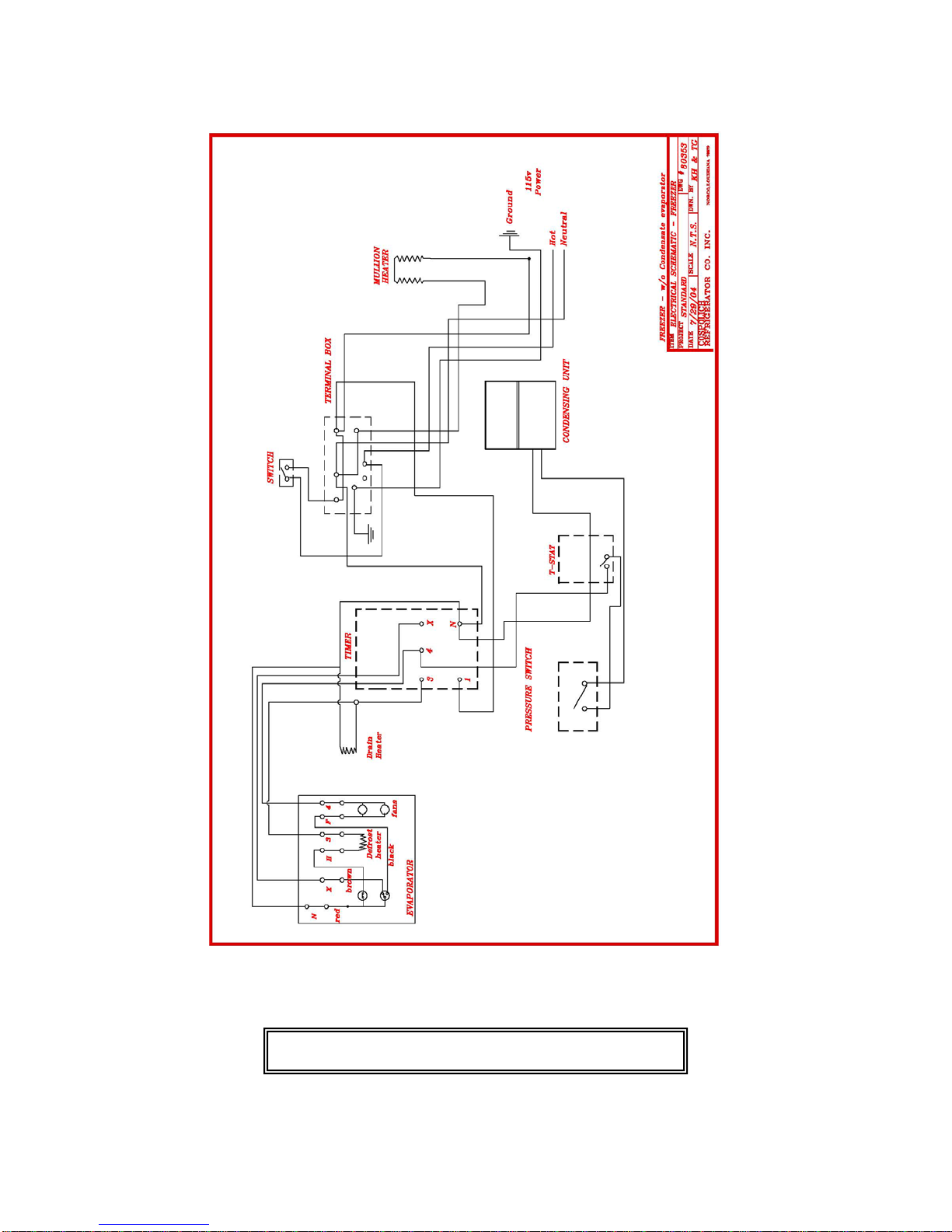
9.1 Introduction
This section of the manual contains drawings and schematics of the electrical and
mechanical piping systems.
9.2 Electrical Abbreviations and Terminology
a. RLA – Rated Load Amperage
1. Rated load amps is a measure of the current drawn by a compressor
when operated at compressor manufacturer rating conditions at
nominal voltage. This value is listed at U.L. and C.S.A. as “RLA”. It
is in agreement with the N.E.C. definition that the RLA be the current
draw when the compressor is delivering rated output.
b. LRA – Locked Rotor Amperage
1. The locked rotor amps of a compressor is the current value recorded
three seconds after rated voltage is applied under locked rotor
conditions from a 75 degree Fahrenheit motor soakout temperature
(The voltage drop is to be predetermined and adjusted accordingly
prior to testing). This value appears on the compressor serial plate and
on all compressor statistics sheets.
2. It may be well to note that the practice in the past was to show an
additional column marked, “LRA U.L. Test Report”. This is no longer
needed since the U.L. investigation work, regarding component rating,
will be guided by the compressor manufacturer’s published value.
c. MCC – Maximum Continuous Current
1. Maximum continuous current is a limiting ampere value that must not
be greater than 156% of the RLA of the compressor as marked on the
nameplate of the particular unit into which that compressor is applied.
9-1

Refrigerant: R-12
Cabinet
Ambient
Suction Pressure
Head Pressure
-5 degrees F (Fre.)
90 degrees F
0-10 lbs.
120-150 lbs.
37 degrees F (Ref.)
90 degrees F
18-35 lbs.
120-150 lbs.
Refrigerant: R-22
Cabinet
Ambient
Suction Pressure
Head Pressure
-5 degrees F (Fre.)
90 degrees F
10-15 lbs.
200-250 lbs.
37 degrees F (Ref.)
90 degrees F
37-67 lbs.
200-250 lbs.
Refrigerant: 134A
Cabinet
Ambient
Suction Pressure
Head Pressure
-5 degrees F (Fre.)
90 degrees F
-5-10 lbs.
120-150 lbs.
37 degrees F (Ref.)
90 degrees F
16-37 lbs.
120-150 lbs.
Refrigerant: 404A
Cabinet
Ambient
Suction Pressure
Head Pressure
-5 degrees F (Fre.)
90 degrees F
15-20 lbs.
250-300 lbs.
37 degrees F (Ref.)
90 degrees F
68-84 lbs.
250-300 lbs.
T
Ta
ab
bl
le
e
9
9.
.1
1
–
–
O
Op
pe
er
ra
at
ti
in
ng
g
P
Pr
re
es
ss
su
ur
re
es
s
9-2

F
Fi
ig
gu
ur
re
e
9
9.
.1
1
–
–
E
El
le
ec
ct
tr
ri
ic
ca
al
l
S
Sc
ch
he
em
ma
at
ti
ic
c
9-3

F
Fi
ig
gu
ur
re
e
9
9.
.2
2
–
–
R
Re
ef
fr
ri
ig
ge
er
ra
at
ti
io
on
n
P
Pi
ip
pi
in
ng
g
S
Sc
ch
he
em
ma
at
ti
ic
c
9-4
Table of contents