COT NM-108 BC User manual

NIGHT VISION MODULE
COT NM-108 BC
Modern Optical Tec nologies

Safety Summary
Before operating this product, carefully read and study this Operation and Maintenance Manual.
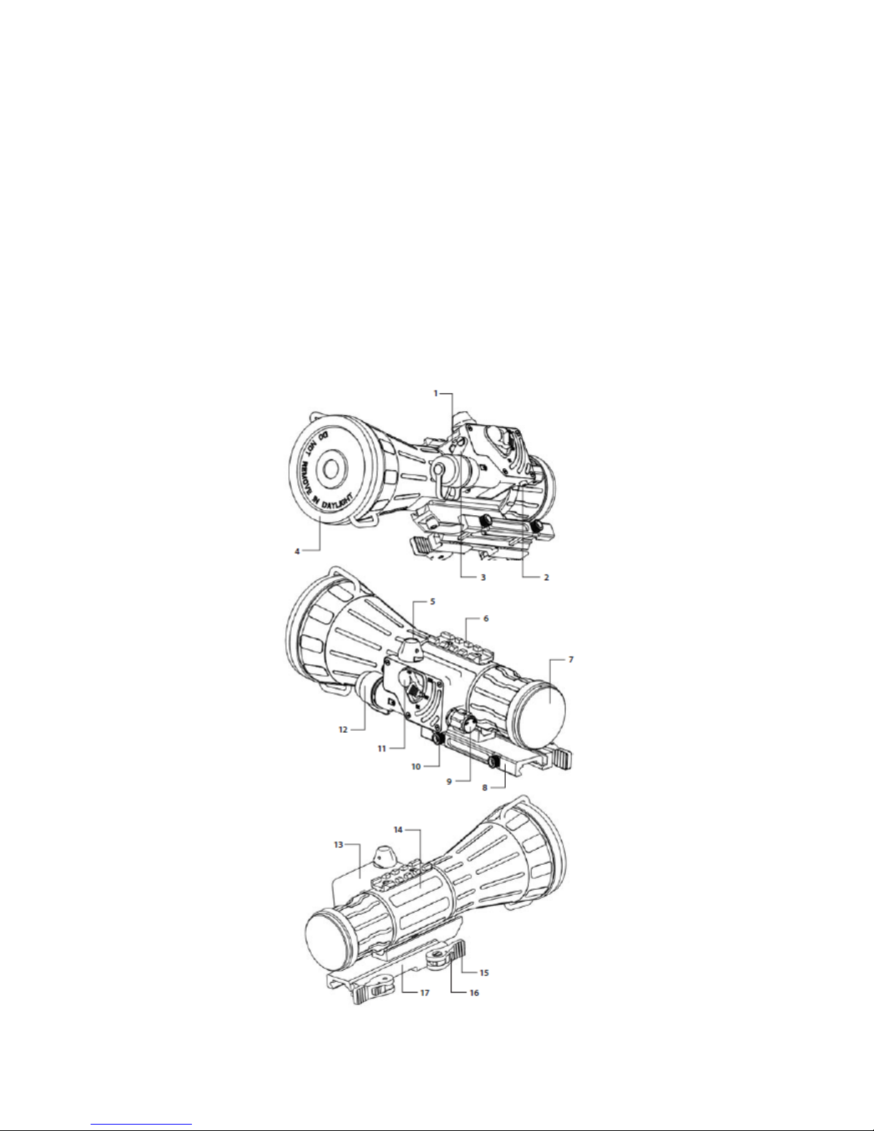
The COT NM-108 BC night vision odule is a precision electro-optical instru ent and requires
careful handling. To avoid physical danger or equip ent da age when using the COT NM-108 BC,
follow all WARNINGS, CAUTIONS and NOTES.
Below you will find definitions of the alerts that appear throughout this Manual:
WARNING — Identifies a clear danger to the person operating the equip ent.
CAUTION — Identifies risk of da age to the equip ent.
NOTE — Serves to highlight essential procedures, conditions, state ents, or conveys i portant
instructional data to the user.
WARNINGS:
• When installing the equip ent on a weapon, be sure the weapon is clear and the safety is on
before proceeding.
• It is reco ended that you use an eyecup on the eyepiece of the day scope, allowing for the
eyepiece dia eter and eye relief and having side paddle preferably in order to escape detection.
• The light fro the infrared illu inator is invisible to the unaided eye. However, the light can be
detected by other night vision devices.
CAUTIONS:
• DO NOT dis antle the equip ent.
• Keep the equip ent clean. Protect it fro oisture, dra atic te perature changes, and electric
shocks.
DO NOT drop or hit the equip ent.
• Protect the equip ent fro overexposure to light: DO NOT activate the equip ent in daylight
with the objective lens cap re oved; DO NOT ai the equip ent at bright light sources (a fire,
car headlights, lanterns, street la ps, roo lights, etc.).
• DO NOT force the equip ent controls past their stopping points.
• DO NOT leave the equip ent activated during breaks in operation.
• Verify that the equip ent is off before installing a battery.
• DO NOT store the equip ent with the battery still in it.
• To avoid defor ation or da age, re ove the light suppressor fro the COT NM-108 BC
before placing the equip ent in storage.
• Thoroughly clean and dry each ite before placing the into the storage case.
NOTES:
• Optical axes of the COT NM-108 BC and day scope should align. It is not reco ended for the
distance between the axes to exceed 3 . If the difference in the axis heights of the COT NM-
108 BC and day scope above the weapon rail exceeds 3 , you will need to replace the day
scope ounting rings or onoblock.
• At operating te peratures below -20 °C, alkaline battery life will be severely reduced. Under
said conditions, the use of lithiu battery is reco ended.
• The equip ent requires so e level of a bient light ( oonlight, starlight, etc.) to function
correctly.

• Perfor ance of the device in nightti e conditions depends on the level of a bient light in the
environ ent. Please re e ber the following:
— The level of a bient light is reduced by the presence of clouds, shade, or objects that block
natural light (trees, buildings, etc.).
— The equip ent is less effective when operated in shadows and other darkened areas.
— The equip ent is less effective when operated in rain, fog, sleet, snow, dust or s oke.
— The equip ent will not “see” through dense s oke.
• For the purpose of returning defective co ponents, retain all packaging aterials.
How to Use T is Manual
USAGE
You ust fa iliarize yourself with this entire anual before operating the equip ent. Before
perfor ing any kind of aintenance on your COT NM-108 BC, read the section on aintenance in
its entirety. Follow all WARNINGS, CAUTIONS, and NOTES.
MANUAL OVERVIEW
The Manual contains sections on operating and aintaining the COT NM-108 BC night vision
odule.
Throughout this Manual, COT NM-108 BC will be referred to as the NM-108 BC , “the device”, or
“the equip ent”.
Reference data for the esti ation of a bient illu ination levels can be found in Appendix A.
C apter 1. INTRODUCTION
1.1 General Information
1.1.1 Type of Manual
Operation and Maintenance (including a List of Spare Parts).
1.1.2 Model Number and Equipment Name
COT NM-108 BC
1.1.3 Purpose of Equipment
The COT NM-108 BC is a night vision syste intended for use in conjunction with a dayti e sight,
or riflescope (hereafter referred to as a “day scope”). When ounted on a weapon in front of an exist-
ing day scope, the NM-108 BC adds to the scope’s capabilities a night vision function (up to range of
900 ), without affecting the boresight. Advisable day scope agnification values are 3 to 12X (4 to
10X are opti al).
The NM-108 BC is co patible with ost co ercial and ilitary specification day scopes, and fits
any Picatinny MIL STD 1913 or Weaver rail via the quick release ount.
An optional long-range IR-illu inator enables use of the NM-108 BC in extre ely low light condi-
tions or total darkness. Other additional equip ent, such as an infrared laser, red dot sight, etc., ay

also be installed on the NM-108 BC top Weaver rail.
NOTE:
The NM-108 BC can also be installed in front of the viewfinders of various instru ents to
widen the operational illu ination range.
C apter 2. DESCRIPTION AND DATA
2.1 System Description
The NM-108 BC consists of two pri ary parts, as shown in Figure 2-1: the night vision device
(hereafter referred to as NVD), and the quick release ount syste , or ount. The NM-108 BC is
delivered already asse bled: the ount (B) should be secured to the rail (A) of the NVD (D) with two
screws.
Figure 2-1. NM-108 BC NIGHT VISION CLIP ON SYSTEM
The optical-electronic syste of the NVD includes four ain co ponents: the objective and output
lenses, an i age intensifier tube, and the wired body (C).
The objective lens focuses available light (photons) on the photocathode of the i age intensifier tube
(IIT). The light energy causes electrons to be released fro the cathode. After being a plified, the
electron flow represents an intensified version of the original i age of the scene. The electrons then
strike the IIT phosphor screen, which reacts to the by glow that is visible to the hu an eye. The i -
age is projected by the output lens fro the IIT screen to infinity, and the resulting i age is agnified
when viewed through the day scope. As such, when the NM-108 BC ounted in front of the day
scope, it converts the latter into a night vision sight.
The auto atic brightness adjust ent syste aintains consistent i age brightness, even in changing
light conditions. The anual gain control (optional feature) allows the operator to refine the i age
contrast by co pensating for overly bright or extre ely dark conditions.
The bright light protection syste controls the existing a bient light through a photoreceiver, and
D
B
A
B
C

cuts off the IIT auto atically when the illu ination level exceeds the li it of 100…150 lx within 10
seconds. The NM-108 BC turns back on when re oved fro the excessive light.
The auto atic shut-off function preserves battery life should the NM-108 BC be inadvertently acti-
vated.
The NM-108 BC is powered by a single AA or CR123A battery.
The NM-108 BC uses a LED indicator to show the operator when the bright light protection syste is
activated, or to indicate a low battery.
The Picatinny / Weaver ount (B) has an adjustable lever-ca cla ping device for easy, quick and
reliable ounting and re oval of the NM-108 BC.
The NM-108 BC is shown in Figure 2-2. The ITEM NO. colu n in Table 2-1 indicates the nu ber
used to identify ite s in Figure 2-2.
Figure 2-2. NM-108 BC NIGHT VISION CLIP ON SYSTEM

TABLE 2-1. SYSTEM DESCRIPTION
ITEM DESCRIPTION ITEM DESCRIPTION
1 Photoreceiver 9 Focus Knob
2 Purge Screw 10 Nut
3 Pivoted Shutter 11 Turn Switch
4 Objective Lens Cap 12 Battery Cap with Adapter
5 Gain Control Knob 13 Control Co part ent
6 Top Weaver Rail 14 Main Body
7 Output Lens Cap 15 Ca Lever
8 Double Lever-Lock Quick-Release
Picatinny Mount
16
17
Lever Holder
Cla p
2.2 Specifications
TABLE 2-2. SYSTEM DATA
ITEM DATA
Magnification Unity (1X)
Boresight Characteristics:
—Accuracy
—Retention
—Repeatability
Factory aligned to 0.75 MOA or better
Per anent to within 1.5 MOA or better
Within 0.75 MOA
Syste Resolution subject to I age Intensifier Tube
Resolution:
—45 to 54 lp/
—55 to 64 lp/
—Over 65 lp/
0.23 rad/lp
0.19 rad/lp
0.16 rad/lp
TABLE 2-3. MECHANICAL DATA
ITEM DATA
Di ensions (L×W×H) 235×97×80
Weight (without Mount and Re ote Control) 0.91 kg
Weight of Mount 0.1 kg
Height of the NM-108 BC Axis above Weapon’s
Picatinny / Weaver Rail
40

TABLE 2-4. ELECTRICAL DATA
ITEM DATA
Battery Single AA (1.5V) or CR123A (3V)
Cell Life at 20°C 25 hr (1.5V) / 45 hr CR123A (3V)
Interrupting Ti e* 60 inutes
* — Optional feature. Interrupting Time setting can be changed at the production stage, or the
function can be completely disabled.
TABLE 2-5. OPTICAL DATA
ITEM DATA
Objective Lens Focal Length 108
Objective Lens F/nu ber 1:1.5
Focus Range 10 to infinity
Field of View 9o
Exit Pupil Dia eter 40
TABLE 2-6. ENVIRONMENTAL DATA
ITEM DATA
Operating Te perature -40 to +50 оС
Storage Te perature -50 to +50 оС
Illu ination Required Natural night illu ination (overcast
starlight to oonlight)
I ersion 10 for 30 inutes
MIL-STD-810 Co plies

2.3 Standard Components
The NM-108 BC standard co ponents are shown in Figure 2-3 and listed in Table 2-7.
The ITEM NO. colu n indicates the nu ber used to identify ite s in Figure 2-3.
Figure 2-3. STANDARD COMPONENTS
TABLE 2-7. STANDARD COMPONENTS
ITEM
NO.
DESCRIPTION Q-TY
1NM-108 BC Nig t Vision Clip-On System - a night vision device equipped with
quick release ount, to be installed on a Picatinny/ Weaver rail. Intended for use in
conjunction with a day scope.
1
2Wireless Remote Control Unit – used to operate the NM-108 BC in short-ti e
activation ode. Ensures quick and silent NM-108 BC activation / deactivation.
Delivered with two CR2016 (3V) batteries installed.
1
3Lig t Suppressor - a rubber cup installed on the NM-108 BC output lens to reduce
light scattering.
1
4Operation and Maintenance Manual - provides safety infor ation, equip ent
description, ounting procedures, operating instructions, and preventive
aintenance checks and services (including a List of Spare Parts).
1

5Special Wrenc - an instru ent used for repositioning the adapter in the NM-108
BC battery cap, depending on the battery being installed.
1
6CR123А Battery - a single lithiu battery used to power the NM-108 BC. 1
7Soft Case - used for carrying / storage of the NM-108 BC and its accessories. 1
2.4 Key Features
•Converts your dayti e scope, sight, or binoculars into a night vision ones
•Mounts in front of any day scope with no re-zeroing required
•Available in a variety of high perfor ing Gen 2+ and Gen 3 i age intensifier tube options
•Wireless re ote control
•Both auto atic and anual gain control
•Powered by a single AA or CR123A battery
•Bright light cut-off syste
•Bright light cut-off and low battery indications in the viewing area
•Interrupting ti e 60 inutes (optional feature)
•Filled with dry nitrogen to prevent internal fogging
•Mounts on Picatinny / Weaver rail with a quick release ount
•Mil Standard co pliant
2.5 System Limitations
The NM-108 BC requires so e a bient light ( oonlight, starlight, etc.) to operate. Factors that can
reduce natural night light and negatively affect the efficiency and operation of the NM-108 BC in-
clude: rain, fog, sleet, snow, and s oke; passing cloud cover and objects that produce shadows; and
low-contrast environ ents such as snow-covered territory, sandy deserts, large bodies of water or
grassy hills.
C apter 3. OPERATING INSTRUCTIONS
3.1 Installation and Mounting
CAUTION:
To protect the i age intensifier tube when the device is not in use or when it is being operated
in daylight, keep the protective objective lens cap securely fitted over the lens.
3.1.1 NM-108 BC Battery Installation
NOTE:
At operating te peratures below -20 °C , alkaline battery life will be severely reduced. Under
said conditions, the use of lithiu battery is reco ended.
CAUTION:
Ensure that the device is off before installing a battery.
Install the battery as follows (refer to Figure 3-1):
1. Unscrew the battery cap (E) and check the position of the adapter (D). See Figure 3-2 for the cor-
rect positioning of the threaded adapter, which changes depending on the battery being installed.
2. If necessary, change the adapter position in the cap. Use the special wrench.

3. Install the battery (C) into the battery co part ent (B). Follow the battery sy bol (A).
4. Replace the battery cap (E).
Figure 3-1. THE NM-108 BC. BATTERY INSTALLATION
Figure 3-2. POSITIONS OF THE ADAPTER IN THE BATTERY CAP
3.1.2 Installing t e NM-108 BC on a Picatinny / Weaver Rail
WARNING:
When installing the equip ent on a weapon, be sure the weapon is clear and the safety is on be-
fore proceeding.
WARNING:
It is reco ended that you use an eyecup on the eyepiece of the day scope, allowing for the
eyepiece dia eter and eye relief and having side paddle preferably in order to escape detection.

NOTE:
Optical axes of the NM-108 BC and day scope should align. It is not reco ended for the dis-
tance between the axes to exceed 3 . If the difference in the axis heights of the NM-108 BC
and day scope above the weapon rail exceeds 3 , you will need to replace the day scope
ounting rings or onoblock.
The NM-108 BC on Picatinny rail in front of a day scope is shown in Figure 3-3.
Install the NM-108 BC on a Picatinny / Weaver rail in front of a day scope as follows:
1. Re ove the output lens cap and place it in the storage case.
2. Re ove the light suppressor fro the storage case. Put it on the output lens in place of the cap.
3. Unlock the cla ping device of the NM-108 BC ount by pushing down on the dogs (A, see Fig-
ure 3-4) and unlocking the levers (B).
4. Install the NM-108 BC on the Picatinny / Weaver rail in front of the day scope so that the stops
(A, Figure 3-5) slide into the transverse slots on the rail. The light suppressor should cover the day
scope’s objective lens.
5. Affix the NM-108 BC to the rail by locking the levers (B, Figure 3-4).
6. Verify that the cla ping device is fir ly holding the NM-108 BC. If necessary, adjust the cla p-
ing device’s lever-ca locks as detailed in Part 3.1.4 (Cla ping Device Adjust ent).
Figure 3-3. THE NM-108 BC INSTALLED ON A PICATINNY RAIL IN FRONT OF A DAY SCOPE
Figure 3-4. MOUNT. TOP VIEW

Figure 3-5. MOUNT. UNDERSIDE VIEW
3.1.3 Clamping Device Adjustment
Adjust the ount cla ping device as follows (refer to Figure 3-6):
1. Re ove the NM-108 BC fro the weapon.
2. With the cla ping device unlocked (as shown in Figure 3-6), push the ca (B) towards the arrow,
which will cause the nut (A) to slide out of its hollow.
3. To tighten / loosen the cla ping device, push down on the ca (B) and turn the nut (A) CW/ CCW
respectively, in one-two incre ents (see note below). Much like when the ca (B) is released, back-
ward- oving springs will cause the nut (A) to slide back into its hollow.
NOTE:
The eight-sided nuts of the ount lever-ca locks will only fit into their hollows only if
turned in one of the discrete positions using incre ents equal to 360o/8.
4. Verify that the adjusted lever-ca lock is fir ly holding the NM-108 BC.
5. Repeat the procedure to adjust the cla ping device’s second lever-ca lock.
Figure 3-6. CLAMPING DEVICE ADJUSTMENT

3.1.4 Fastening Remote Control Unit to Weapon
Using Velcro tape (A), fasten the wireless re ote control unit (B) (Figure 3-7) to a weapon in an eas -
ily accessible place (e.g., on the front of the rifle stock) on the side of the NM-108 BC’s control co -
part ent preferably.
If the rifle has a Picatinny or Weaver rail on the forend you can use the Picatinny adapter for the wire-
less re ote (C). Install adapter on the rail. Insert the wireless re ote control unit in the adapter.
Figure 3-7. REMOTE CONTROL UNIT
3.2 Controls and Indicators
CAUTION:
DO NOT force the equip ent controls past their stopping points.
3.2.1 NM-108 BC Controls and Indicators
The NM-108 BC controls are shown in Figure 3-8.
The MN-108 BC controls and indicators are defined in Table 3-1. The ITEM NO. colu n indicates
the nu ber used to identify ite s in Figure 3-8.
The NM-108 BC controls described elsewhere in this anual (levers and nuts of cla ping device) are
o itted in this Part.

Figure 3-8. NM-108 BC CONTROLS
TABLE 3-1. NM-108 BC CONTROLS AND INDICATORS
ITEM
NO.
CONTROL /
INDICATOR
FUNCTION
1 Pivoted Shutter Closes / opens the photoreceiver when placed in the highest / lowest
position.
2 Gain Control Knob Adjusts the brightness of the i age.
3 Turn Switch Switches on the NM-108 BC, when turned CW fro OFF to ON
position.
NOTE:
Both ON and STB positions can only be entered if the switch is
unlocked by pushing the spring-loaded stop (5) before turning.
Switches the device to standby ode, when turned CCW fro OFF to
STB (see note above).
Switches off the NM-108 BC, when turned CCW/ CW fro ON/ STB
to OFF.
4 Focus Knob Focuses the objective lens. Adjusts for sharpest view of the scene. The
total focus range is covered with 1.5 turn of the knob. Directions of
focus (sharper to softer) are designated by a double arrow on the knob.
5 Spring-loaded Stop
- Re ote Control
Button
- Built-in LED
Indicator
Locks the turn switch in OFF position.
Activates/ deactivates the NM-108 BC in standby when pressed /
released.
PERMANENT RED GLOW in viewing area indicates excessive light
conditions. After 10 seconds the i age intensifier tube will be cut off.
The NM-108 BC turns back again when oved away fro the
excessive light.
FLASHING RED LIGHT in viewing area indicates a low battery. LED
flashes three ti es every 3 inutes.

3.3 Operating Procedures
3.3.1 Operating NM-108 BC
Operating procedures should be perfor ed in night light conditions only.
CAUTION:
USE OF THE CO-LR IN BRIGHTLY LIT CONDITIONS MAY DAMAGE THE IMAGE
INTENSIFIER TUBE.
CAUTION:
PAY ATTENTION TO THE CAUTION NOTICE ON THE OBJECTIVE LENS CAP: “DO
NOT REMOVE IN DAYLIGHT”.
1. Verify that the battery is installed as required.
2. Perfor a visual esti ation of the illu ination level in the viewing area, using the reference data
presented in Appendix A. You can begin operating the NM-108 BC if the illu ination level is less
than 1 lx.
3. Re ove the objective lens cap and place it over the lens’ housing.
CAUTION:
BEFORE REMOVING THE OBJECTIVE LENS CAP, VERIFY THAT THE
PHOTORECEIVER IS OPEN.
4. Verify that there are no bright light sources in the NM-108 BC field of view. Turn the device on.
After a slight delay, a green glow will appear in the day scope’s output lens.
CAUTION:
AVOID EXPOSING THE DEVICE TO BRIGHT LIGHT SOURCES SUCH AS FIRELIGHT,
HEADLIGHTS, SEARCHLIGHTS, ETC., AS THESE CAN DAMAGE THE NM-108 BC.
5. To operate the NM-108 BC in short-ti e activation ode, turn the device on standby. To activate
the NM-108 BC, press and hold the re ote control button. Release the re ote control button to
deactivate the NM-108 BC.
6. Observe the scene. Adjust the focus by rotating the NM-108 BC focus knob until the i age
beco es clear and sharp.
7. Adjust the i age contrast by rotating the NM-108 BC gain control knob.
8. If the day scope includes a focusing ring (i.e., parallax adjust ent knob), adjust the focus for a
parallax free i age.
9. Turn on the day scope’s reticle illu ination and adjust the reticle brightness.
CAUTION:
DO NOT LEAVE THE NM-108 BC ACTIVATED IF IT IS NOT BEING USED.
NOTE:
AUTOMATIC INTERRUPTING TIME IS 60 MINUTES. TO RESUME OPERATION, YOU
WILL NEED TO RESTART THE NM-108 BC.

3.3.2 Operating in C anging Lig t Conditions
If a ission ust be carried out in changing light conditions, you can deactivate the bright light
protection syste of the NM-108 BC. To shut down the protection syste , close the photoreceiver by
flipping up the pivoted shutter.
CAUTION:
AFTER YOUR MISSION IS COMPLETE, OPEN THE PHOTORECEIVER BY FLIPPING
THE PIVOTED SHUTTER DOWN.
3.3.3 S ut-Down
Shut-down the NM-108 BC as follows:
1. Turn the device OFF. The green glow will disappear.
2. Place the cap over the objective lens.
3. Re ove the NM-108 BC fro the weapon.
4. Re ove the light suppressor fro the output lens.
5. Replace the cap on the output lens.
6. Re ove the batteries.
CAUTION:
DO NOT STORE THE EQUIPMENT WITH THE BATTERY STILL IN IT.
CAUTION:
REMOVE THE LIGHT SUPPRESSOR FROM THE NM-108 BC TO AVOID
DEFORMATION OR DAMAGE.
7. Ensure that the NM-108 BC and any accessories are clean and dry before placing the into
the storage case.
8. Place the NM-108 BC and any accessories into the storage case.
9. Store the NM-108 BCand accessories in the appropriate locations in the case and close the
cover.
C apter 4. PREVENTIVE MAINTENANCE AND TROUBLESHOOTING
4.1 Preventive Maintenance C ecks and Services (PMCS)
Table 4-1: Preventive Maintenance Checks and Services, has been provided so that you can keep your
equip ent operable and in good condition.
Perfor all functional tests in the order listed in Table 4-1.
Operating Procedures are detailed in Chapter 3.
Always observe any CAUTIONS that appear in the table.
Explanation of Table Entries:
SEQ NO. column. Sequence nu bers are for reference and appear in the order required to perfor
checks and services.
LOCATION / ITEM TO CHECK / SERVICE column. Indicates the location and the ite to be
checked or serviced.
PROCEDURE column. Details the checking / servicing procedure.
NOT FULLY MISSION CAPABLE IF… column. Indicates what faults will prevent your
equip ent fro operating successfully.

TABLE 4-1. PREVENTIVE MAINTENANCE CHECKS AND SERVICES
SEQ.
NO.
ITEM TO
CHECK
CHECKING PROCEDURE NOT FULLY
MISSION
CAPABLE IF:
BEFORE OPERATION CHECKS
1 Co pleteness Inventory ite s by co paring the with the data
specified in this anual.
Ite s are issing.
2 Body Inspect for cracks or da age. Scratches and
gouges are OK if operation is not affected. Inspect
for issing parts (purge screw, knobs).
Cracked or da aged.
Purge screw or knob
is issing.
3 Objective Lens
Cap
Inspect for cuts, tears and dirt. Clean as required. Cap is torn or cut.
4 Output Lens Cap Inspect for dirt or O-ring da age. Clean as re-
quired.
Cap is not held up on
the lens housing.
5 Battery Co part-
ent / Cap with
Adapter
Check to ake sure the adapter is present. Check
for corrosion, cap da aged or retainer breaks.
Check O-ring for cuts or da age.
Retainer is broken.
Cap, O-ring or
adapter is da aged or
issing.
6 Switch Check for operation (without battery). Switch is inoperative.
7 Lenses Inspect for cleanliness, scratches, chips or cracks.
Clean as required.
Chipped or cracked.
Scratches hinder vi-
sion through the NM-
108 BC.
8 Photoreceiver Inspect for cleanliness, scratches. Clean as re-
quired.
Photoreceiver is da -
aged.
9 Focus Knob Check to ensure there is free rotation through full
range of travel (1.5 turn).
Knob is inoperative.
10 Re ote Control
Unit
Check for da age.
Check Velcro tape for wear.
Da aged. Unit or
tape is issing.
11 Light Suppressor Inspect for cuts or tears. Check ease of installation
and re oval.
Light suppressor is
torn or cut.
12 Mount Inspect for da age or corrosion, and for issing
parts. Check for proper operation.
Da aged. So e parts
are issing. Cla p-
ing device is inopera-
tive.
OPERATIONAL CHECKS
CAUTION:
The objective lens cap has an optical filter, which allows operational testing of the NM-108 BC
in daylight. Activate the NM-108 BC in daylight with the objective lens cap on or in dark
conditions.
NOTE:
Daylight checks are described below.

CAUTION:
DO NOT forget to open the photoreceiver after finishing operational checks
13 NM-108 BC
Switch
Insert the battery. Re ove the output lens cap.
Close the photoreceiver by flipping up the pivotal
shutter. Turn the switch to ON position. Look for
green glow (after a slight delay) in viewing area.
Open the photoreceiver by flipping the pivotal
shutter down. Look through the output lens and
wait about 10 seconds for green glow to disappear.
No green glow.
Green glow is
present, yellow glow
is absent.
14 Re ote Control Close the photoreceiver. Put the device in STB.
Press and hold the re ote control button. Look for
the green glow in output lens. Release the button.
Turn the device off.
Green glow is absent.
15 Focus Knob Turn the device on. Rotate the knob to ensure it
adjusts for focus.
Knob does not adjust
for focus.
16 Gain Control
Knob
Rotate the gain control knob to ensure it changes
the screen brightness.
Knob does not adjust
the screen brightness.
17 Viewed I age Inspect for any operational defects (refer to Sec-
tion 4.3: Inspection Criteria for Proper I age In-
tensifier Tube Operation).
Shading, edge glow,
flashing, flickering,
and inter ittent
operation, or exces-
sive cos etic defects
are found.
AFTER CHECKING PROCEDURES
18 Turn off the NM-108 BC. Replace the protective cap on the NM-108 BC output lens.
Re ove the batteries. Return the NM-108 BC and all accessories to the storage case.
4.2 Operator Troubles ooting
The purpose of troubleshooting is to identify the ost co only occurring equip ent alfunctions,
their probable causes, and the corrective actions required to fix the .
Table 4-2 lists the co on alfunctions that ay occur during the operation or aintenance of the
NM-108 BC. Perfor the tests, inspections, and corrective actions in the order listed in the table.
T is table cannot list all of t e malfunctions t at may occur wit t e NM-108 BC, or all of t e
tests and corrective actions t at may be necessary. If you experience an equip ent alfunction
that is not listed, or is not fixed by the corrective actions listed in the table, please contact Ar asight’s
Custo er Service center.

TABLE 4-2. OPERATOR TROUBLESSHOOTING
MALFUNCTION PROBABLE CAUSE / TEST/
INSPECTION
CORRECTIVE ACTION
Equip ent fails to activate. Battery is issing or i properly
installed.
Battery is dead.
Battery surfaces or contacts are
dirty or corroded.
Re ote control unit is da aged.
Re ote control batteries are
dead.
Defective i age intensifier tube.
Insert battery or install it cor-
rectly.
Replace battery.
Clean the contact surfaces with a
pencil eraser and / or alcohol and
cotton swabs.
Please contact Custo er Support.
Replace the batteries as per Part
4.4.3.
Please contact Custo er Support.
Poor i age quality. Check focus.
Objective and output lenses are
dirty.
Da aged optical co ponents.
Refocus.
Thoroughly clean the surface of
each lens.
Please contact Custo er Support.
LED indicator fails to activate. Visual inspection. Please contact Custo er Support.
The NM-108 BC affects bore-
sight after installation or dur-
ing the firing.
Factory align ent is broken. Please contact Custo er Support.
Hindered rotation of the bat-
tery cap.
Dirty cap thread.
Da aged cap thread.
Clean the thread.
Please contact Custo er Support.
Battery adapter difficult to re-
ove.
Check for da aged adapter and
battery cap.
If da aged please contact Cus-
to er Support.
Light visible around light sup-
pressor.
Incorrect position of the NM-108
BC relative to the day scope.
Check the light suppressor re-
silience.
Align the NM-108 BC position
relative to the day scope.
If light suppressor is defective
please contact Custo er Support.
4.3 Inspection Criteria for Proper Image Intensifier Tube Operation
4.3.1 Operational Defects
Operational defects relate to the reliability of the intensifier, and are an indication of instability. If
identified, the user will need to return the NM-108 BC i ediately. Operational defects include
shading, edge glow, flashing, flickering, and inter ittent operation.
A. S ading
If shading is persistent, you will not be able to see a fully circular i age (Figure 4-1). Shading is a
very dark, high-contrast area with a distinct line of de arcation present, and you cannot see an i age
through it. Shading always begins on the edge and will eventually igrate inward until it spans across
the entire i age area. If you notice shading with your device, please contact Custo er Support.

Figure 4-1. SHADING
NOTE:
VERIFY THAT ANY SHADING IS NOT THE RESULT OF IMPROPER EYE-RELIEF
ADJUSTMENT.
B. Edge Glow
Edge glow is a bright area (it so eti es appears to be coloring) in the outer portion of the viewing
area (see Figure 4-2). To check for edge glow, block out all light fro the device by cupping a hand
over the lens. If the i age intensifier tube is displaying edge glow, the bright area will still show up; if
edge glow occurs please contact Custo er Support.
Figure 4-2. EDGE GLOW
C. Flas ing, Flickering, or Intermittent Operation
The i age ay appear to flicker or flash. If there is ore than a single flicker, check for a loose bat-
tery adapter or a weak battery. If flickering continues, please contact Custo er Support.
4.3.2 Cosmetic Blemis es
Cos etic ble ishes are usually the result of anufacturing i perfections. They do not affect the
reliability of the i age intensifier tube, and are not nor ally a cause for returning the NM-108 BC.
However, so e types of cos etic ble ishes can worsen over ti e and interfere with the user’s ability
to properly operate the device during issions. If you believe a cos etic ble ish is cause for
returning the device, record the specific nature of the proble on the aintenance for s and use the
clock ethod to identify the position of the ble ish and approxi ate distance fro the center (e.g.,
5:00 toward the outside, 2:30 near the center, or 1:00 idway).
The following are exa ples of cos etic ble ishes:
Table of contents