5 October 2021Page 4 LawnBoss ZTR Model A19120G
PRE-DELIVERY INSTRUCTIONS
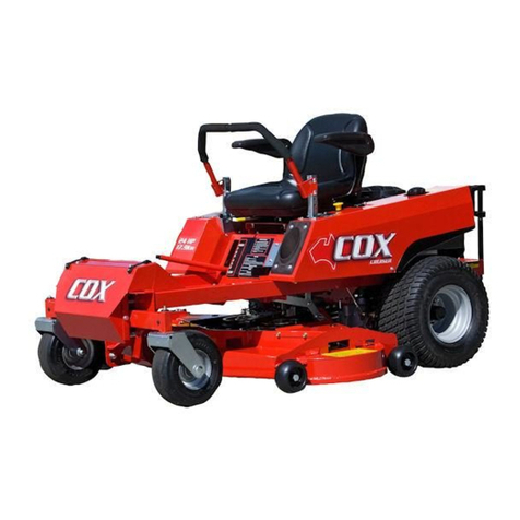
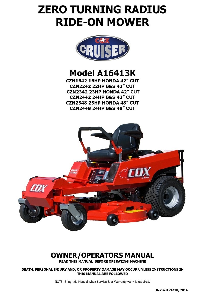
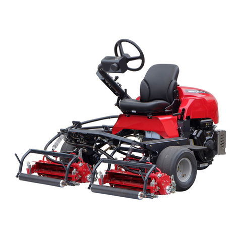
THANK YOU, for purchasing a COX LawnBOSS ZTR
Ride-on Mower.
RESPONSIBILITY:
It is the responsibility of the dealer/distributors to ensure that
before a machine is delivered to a customer, it is in perfect
operational condition.
PROCEDURE:
Unpacking Instructions - Inspect the shipping crate and contents
for damage. Position the shipping crate on a firm flat level surface
with at least 3 meters distance from any obstruction to the end of the
crate adjacent to the front of the Ride-on Mower.
! Caution you can be seriously injured by the metal
strapping which has sharp edges and can spring out when
cut. Wear gloves when handling metal strapping.
! Caution you can be seriously injured by sharp nails
protruding from the shipping crate.
Cut and remove the straps restraining the Ride-on Mower to the
ends of the shipping crate. Remove the end of the shipping crate
adjacent to front of the Ride-on Mower. Remove the plastic sheet
covering the Ride-on Mower.
Unlock the park brake by moving the park brake lever down fully.
Unlock the Transaxle Disengage Link from the engaged position
by lifting up then pulling fully towards the back of the Ride-on
Mower then pushing down to lock in the disengaged position. Pull
the Ride-on Mower from the shipping crate. Once stopped the
Park Brake Lever should be locked on by pulling lever up fully.
Remove the Drive Control Levers. Seat Sub-assembly, & other
loose components from the packaging.
Dispose of all packaging material responsibly.
Do not leave the plastic sheet unrestrained, it can blow
away to become a safety hazard.
CHECK PARTS SUPPLIED IN SEAT PROTECTION BAG
Seat Sub-assembly (A191246)
Pre-delivery Instruction Sheet
Operators Guide Booklet
Engine owner’s manual
Ignition keys (AM015)
Seat Spring x 3 (A163060)
Hex Screw (M8X20) x 3 (SH0820M)
Flat Washer (M8) x 3 (W05M202)
Nyloc Nut (M8) x 3 (NM8NT)
Seat Spring Cap x 3 (A168231)
Cup Head Bolt (M8x40) x 4 (BCHSNM8X40)
Spring Lock Washer (M8) x 4 (WS05021.6)
Dome Nut (M8 ) x 4 (ND08M)
Spring Pull Hook x 1 (13127)
CHECK ITEMS SUPPLIED LOOSE
Left Drive Control Lever (A191117)
Right Drive Control Lever (A191118)
ASSEMBLY: TOOLS & EQUIPMENT REQUIRED:
Socket set containing 13mm a/f socket & extension 75mm (3”) or
longer. Spanner 13mm a/f.
Refer pictorial procedure provided.
INITIALISE HOURMETER (if fitted)
Turn the Hourmeter on by pushing the Button located below the cover
adjacent to the last S of the word PowerBOSS printed on the
Hourmeter until the display of the Hourmeter shows the three digits
0.00. The Hourmeter is of a vibration type and will record (once on)
the number of hours the engine vibrations excites the Hourmeter.
Once on the Hourmeter will continuously display the operating hours.
INSTALL SEAT SPRINGS & MOUNT SEAT
Install the three seat springs using the screws, washers, nuts, to
the Rear of the Centre Console, and tighten the screws, washers,
and nuts. Install the Seat & Mounting to the Front of the Centre
Console using the Screws Washers and Nuts. Attach seat switch
wiring to seat switch.
INSTALL DRIVE CONTROL LEVERS -
Install the Left & Right Drive Control Levers using the Bolts,
Washers, & Dome Nuts, to the sides of the Neutral Links
at a height position to suit the operator.
Align the Grips on the Drive Control Levers and tighten at a
backwards/forwards position to suit the operator.
ADJUST SEAT POSITION & FLOOR/FOOTREST POSITION
Adjust the Seat position to suit the operator if required.
Adjust the Floor/Footrest position to suit the operator if required.
CHECK TYRE PRESSURE
Before operation ensure that all tyre pressures are equal from side
to side. The recommended pressures are:-
Front Wheel:-140 Kpa (20psi) approximately.
Rear Wheel:- 105 Kpa (15psi) 18x6.50-8 & 18x8.50-8
BATTERY
This machine is fitted with a maintenance free battery.
Recharge only if required.
ENGINE OIL
Before operation ensure that engine oil level is to the full mark on
the dipstick. (Read engine owners manual for correct procedure
to check & adjust oil level).
FUEL TAP
Ensure the fuel taps at the bottom inside of the Right Side Fuel
Tank is turned to the on position before attempting to start
engine. (Use unleaded fuel only). Turn Fuel Tap off after use.
CHECK OPERATION OF SAFETY START SWITCHES
Drive Lever Switches - With Cutter PTO switch in DISENGAGED
position and Park Brake Lever set in the ON position and the Drive
Control Levers in the DRIVE position. Attempt to start the engine.
Engine should not start.
Cutter PTO Switch - With Drive Control Levers in the locked out
NEUTRAL position and Park Brake Lever set in the ON position,
and Cutter PTO Switch in the ENGAGED position. Attempt to start
engine. Engine should not start.
Park Brake Lever Switch -
With Cutter PTO Switch in DISENGAGED position and the Drive
Control Levers set in the locked out NEURAL position, and the
Park Brake Lever in the OFF position. Attempt to start the engine.
Engine should not start.
With Cutter PTO Switch in DISENGAGED position and the Drive
Control Levers in the locked out NEUTRAL position and the Park
Brake Lever set in the ON position. Attempt to start the Engine.
Engine should start.
Seat Switch -
While sitting on stationary machine with Engine running ENGAGE
Cutter PTO Switch. Lift weight from Seat. Engine should stop.
While sitting on stationary machine with Engine running and
Cutter PTO Switch in DISENGAGED position, set the Park Brake
Lever in the OFF position and then the Drive Control Levers in the
DRIVE position. Lift weight from Seat. Engine should stop.
Drive Control Lever Switches -
While sitting on stationary machine with Engine running
and Cutter PTO Switch in DISENGAGED position and Park
Brake Lever set in the ON position attempt to move the
Drive Control Levers to the DRIVE position. Engine should
stop.
Park Brake Lever Switches -
While sitting on stationary machine with Engine running
and Cutter PTO Switch in DISENGAGED position, and Drive
Control Levers in DRIVE position, attempt to set the Park
Brake Lever in the ON position.
Engine should stop.


