manuals.online logo
Brands
  1. Home
  2. •
  3. Brands
  4. •
  5. COX
  6. •
  7. Lawn Mower
  8. •
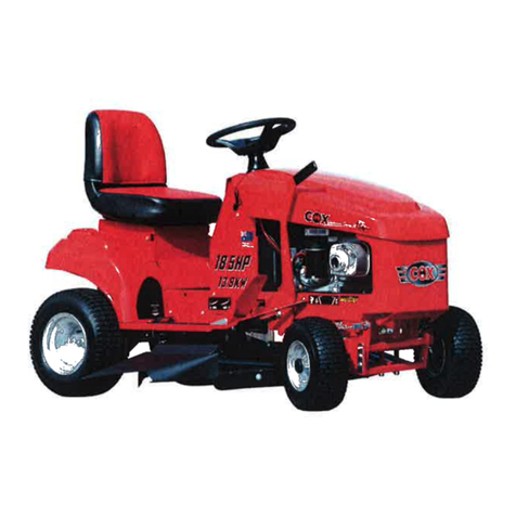
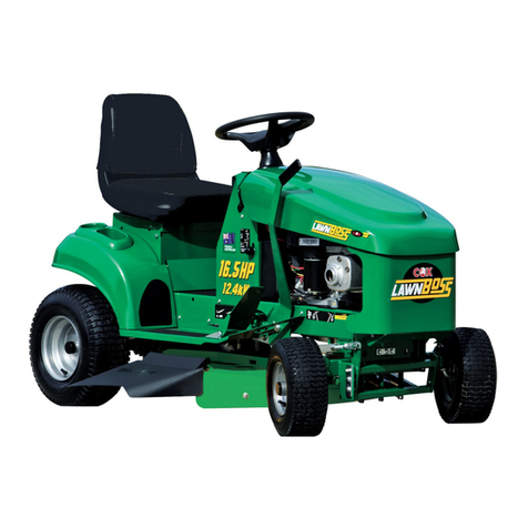
  9. COX Greenfield Fastcut 2 User manual

COX Greenfield Fastcut 2 User manual

Model A20318L
Product GFC24P32
V-Twin 24/32 Steel Deck
Model A20318L
Product GFD24P35
V-Twin24/35 Steel Deck
Model A20318L
Product GFD23V35
V-Twin Vanguard 23/35 Steel Deck
Model A20318L
Product GFC17B32
17/32 Steel Deck
Model A20318L
Product GFD17B35
17/35 Steel Deck
READ THIS MANUAL BEFORE OPERATING MACHINE
DEATH, PERSONAL INJURY AND/OR PROPERTY DAMAGE MAY OCCUR UNLESS INSTRUCTIONS IN
THIS MANUAL ARE FOLLOWED
NOTE: Bring this Manual when Service & or Warranty work is required.
REGISTER YOUR WARRANTY ONLINE
http://www.coxmowers.com.au/warranty-registration/
Owners Manual
Page 2December 2018
OWNERS MANUAL FOR MODEL A20318L
TABLE OF CONTENTS
Owner Information Page 3
Safety Instructions Page 4-5
Introduction - General Instructions - Unpacking & Pre-delivery Page 6-9
Operating Instructions Page 10-11
Maintenance Instructions & Schedule Page 12-18
Warranty Page 19
Illustrated Parts Lists
Body Components Classic Page 20-21
Body Components Deluxe Page 22-23
Bonnet Components (No Lights) Page 24-25
Bonnet Components (With Lights) Page 26-27
Seat Assembly Components Page 28-29
Seat Mount Sub-Assy & Seat Springs Page 30-31
Console Body & Components Page 32-33
Upper Steering Page 34-35
Lower Steering & Front Axle Components Page 36-37
Front & Rear Wheels Page 28-39
Wiring Diagram 17.5HP B&S Page 40-41
Wiring Diagram 24.0HP PBS Page 42-43
Electrical Components Page 44-45
Engine Auxillary Components Page 46-51
Drive Control Page 52-55
Transmission Page 56-57
Drive Clutch Components Page 58-59
Drive Yoke Components Page 60-61
Transmission Drive Page 62-65
Drive Chain & Park Brake Page 66-67
Rear Axle, Brake & Chain Tensioner Page 68-73
Differential Components Page 74-75
Mowing Attachment Suspension Page 76-83
32” Mowing Attachment Page 84-87
35” Mowing Attachment Page 88-89
Page 3December 2018
OWNERS MANUAL FOR MODEL A20318L
OWNERS INFORMATION
MODEL NO: _________________________________
PRODUCT CODE NO: ________________________
SERIAL NO: _______________________
Located on Label inside Console
ENGINE NOS: _____________________________________________________________________________
(As applicable) Located on Engine refer Engine Owners Manual
DATE OF PURCHASE: _________________________________
OWNERS NAME:
ADDRESS:
TOWN/CITY:
STATE:
AUTHORISED
DEALER/DISTRIBUTOR:
ADDRESS:
TOWN/CITY:
STATE:
PRE DELIVERY CHECK LIST
Check parts Assemble Service Instruction 
ALWAYS KEEP THIS MANUAL IN A SAFE PLACE.
Page 4December 2018
OWNERS MANUAL FOR MODEL A20318L
Page 5December 2018
OWNERS MANUAL FOR MODEL A20318L
 Read, understand, & follow all instructions in the Owner/
Operators manual.
 Know the controls and how to stop the engine quickly in an
emergency.
 Allow only responsible adults, who are familiar with the
instructions in this manual, to operate the machine.
 Clear the area to be mowed of loose objects such as
sticks, stones, bones, wire, toys, debris, etc., which could
be picked up and thrown by the blades.
 DO NOT mow whilst people, especially children, or pets
are in the mowing area.
 DO NOT mow either direction on slopes beyond 15
degrees, (1 in 3.75), (27%).
 Exercise extreme caution on slopes.
 Reduce speed on slopes and in sharp turns to prevent
overturning or loss of control.
 Start or stop slowly when on slopes.
 Mow up and down slopes, not across the slope.
 Stay alert for holes or bumps in the terrain and other
hidden hazards.
 Use care when pulling loads-
a] Use only approved hitch point;
b] limit loads to those you can safely control;
c] Do not turn sharply;
d] use care when backing up.
 Watch out for traffic when crossing or operating the mower
near roadways.
 Stop the blades rotating before crossing surfaces other
than grass.
 When using attachments, never direct discharge of
material toward bystanders nor allow anyone near the
machine while it is in operation.
 Before leaving the operators position-
a] Disengage all clutches and secure cutting units;
b] Return drive pedal to neutral position and set the parking
brake;
c] Stop the engine and remove the key.
 Disengage drive to attachments and stop engine-
a] Before refueling.
b] Before removing grass-catcher;
c] Before clearing blockages from chute;
d] Before checking, cleaning or working on the mower;
e] After striking a foreign object (check the mower for
damage and make repairs before restarting and operating
the equipment);
f] If machine starts to vibrate abnormally (check
immediately).
 Disengage drive to attachments when transporting or not in
use.
 A mower operator should be in good physical and mental
health and not under the influence of alcohol or any drug
which might impair vision, co-ordination or judgment.
 Never mow while barefoot or wearing open sandals or
thongs. Wear long trousers and heavy shoes.
 It is advisable to wear suitable eye protection when
operating a mower.
 Mow only in daylight or good artificial light.
 Before using, always visually inspect to see that blades,
bolts and cutter assembly are not worn or damaged.
Replace worn or damaged blades and bolts in sets to
preserve balance.
 Check all nuts, bolts, and screws often; always be sure the
mower is in safe operating condition.
 Keep safety devices (guards and switches) in place and in
working order.
 Never use the mower unless the grass catcher, or guards
provided by the manufacturer, are in position.
 Ensure any replacement parts used comply with the
original manufacture’s recommendations and
specifications.
 Replace worn or faulty silencers.
 Keep machine free of grass, leaves or other debris,
excessive oil, grease, or spilt fuel. These can be a fire
hazard.
 Refuel outdoors only. Do not smoke while fueling engine.
Never remove the cap of the fuel tank or add petrol while
the engine is running or the engine is hot. Remove fuel cap
slowly to relieve any tank pressure. If fuel is spilled, do not
attempt to start the engine but move machine away from
the area of the spill and avoid creating any source of
ignition until fuel vapors have dissipated.
 Check for fuel leaks while refueling, before and while using
the mower. If a fuel leak is found, do not start or run the
engine until the fuel leak is fixed and spilled fuel is wiped
away.
 Do not operate engine in a confined space where exhaust
fumes (carbon monoxide) can collect.
 Always mount the mower from the opposite side to the
cutter housing discharge chute.
 Start the engine carefully with the cutting means
disengaged.
 Do not over-speed the engine or alter governor settings.
Excessive speed is dangerous and shortens mower life.
 Stop the engine whenever you leave the mower, even for a
moment.
 Store the mower in a well-ventilated room away from naked
flames such as may be found in hot water heaters.
 Do not lend or sell the mower, without the owners/
operators Manual.
SAFETY INSTRUCTIONS
Page 6December 2018
OWNERS MANUAL FOR MODEL A20318L
INTRODUCTION
THANK YOU, for purchasing a FastCUT 2 Ride-on Mower.
Please follow the manufacturer’s safety, operating and maintenance instructions for many year of trouble free
operation and service.
Proudly Manufactured by Cox Industries (Australia) Pty. Ltd..
GENERAL SAFETY INSTRUCTIONS
READ THIS MANUAL carefully to learn
how to operate safely and maintain your
Ride-on Mower effectively.
Failure to follow Safety, Operating or
Maintenance instructions in this manual
could result in
Death, Personal Injury or Equipment
Damage.
THIS MANUAL IS PART OF YOUR
RIDE-ON MOWER and should be
supplied with this Ride-on Mower if you
lend or sell this Ride-on Mower. This
should also apply to the Engine Owners
Manual.
CONVENTIONS
Measurements in this manual are given
in metric units unless otherwise stated.
Right-hand and Left- hand, are
determined by facing the direction of
forward travel.
Direction of rotation is determined by
looking into the components in motion
parallel to the axis of rotation.
WRITE PRODUCT IDENTIFICATION
NUMBERS in the Owners Information
Section of this manual. Accurately
recording these numbers will assist your
Dealer when ordering spare parts or
help in tracing the Ride-on Mower if it
should be stolen. Store this manual in a
secure place remote from the Ride-on
Mower.
ENSURE YOU UNDERSTAND THE
WARRANTY POLICY with regard to the
r e s p o n s i b i l i t i e s o f o p e r a t i o n ,
maintenance and ownership of this
FastCUT 2 Ride-on Mower.
THE INTENDED USE OF THIS RIDE-
ON MOWER is for customary mowing of
Landscaped Parks, Gardens, Grounds,
Sporting Fields, Road Verges, Golf
Course Fairways, Orchards, Plantations,
and Vineyards.
Strict adherence to the conditions of
Operation, Maintenance, Service &
Repair as specified by the manufacturer
constitute essential elements for The
Intended Use.
Use in any other way not specifically
approved directly in writing by the
manufacturer is considered as contrary
to the intended use and will increase the
risk of personal injury or property
damage and is therefore considered as
misuse for which the manufacturer
accepts no responsibility as these
increased risks must be accepted solely
by the user.
Do Not Modify the Machine without
direct specific approval by the
manufacturer as modification is
considered contrary to the intended use
and will increase the risk of personal
injury or property damage and is
therefore considered as misuse for
which the manufacturer accepts no
responsibility as these increased risks
must be accepted solely by the user.
O P E R AT I O N , M A I N T E N A N C E,
SERVICE AND REPAIR of this Ride-on
Mower should be performed only by
persons familiar with its characteristics
and acquainted with the relevant Safety,
Operating and maintenance instructions
in this manual, as well as all relevant
Statutory Regulations in force at the
place and time.
When your Ride-on Mower needs
service or repair please remember your
Dealer is an industry trained
professional who is supported by the
personnel of the Sales and Marketing,
Engineering, Production, Procurement,
Parts Distribution, & Service Sections of
the Manufacturer and is dedicated to
your satisfaction.
THE INFORMATION INCLUDED IN
THIS MANUAL was considered correct
at the time of approval for printing. Cox
Industries (Australia) Pty Ltd reserves
the right to change specifications or
designs without notice or obligation.
Training
Read, understand and follow all
instructions in the Ride-on Mower and
Engine Owner’s/Operator’s Manual as well
as on Machine Safety Signs.
Keep up to date with and follow all
relevant statuary regulations in force at the
place and time with regard to ownership,
transport, operation, maintenance, service,
and repair, disposal or sale of this machine.
Know the controls and the proper
use of the Equipment as well as how
to stop the Mowing Attachment,
Machine Travel, and the Engine in an
emergency.
All operators or users should seek
and obtain professional and practical
instruction.
Such instruction should emphasize:
The need for concentration when
working with ride-on machines.
Control of a ride-on machine sliding on
a slope will not be regained by
application of the brake.
The main reasons for loss of control are:
i) Insufficient wheel grip;
ii) Being driven to fast;
iii) Inadequate braking;
iv) The type of machine is unsuitable
for the task;
v) Lack of awareness of the effect of
ground conditions, especially
slopes;
vi) Incorrect hitching and load
distribution.
Never allow children or people
unfamiliar with these instructions to
operate the Ride-on Mower.
Never carry passengers.
Never mow while people, especially
children, or unrestrained animals are
nearby.
Keep in mind that the operator or user
is responsible for accidents or hazards
occurring to other people or their
property caused by this machine.
Page 7December 2018
OWNERS MANUAL FOR MODEL A20318L
Preparation
While operating, always wear
substantial footwear (not open sandals)
and long trousers.
Thoroughly inspect the area where
the equipment is to be used and
remove all objects which can be thrown
by the machine.
WARNING –Petrol is highly
flammable:
i) Store fuel in containers specifically
designed for this purpose;
ii) Refuel outdoors only;
iii) Do not smoke while refuelling;
iv) Add fuel before starting the engine;
v) Never remove the cap of the fuel
tank or add petrol while the engine
is running or when the engine is
hot;
vi) If petrol is spilled, do not attempt to
start the engine but move the
machine away from the area of
spillage and avoid creating any
source of ignition until petrol
vapours have dissipated;
vii) Replace all fuel tank caps and
container caps securely.
Replace faulty Mufflers.
Before using, always visually inspect
to see that the cutter assembly, blades,
and blade bolts are not worn or
damaged.
Replace worn or damaged blades
and bolts in sets to preserve balance.
Take care rotating one blade by hand
as this can cause other blades to rotate.
Operation
Do not operate the engine in a
confined space where dangerous
carbon monoxide fumes can collect.
Operate the machine only in daylight
or in good artificial light.
Before attempting to start the
engine, disengage the power take off
switch and depress heel switch.
There is no such thing as a safe
slope.
Do not use on slopes of more than
15 degrees (1 in 3.75 or 27%).
Travel on grass slopes requires
particular care.
To guard against overturning:
i) Do not stop or start suddenly when
going up or downhill;
ii) Apply reverse drive gently to
control speed, when travelling
downhill;
iii) Machine speeds should be kept
low on slopes and during tight
turns;
iv) Stay alert for humps and hollows
and other hidden hazards;
v) Never mow across the face of
the slope.
Use care when pulling loads or using
heavy equipment:
i) Use only approved hitch points;
ii) Limit loads to those you can safely
control;
iii) Do not turn sharply;
iv) Use care when reversing;
Watch out for traffic when crossing or
near roadways.
Stop the blades rotating before
crossing surfaces other than grass.
When using the mowing attachment,
never direct discharge of material
towards bystanders nor allow anyone
else near the machine while it is
operating.
Never operate the machine with
defective guards, or without all safety
devices in place and operating
correctly.
Do not change the engine governor
settings or over speed the engine as
excessive engine speed can increase
the risk of personal injury.
Before leaving the operators
position:
i) Disengage the power take off clutch:
ii) Set the parking brake in the locked
position.
Disengage drive to attachments
when transporting, emptying the
catcher, or not in use.
Disengage drive to attachments and
stop engine before refuelling.
Disengage drive to attachments,
stop engine, and remove the ignition
key:
i) Before leaving the machine
unattended;
ii) Before clearing blockages or
unclogging the chute;
iii) After striking a foreign object.
(Inspect the machine for damage
and make repairs before restarting
or operating the damaged
equipment);
iv) If the machine starts to vibrate
abnormally. (Check immediately).
Disengage drive to attachments,
stop engine, remove the ignition key,
and disconnect the spark plug wires
and battery positive lead before
working on, maintaining, or servicing
the machine.
Secure the mowing attachment in the
full up position:
i) Before clearing blockages or
unclogging the chute;
ii) Before replacing the blades, or
adjusting the tension o f t h e
blade bolts;
iii) Before placing any tools or any
part of your person under the
mowing attachment.
Turn the fuel off using the fuel shut
off valve at the conclusion of operation.
Maintenance and
Storage
Keep all nuts, bolts and screws tight
to ensure the equipment is in safe
working order.
Replace worn or damaged parts for
safety.
Reduce the fire hazard, by keeping
the engine, muffler, drive system,
battery compartment, and petrol
storage area clear of grass, leaves, or
excessive oil and grease.
Also ensure the mowing attachment
drive belt can not come into contact
with grass, sticks, and leaves built up
on the top surface of the mowing
attachment.
If the fuel tank has to be drained this
should be done outdoors.
Never store the machine with petrol
in the tank inside a building where
fumes can reach an open flame or
spark.
Allow the engine to cool before
storing the Ride-on Mower in any
enclosure.
When the machine is to be parked,
stored or left unattended raise the
mowing attachment and secure it in the
full up position.
Page 8December 2018
OWNERS MANUAL FOR MODEL A20318L
PRE-DELIVERY INSTRUCTIONS
Unpacking Instructions
Inspect the shipping crate and contents for
damage.
Position the shipping crate on a firm flat level
surface with at least 3 meters distance from any
obstruction to the end of the crate adjacent to
the front of the tractor.
! Caution you can be seriously injured
by the metal strapping which has sharp
edges and can spring out when cut.
Wear gloves when handling metal
strapping.
! Caution you can be seriously injured
by sharp nails protruding from the
shipping crate.
Cut and remove the straps restraining the
tractor to the ends of the shipping crate.
Remove the end of the shipping crate adjacent
to front of the tractor.
Remove the plastic sheet covering the tractor.
Unlock the park brake by lowering the knob to
the off position.
Pull the tractor from the shipping crate. Depress
the brake pedal to stop travel. Once stopped
the park brake should be locked on by raising
the knob to the on position.
Remove the steering wheel, seat sub-assy, &
other loose components from the packaging.
Dispose of all packaging material
responsibly.
Do not leave the plastic sheet unrestrained,
it can blow away to become a safety hazard.
UNPACKING INSTRUCTIONS
INTRODUCTION:
The purpose of this procedure is to ensure
the dealer/distributor has assembled & made
the necessary checks, & adjustments, before
the mower is operational, and instructed the
owner in its safe operation & maintenance.
This procedure begins upon receiving the
crated mower and is finalised once the
mower has been either sold or leaves the
dealer/distributors premises. This is the
minimum amount of work required, however
it should not be limited to only the areas
detailed in this procedure.
RESPONSIBILITY:
It is the responsibility of the dealer/
distributors to ensure that before a mower is
delivered to a customer, it is in perfect
operational condition.
PROCEDURE:
UNCRATE THE MOWER
CHECK COMPONENTS SUPPLIED IN
SEAT PROTECTION BAG
Engine owners manual
 Owner/Operator manual
Ignition keys (AM015)
Washer,Lock,Spring (WS050216) x 1
Set Screws M8X20 (SH0820M) x 3
Nuts M8 Nyloc (NM8NT) x 2
Seat Springs x 2 (A163060)
Spring Caps x 2 (A160231)
Washer (W05M202) x 2
Cap, Str Inc Badge (A203298) x 1
Seat Washer (WSEAT08X27X3) x 1
 Screw, Cap M5X25 x 6
Pre-delivery Instruction Sheet
ASSEMBLY:
TOOLS & EQUIPMENT REQUIRED:
Socket set containing 13mm a/f socket &
extension 75mm (3”) or longer. Spanner 13mm
a/f., 1/2” a/f hex key. Refer pictorial procedure
provided.
STEERING WHEEL
To attach the steering wheel, insert the
wheel onto the steering shaft ensuring the
flats machined on the shaft engage with the
ones in the steering wheel. Secure the wheel
to the shaft with 5/16 UNC bolt and spring
lock washer included with the machines tool
kit. Lastly secure the centre badge and bezel
with the 6 cap screws included with the
machines tool kit.
HOURMETER
The PowerBOSS hourmeter included with the
machine has an internal battery designed to last
for the warranty period of the machine. It does
not need to have power connected to it. Your
dealers will program the hourmeter with service
reminders as per the servicing periods outlined
in this manual.
SEAT MOUNT & SEAT SPRINGS
Install the two seat springs using the screws,
washers, nuts, to the seat slide frame, and
tighten the screws, washers, and nuts.
Install the Seat & Mounting to the seat slide
frame using the Screws and Nuts. Attach
seat switch wiring to seat switch.
CHECK TYRE PRESSURES & FLUID
LEVELS:
TYRES
Before operation ensure that tyre pressures
are equal on both sides. Uneven pressure
can give an uneven finish when mowing and
may cause damage to tyres and/or tubes.
The recommended pressure is:
Front 170kPa (24 P.S.I.). Rear 140kPa (20 P.S.I.)
BATTERY
This machine is fitted with a maintenance free
battery. Ensure battery indicator is green.
ENGINE OIL
Before operation ensure that engine oil level
is to the full mark on the dipstick. (Refer
engine owners manual for procedure & if oil
needs to be added refer Engine Owners
Manual for Correct Grade).
FUEL
Ensure there is fuel above the fuel tap & the
fuel tap at the bottom left front side of fuel
tank is turned to the on position before
attempting to start engine. (Use unleaded
fuel only).
Turn off fuel tap after use.
CHECK OPERATION OF SAFETY
SWITCHES:
STARTING
Foot Switch - With the PTO (power take
off) switch in disengaged position (off),
attempt to start the engine without
depressing the foot switch.
Engine should not start.
PTO Switch - While sitting on seat with
foot on foot switch and PTO switch in up
(engaged) position, attempt to start the
engine.
Engine should not start.
Key Switch
With PTO switch in down (disengaged/off)
position & foot switch depressed turn key
switch to start position.
Engine should start.
STOPPING
Seat Switch - While sitting on seat with
engine running, engage cutter, and lift
weight from seat.
Engine should stop.
Key Switch
Sit on seat and start engine, turn key switch
to stop position.
Engine should stop.
Page 9December 2018
OWNERS MANUAL FOR MODEL A20318L
ITEM PART NUMBER DESCRIPTION QTY
1 GT02582 Wheel, Steering, Sports 1
2 A203185 Sub-Assy, Seat, Sn5, Fastcutii 1
2.1 SH0820M Screw, Hex, M 8x 20, Pc8.8, Znpl 2
2.2 W08MN Washer, Flat, Bright, M 8x 17x1, 2, Znpl 4
2.3 NM8NT Nut, Hex, Nyloc, Thin, M 8, Pc6, Znpl 2
3 KITA20318L Kit, Tool, Fastcut2, A20318l 1
3.1 A163060 Spring, Compression, Conical, Seat, Heavy 2
3.2 NM8NT Nut, Hex, Nyloc, Thin, M 8, Pc6, Znpl 2
3.3 SH0820M Screw, Hex, M 8x 20, Pc8.8, Znpl 2
3.4 W05M202 Washer, Flat, Black, M 8x 21.0x 2.0, Znpl 2
3.5 A168231 Cap, Spring, Seat, Black, Stp-2 1/2 2
3.6 WS050216 Washer, Lock, Spring, 5/16"X1/8"X1/16", Znpl 1
3.7 WSEAT08X27X3 Seat Washer C/W Yy25 Seat 1
3.8 A203298 Cap, Steering, Gf, Inc Badge 1
3.9 Screw, Cap, Hex Soc, M 5x25, Znpl 6
3.10 SH0512C Screw, Hex, Unc, 5/16"X3/4", Gr5, Znpl 1
Page 10December 2018
OWNERS MANUAL FOR MODEL A20318L
IMPORTANT
RECOMMENDED FUEL
Unleaded fuel is recommended by all
manufacturers of engines fitted to
FastCUT 2 products.
SAFETY SWITCHES
Before operating machine, ensure that all
safety switches are operating correctly.
Do not operate machine with faulty,
missing or damaged safety switches.
BLADE WARNING
Do not use mowing attachment with
broken or bent blades, damaged or worn
bolts and nuts or damaged cutter disc,
otherwise damage and premature wear
will result from vibration. Replace blades,
bolts and nuts only in pairs to maintain
correct balance. Recommended blade nut
torque is 36-40Nm. Do not over tighten.
Keep both feet and hands clear of
the mowing attachment at all
times while attempting to start or
operate the machine.
WARNING
DO NOT OPERATE WITHOUT MOWING
ATTACHMENT DEFLECTOR FITTED &
DOWN.
Safety footwear is recommended when
operating machine.
Reference to left or right hand side of
machine is determined by sitting in the
operating position on the machine.
Mount and dismount only from always
from the opposite side to the cutter
housing discharge chute.
Ensure machine has park brake engaged
when attempting to start engine.
Never allow engine revs to exceed more
than 3600 RPM.
The Instruments, the Controls and
their functions are as follows;
Key Switch- Used to start and stop engine.
Insert key, turn key all the way right to start
(3rd) position to start engine. When key is
released from start (3rd) position it will return
to on | (2nd) position. Turn key all the way left
to off O (1st) position to stop engine. Remove
key from off O (1st) position to lock ignition
switch.
PTO Switch- Used to activate the
electromagnetic clutch/brake to start (engage)
and stop (disengage and brake) mowing
attachment blades and allow starting of
engine with mowing attachment blades
disengaged from engine. With engine running
at fast speed pull KNOB up to (ON) position to
start (engage) mowing attachment blades.
Push knob down to (OFF) position to stop
(disengage and brake) mowing attachment
blades.
Seat Switch- Used to stop engine if
operator is not on the seat (switch not
depressed) & cutter engagement PTO switch
is engaged (on).
Start Foot Switch - Used to ensure drive
is in neutral when starting engine. Place right
foot on and depress foot switch to start
engine with switch key.
Hourmeter- Used to indicate the number of
hours the engine has operated.
Engine Speed/Choke Control Lever-
Combination Control- Used to regulate
engine speed and cutter speed also to
engage/regulate/disengage the engine choke
to assist in starting a cold engine. Push
LEVER fully forward to engage the engine
choke fully.
Pull LEVER back so front edge of LEVER is in
line with the fast (rabbit) symbol on dash decal
to disengage choke fully.
Pull LEVER back for slow engine speed and
push LEVER forward to fast symbol on dash
decal for fast engine and cutter speed.
Engine Speed Lever & Separate
Choke Control- Some Fastcut 2 models
are fitted with separate controls for engine
speed and choke, rather than a
combination control. With this setup the
engine speed is still regulated in the same
fashion. However the choke is only
engaged by pulling separate pull knob out
from the dash. The choke should only be
used when starting the engine, as per the
engine owner’s manual. After the engine is
started, the choke should be disengaged
by fully pushing the pull knob back in
towards the dash.
Seat Adjustment Lever- Used to allow
adjustment of the seat backwards or forwards
to give the most comfortable operating
position. Pull the LEVER left to unlock the seat
slide mechanism, and move seat backwards
or forwards until most comfortable operating
position is reached, release LEVER and
attempt to move the seat backwards or
forwards slightly to allow the LEVER to return
to the fully right position and to ensure the
seat is locked in position. Oil the slides
occasionally.
Drive Pedal- Used to control an infinitely
variable ground speed between zero and
maximum in forward or reverse. Also to
select neutral. With engine running push
down on front of pedal to travel forward.
With engine running push down on back of
pedal to travel in reverse. When pressure is
released from front or back of pedal it will
return to neutral position. It is not necessary
to return to neutral or stop before changing
from forward to reverse or reverse to
forward.
Foot brake pedal- Used to stop machine
travel or keep stationary before setting park
brake. Push pedal down to apply brake.
Remove foot from pedal to release brake.
Park brake lever- Used to keep machine
stationary. With drive pedal in neutral
position and machine stationary pull lever up
to the ‘ON’ position to apply brake.
To release brake push lever down to the
‘OFF’ position.
NOTE–Applying park brake while
machine is moving and/or attempting
to drive off with the park brake not
fully in the off position will damage
the teeth of the large sprocket & park
brake mechanism.
Differential Disengagement Handle
(Deluxe Models Only)- Used to
disengage and lock the differential.
With machine stationary with park brake
on, pull the handle to be resting at the end
of the axle to unlock the differential (both
wheels independently moving) or pull the
handle off the end of the axle to lock the
differential (both wheels driving).
OPERATING INSTRUCTIONS
Page 11December 2018
OWNERS MANUAL FOR MODEL A20318L
OPERATING INSTRUCTIONS cont.
BEFORE STARTING/STOPPING:
See Engine Maintenance/Instruction
Sheet.
STARTING ENGINE
When starting engine, place right heel on
foot switch located on rear of right
footrest. Ensure that PTO switch is
disengaged (off), otherwise electric starter
motor will not engage.
Cold Start: Move engine speed/choke
control to choke position (combination
control).
Alternatively move engine speed
control to full speed, and engage
choke (separate controls)
Hot Start: Set the engine speed to the
fast position. Engine will usually start
without the requirement for the choke
to be engaged.
For full details on engine starting in all
conditions, refer to the engine owner’s
manual.
STOPPING ENGINE
When stopping the engine, ensure the
PTO switch is disengaged (off), and the
engine speed control is in the slow (idle)
position, set park brake in the on position,
turn key switch to the “off” (1st) position.
DRIVING
TO DRIVE FORWARD/REVERSE:
Engine speed is regulated by the engine
speed control, set engine speed control to
desired engine speed. Press down on
the forward section of the drive pedal for
forward movement, on the rear of the
drive pedal for reverse. The amount of
pressure can be used to control the
ground speed, especially in heavier
conditions.
MANOEUVRING:
Owing to the heel and toe type action of
the drive pedal, it is possible to take the
machine straight from forward to reverse
and vice versa. This quick forward and
reverse operation makes the machine
very manoeuvrable and the sharpest
turns can be negotiated easily and
quickly.
LOCKING THE DIFFERENTIAL
(DELUXE MODELS ONLY)
The differential can be locked for
improved traction. The differential should
be locked when:
Travelling over difficult terrain, such as
wet, uneven, and/or slippery surfaces.
Travelling on slopes
Using any attachment, such as the dozer
blade, or towing.
UNLOCKING THE DIFFERENTIAL
(DELUXE MODELS ONLY)
The differential can be unlocked for
improved steering and reduced wheel
scuffing.
TO BRAKE (WITH ENGINE RUNNING):
The drive pedal may be used to stop the
machine. If travelling forward push the
pedal into reverse until machine stops,
then bring the pedal back to neutral
position or vice versa if travelling in
reverse. Should a drive failure occur
during operation use the brake pedal
situated on the left hand side and forward
of where your foot would rest during
normal operation.
TO BRAKE (WITH ENGINE STOPPED):
Use foot brake pedal only.
PARKING AND TRANSPORTATION
BRAKE:
With the machine stationary, pull the lever
protruding out of the left hand mudguard
fully up to engage the park brake. Shift
down fully to disengage the park brake.
Do not engage parking brake unless the
machine has completely stopped.
Do not attempt to drive with park brake
engaged, damage will occur to large drive
sprocket, or park brake mechanism.
NOTE: When mowing slopes, keep
drive pedal in forward or reverse,
depending on direction of travel. The
low gearing will prevent it from picking
up excessive speed. If slope is very
steep it may be necessary to slow
engine speed slightly and /or, apply
light drive pedal pressure to the
opposite drive direction. i.e. move
drive pedal into reverse when going
forward down slope or into forward
when reversing down slope.
AVOI D HOL DING MA CHINE
STATIONARY ON SLOPES USING
DRIVE PEDAL WITH ENGINE
RUNNING FOR PROLONGED
PERIODS, AS EXCESS WEAR WILL
OCCUR TO DRIVE DISC FRICTION
SURFACE AND OR DRIVE PULLEY
FRICTION SURFACE.
Mowing Attachment Cutting
Height Adjustment Lever-
Used to change the mowing attachment
cutting height. To alter cutting height, lift
lever slightly and depress button, move
lever up to raise or down to lower the
mowing attachment cut height, stop at
desired cutting height and release button
to lock at 1 of 10 height positions.
NOTE–Do Not mow in any direction
on slopes beyond 15 degrees (1 in
3.75).
Fuel Tap Knob-
Used to shut off the fuel line to stop fuel
flow to the engine, when the tractor is
transported or not in operation. This is to
reduce the likelihood of fuel leakage.
Before starting fully turn the knob clock-
wise to the on position to allow fuel to
flow. Turn anti-clockwise to the off posi-
tion to shut off the fuel line (to stop fuel
flowing to the engine).
Oil Level Dipstick-
Refer to engine owners manual for in-
structions on checking engine oil level.
TO OPERATE
Page 12December 2018
OWNERS MANUAL FOR MODEL A20318L
MAINTENANCE INSTRUCTIONS
It is the owner’s responsibility to
ensure that all-periodical checks,
necessary adjustments, services and
repairs are carried out. Failure to do so
may result in death, personal injury
and/or property damage.
Before attempting any maintenance, stop engine,
ensure mowing attachment blades have stopped
rotating, disconnect spark plug lead from spark plug
and ground it, disconnect battery at negative
terminal, to prevent accidental starting.
Position machine on a flat level surface for
maintenance.
Never alter factory setting of maximum engine
R.P.M (3600).
Reference to the left or right side of the machine is
determined by sitting in the operating position.
IMPORTANT: If operating in adverse conditions,
such as those mentioned below, changing engine
oil, air filter, lubrication, and all adjustments should
be carried out at shorter time intervals than
specified in this booklets’ maintenance schedule.
Adverse conditions can include:-
 Mowing in hot or wet conditions.
 Mowing in rough or dusty conditions.
 Mowing hilly areas or continuous heavy load
conditions.
Ensure machine has park brake engaged when
attempting to start engine.
CHECK & ADJUST ENGINE OIL LEVEL - Refer
to engine owners manual for correct method to
check & adjust engine oil level.
CHANGE ENGINE OIL & OIL FILTER -Refer to
engine owner’s manual for correct method to
change engine oil & oil filter.
CHECK ENGINE AIR CLEANER & FOAM PRE-
CLEANER- Refer to engine owners manual for
correct method to check and service engine air
cleaner & foam pre-cleaner.
CHECK ENGINE ROTATING SCREEN- Refer to
engine owners manual for correct method to check
and clean engine rotating screen /debris guard.
LUBRICATION OF MACHINE- Lubrication of
machine must be carried out every 15 hours of
operation or once a month, whichever occurs first.
Lubricate at shorter time intervals when operated
under adverse conditions.
OILING- A few drops of oil should be placed at the
following points: Steering rod ends, mower
suspension link rod end, height adjustment
mechanism, pivot bolt and linkages on drive
system, clutch pedal and brake linkages.
CHAIN- Use only chain lube for lubrication of
the drive chain.
GREASE POINTS- Grease nipples are located
on top of the front wheel stub axles & the back
of the drive arm.
GREASE STUB AXLES:
Clean grease nipple, use grease gun and general-
purpose grease to force old grease from top and
bottom of front axle bushes. If grease is not
released from bottom of bush jack up front of
machine and try again .
ENGINE TO PLATE CLUTCH VEE BELT
ADJUSTMENT- Tension is automatically
adjusted by the belt tensioning spring.
ENGINE TO CUTTER VEE BELT
ADJUSTMENT- Tension is automatically
adjusted by the belt tensioning springs.
CHECK OPERATION OF SAFETY
SWITCHES:
STARTING
Foot Switch - With the PTO (power take off)
switch in disengaged position (off), attempt to
start the engine without depressing the foot
switch.
Engine should not start.
PTO Switch - While sitting on seat with foot on
foot switch and PTO switch in up (engaged)
position, attempt to start the engine.
Engine should not start.
Key Switch
With PTO switch in down (disengaged/off)
position & foot switch depressed turn key
switch to start position.
Engine should start.
STOPPING
Seat Switch - While sitting on seat with engine
running, engage cutter, and lift weight from
seat.
Engine should stop.
Key Switch
Sit on seat and start engine, turn key switch to
stop position.
Engine should stop.
WHEELS-
The rear wheel nuts should be re-tensioned
after the first 5 hrs of operation to 44Nm (33ft
lbs), then regularly with your preventative
maintenance checks. Before re-tensioning the
LH rear nuts on the model fitted with a
differential, make sure that the key
engagement block slides freely into the
engagement plate.
DRIVE CHAIN- Machines are fitted with manual
chain adjusters. Adjustment is required
periodically as per maintenance schedule.
Replace chain when chain has sagged enough
to expose half the depth of the teeth on the
bottom of the large sprocket. Failure to replace
worn chain will cause premature wear of
sprockets.
REPLACE DRIVE CHAIN- Stop engine,
ensure mowing attachment blades have
stopped rotating, disconnect spark plug lead
from spark plug and ground it, disconnect
battery at negative terminal, to prevent
accidental starting. Engage park brake, jack up
rear of machine, and remove left rear wheel.
Loosen both nuts holding chain tensioner arm
in place. Release park brake and then turn rear
axle to bring chain into a suitable position for
removal of the chain connection link. Remove
connecting link and chain. Inspect both
sprockets for wear or damage, replace if
necessary. Install new chain and connecting
link. Slide and hold the chain tension arm into a
position to tension the chain, then immediately
tighten one of the 2 nuts on the tension arm to
keep it in place. Next torque both nuts on the
tension arm up to 44NM Engage park brake,
install wheel and lower machine.
CUTTER HEIGHT ADJUSTMENT (STEEL
DECK)- Stop engine, ensure mowing
attachment blades have stopped rotating,
disconnect spark plug lead from spark plug and
ground it, disconnect battery at negative
terminal, to prevent accidental starting. If the
Mowing Attachment can not be positioned to
give a satisfactory grass cut height using the
available notches on the cut height
mechanism, position the mower on a smooth
level surface, lock the park brake on, and lower
the Mowing Attachment to the notch above the
desired cut height. Place 3 equal height
spacers (that can support the mowing
attachments weight) , of the desired height,
under the mowing attachment one on each
side at the lower front adjacent to the cut-out &
one at the middle of the back and lower the
Mowing Attachment onto them. Loosen the 2
short screws located together on the front of
the rear suspension mount. Push the rear link
rearwards until it stops and retighten the 2
screws. Lift the Mowing attachment off the
spacers and remove the spacers and check
the cut height is as desired and the deck is
level to slightly higher (3—5 mm) at the back.
Adjust height again if required.
REPLACE BLADES (STEEL DECK)- Stop
engine, ensure mowing attachment blades have
stopped rotating, disconnect spark plug lead from
spark plug and ground it, disconnect battery at
negative terminal, to prevent accidental starting.
Check condition of cutter disc remove the blade
nut using a suitable spanner (if using a socket
remove the blanking grommet to gain access to
the blade nut) and replace all blades, bolts, nuts
and washers to preserve balance, tighten blade
nut to (36-40Nm). Do not over tighten. Re-fit
blanking grommet if removed.
Page 13December 2018
OWNERS MANUAL FOR MODEL A20318L
Check engine oil level, adjust if required
Check engine air cleaner foam pre-cleaner, service if req.
Check engine rotating screen/finger guard, clean if required
Check operation of safety switches, service if required
Check foot brake operation, adjust if required.
Check tyre pressures, adjust if required
Check for loose fasteners, tighten if required
Lubricate stub axles, steering ball joints, drive chain
BEFORE EXTENDED STORAGE
MAINTENANCE SCHEDULE
BEFORE EACH USE
BEFORE EACH USE
BEFORE EACH USE
Check engine oil level, adjust if required
Check engine air cleaner foam pre-cleaner, service if required
Check engine rotating screen/finger guard, clean if required
Check operation of safety switches, service if required
Check foot brake operation, adjust if required.
Check tyre pressures, adjust if required
Check for loose fasteners, tighten if required
Lubricate stub axles
Lubricate steering ball joints
Lubricate drive chain
Check mowing attachment cutter blades, bolts, nuts, disc/s,
housing, and guards/deflector for wear or damage, replace if required
Change engine oil - Clean machine - Lubricate fully - Remove all fuel from engine, fuel lines & tank or add fuel stabiliser
EVERY 5 HOURS
EVERY 5 HOURS
EVERY 5 HOURS
TO REMOVE MOWING ATTACHMENT (STEEL
DECK) –
Stop engine, ensure mowing attachment blades
have stopped rotating, and spark plug lead is
disconnected & grounded, disconnect battery
negative terminal to prevent accidental starting,
disconnect the belt tensioning spring (front left hand
side of mowing attachment). Lower mowing
attachment onto 20mm block front and rear.
Remove cutter belt from engine pulley. Remove two
M10 x 50mm bolts, nuts & washers from mower
suspension link at rear of the mowing attachment.
Remove mowing attachment pivot pin lock screw
and nut (6mm) and remove mowing attachment
pivot pin. Remove the M8x35mm bolt from the
cradle frame attachment bracket. Turn the front
wheels a little to the left and twist the mowing
attachment to the right and slide the deck from under
the mower ro the right side.
Re-assemble in reverse order. To assist in refitting
mowing attachment pivot pin, raise the mowing
attachment slightly. Refit mower suspension link &
lifting links and M10x50mm bolts, nuts and washers.
Refit cutter belt, connect belt tensioning spring and
refit spark plug lead and battery terminal.
CHECK TYRE PRESSURES - Uneven
pressure can give an uneven finish when
mowing and overly low or high pressures may
cause damage to tyres and/or tubes. The
recommended pressure is: 170kPa (24 P.S.I.)
Front. 140kPa (20 P.S.I.) Rear.
BATTERY MAINTENANCE- Batteries can be
dangerous as they contain acids (corrosive
chemicals), flammable vapours, large amounts of
stored electrical energy, which may cause
chemical burns, explosions or fires. Where
goggles and a protective face guard. Remove
jewellery/watches before handling the battery. Do
not perform any battery maintenance where there
are open flames or the possibility of sparks.
Always work in a well ventilated area. Ensure the
top of the battery is clean and dry (free of dirt and
grime) as a dirty battery can discharge across the
top of the battery casing. Inspect the terminals,
screws and cables for breakage, damage or loose
connections and they are clean, tight and free of
corrosion. When not in use, a battery discharges
by as much as 1% a day, more when the
climate is warm. To make up for this loss, a
boosting charge should be given once a month.
Disconnect battery terminals (negative terminal
first) to charge, then allow to stand minimum
1/2hr before re-connecting (negative terminal
first). If a battery is not used for a period of
more than three (3) months, the terminals
should be disconnected and trickle charged at
two (2) amps for two (2) hours once every three
(3) months or before use. At the end of any
maintenance ensure the battery is securely
fastened in place, especially if it has been
removed.
BRAKE ADJUSTMENT- Remove the ‘R’ pin
securing the adjustable link rod to the brake lever &
turn adjustable link rod clockwise push adjustable
link rod into machine & refit link rod to pedal & refit
‘R’ Pin.
CLEANING MACHINE WITH WATER PRESSURE
–Allow machine to cool down (min 2 hrs) before
hosing down. Start engine and engage drive and
cutting systems to clear water from pulleys and belts.
Stop engine and allow machine to dry. Lubricate as
required. Do not cover machine with plastic or vinyl
type material.
GENUINE SPARE PARTS- Always use Genuine
Factory Made Spare Parts. Use of non-genuine
FastCUT 2 spares will void your warranty.
SAFETY FIRST- The use of mechanical devices
can cause injury or property damage if incorrect
procedures are used. Please ensure all
operators & users read & understand all safety
instructions in this manual.
CHECK FOR LOOSE FASTENERS -
TORQUE SETTINGS
1/4” UNC BOLT/NUT 10Nm (84lbf in)
5/16” UNC BOLT/NUT 20Nm (180lbf in)
3/8” UNC BOLT/NUT 36Nm (27lbf ft)
5/8” UNF NUT 100Nm (74lbf ft)
7/16” UNF BOLT 68Nm (50lbf ft)
6mm BOLT/NUT 9Nm (80lbf in)
8mm BOLT/NUT 15Nm (11lbf ft)
10mm NUT 44Nm (32lbf ft)
12mm NUT 53Nm (39lbf ft)
20mm NUT 100Nm (74lbf ft)
MAINTENANCE INSTRUCTIONS CONT.
Page 14December 2018
OWNERS MANUAL FOR MODEL A20318L
9 MONTHS OR 75 HOURS WHICH EVER OCCURS F
9 MONTHS OR 75 HOURS WHICH EVER OCCURS FIRST
IRST
IRST
Change engine oil if operating under heavy load or high ambient
temperature
Check engine aircleanerfoam pre-cleaner, service if required *
Check enginerotatingscreen/fingerguard,cleanifrequired*
Check foot brakeoperation,adjust if required
Check operation of safety switches and replaceifrequired
Check tyre pressures, adjust if required
Lubricate stub axles, steering ball joints, drive chain
Check mowing attachmentcutter blades, bolts, nuts,disc/s, housing,
andguards for wear or damage, replaceif required
Check for loosefasteners, tightenifrequired
Check batterycondition, serviceif required
Check cutter veebelt andadjustcutterhousinglevelifrequired
Check veebelts
*Service more often under dusty conditions, or where air borne debris is present
DATE / / HOURS...............CUSTOMER/DEALER................................................
Change engine oil filter
Change engine oil
Check engine spark plug, clean, adjust, or replace if required
If fitted clean engine exhaust spark arrester
Check engine aircleanerfoam pre-cleaner, service if required*
Check engine aircleanercartridge, service if required*
Cleanenginecoolingsystem*
Check clutch armaction, adjust if required
Replacein-linefuelfilter
Check footbrakeoperation andlining forwear,adjust orreplaceif req
Lubricate stub axles, steering ball joints, drive chain
Check forloosefasteners, tightenifrequired
Check operation of safety switches, service if required
Check tyre pressures, adjust if required
Check drive chain andsprockets for wear, replaceif required
Check steering crank for wear, replaceif required
Check mowing attachmentcutter blades, bolts, nuts,disc/s, housing,
andguards for wear ordamage, replaceif required
Check clutch action,adjust if required
Re-tensionrearwheelretaining nut/s
Check batterycondition, serviceif required
Check driveplates for wear or damage, adjust or serviceif required
Check beltsfor wear or damage, replaceif required
Check engine toclutchveebelt
Check cutter vee belt andadjustcutterhousinglevel ifrequired
Check and re-tension rear wheel nuts if required.
12 MONTHS OR 100 HOURS WHICH EVER OCCURS FIRST
DATE / / HOURS..........................DEALER................................................
*Service more often under dusty conditions, or where air borne debris is present
DATE / / HOURS..........................DEALER................................................
Change engine oil if operating under heavy load or high ambient
temperature
Check engine aircleanerfoam pre-cleaner, service if required *
Check enginerotatingscreen/fingerguard,cleanifrequired*
Check foot brakeoperation,adjust if required
Check operation of safety switches and replaceifrequired
Check tyre pressures, adjust if required
Lubricate stub axles, steering ball joints, drive chain
Check mowing attachmentcutter blades, bolts, nuts,disc/s,
housing ,and guardsfor wear or damage, replace if required
Check for loosefasteners, tighten if required
Check veebelts
Check batterycondition, serviceif required
Check cutter vee belt andadjustcutterhousinglevel ifrequired
Check and re-tension rear wheel nuts if required.
6 MONTH OR 50 HOURS
6 MONTH OR 50 HOURS
6 MONTH OR 50 HOURS WHICH EVER OCCURS FIRST
WHICH EVER OCCURS FIRST
DATE / / HOURS..........................DEALER................................................
FIRST MONTH OR 5 HOURS WH
FIRST MONTH OR 5 HOURS WHICH EVER OCCURS FIRST
ICH EVER OCCURS FIRST
Change engine oil
Check engine aircleanerfoam pre-cleaner, service if required
Check enginerotatingscreen/fingerguard,cleanifrequired
Check foot brakeoperation,adjust if required
Check operation of safety switches, service if required
Check tyre pressures, adjust if required
Lubricate stub axles, steering ball joints, drive chain
Check mowing attachment cutter blades, bolts, nuts, disc/s, housing ,
andguards for damage, replaceif required
Check clutch action,adjust if required
Check veebelts
Check for loosefasteners, tightenifrequired
Check cutter vee belt andadjustcutterhousinglevel ifrequired
Re-tension rear wheel nuts (as per maintenanceinstructions)
DATE / / HOURS.......................CUSTOMER................................................
3 MONTH OR 25 HOURS
3 MONTH OR 25 HOURS
3 MONTH OR 25 HOURS WHICH EVER OCCURS FIRST
WHICH EVER OCCURS FIRST
Change engine oil if operating under heavy load or high ambient tem-
peratureCheck engine aircleanerfoam pre-cleaner, service if required *
Check enginerotatingscreen/fingerguard,cleanifrequired*
Check foot brakeoperation,adjust if required
Check operation of safety switches and replaceifrequired
Check tyre pressures, adjust if required
Lubricate stub axles, steering ball joints, drive chain
Check mowing attachmentcutter blades, bolts, nuts,disc/s, housing,
andguards for wear or damage, replaceif required
Check veebelts
Check batterycondition, serviceif required
Check cutter veebelt andadjustcutterhousinglevelifrequired
Check for loosefasteners, tighten if required
*Service more often under dusty conditions, or where air borne debris is present
Page 15December 2018
OWNERS MANUAL FOR MODEL A20318L
21 MONTHS OR 175 HOURS WHICH EVER OCCURS FIRST
Change engine oil if operating under heavy load or high ambient
temperature
Check engine aircleanerfoam pre-cleaner, service if required *
Check enginerotatingscreen/fingerguard,cleanifrequired*
Check foot brakeoperation,adjust if required
Check operation of safety switches and replaceifrequired
Check tyre pressures, adjust if required
Lubricate stub axles, steering ball joints, drive chain
Check mowing attachmentcutter blades, bolts, nuts,disc/s, housing,
andguards for wear or damage, replaceif required
Check batterycondition, serviceif required
Check for loosefasteners, tighten if required
Check cutter veebelt andadjustcutterhousinglevelifrequired
Check veebelts
*Service more often under dusty conditions, or where air borne debris is present
24 MONTHS OR 200 HOURS WHICH EVER OCCURS FIRST
DATE / / HOURS...............CUSTOMER/DEALER................................................
Replace engine oil filter
Change engine oil
Check engine spark plug, clean, adjust, or replace if required
If fitted clean engine exhaust spark arrestor
Check engine aircleanerfoam pre-cleaner, service if required*
Check engine aircleanercartridge, service if required
Cleanenginecoolingsystem*
Check footbrakeoperation and liningforwear, adjust or replaceif
required
Check operation of safety switches, service if required
Check tyre pressures, adjust if required
Lubricate stub axles, steering ball joints, drive chain
Check steering crank for wear, replaceif required
Check mowing attachmentcutter blades, bolts, nuts,disc/s, housing,
andguards for wear ordamage, replaceif required
Check beltsfor wear or damage, replaceif required
Check drivechainand sprocketsfor wear, replace if required
Check driveclutch platesforwear or damage,
adjust or service if required
Check clutch action,adjust if required
Check batterycondition, serviceif required
Check for loosefasteners, tighten if required
Check veebelts
Check cutter vee belt andadjustcutterhousinglevel ifrequired
Check and re-tension rear wheel nuts if required.
*Service more often under dusty conditions, or where air borne debris is present
DATE / / HOURS..........................DEALER................................................
Change engine oil
If fitted clean engine exhaust spark arrestor
Check engine aircleanerfoam pre-cleaner, service if required*
Check engine rotating screen/finger guard , clean ifrequired *
Check footbrakeoperation and liningforwear, adjust or replaceif
required
Check operation of safety switches, service if required
Check tyre pressures, adjust if required
Lubricate stub axles, steering ball joints, drive chain
Check steering crank for wear, replaceif required
Check mowing attachmentcutter blades, bolts, nuts,disc/s, housing,
andguards for wear ordamage, replaceif required
Check beltsfor wear or damage, replaceif required
Check drivechainand sprocketsfor wear, replace if required
If fitted check mowing attachment brake padfor wear, replaceifre-
quired
Check driveclutch plates for wear or damage,
adjust or service if required
Check clutch action,adjust if required
Check batterycondition, serviceif required
Check for loosefasteners, tighten if required
Check veebelts
Check cutter vee belt andadjustcutterhousinglevel ifrequired
Check and re-tension rear wheel nuts if required.
*Service more often under dusty conditions, or where air borne debris is present
15 MONTHS OR 125 HOURS WHICH EVER OCCURS FIRST
DATE / / HOURS................CUSTOMER/DEALER................................................
18 MONTHS OR 150 HOURS WHICH EVER OCCURS FIRST
*Service more often under dusty conditions, or where air borne debris is present
DATE / / HOURS..........................DEALER................................................
Change engine oil if operating under heavy load or high ambient
temperature
Check engine aircleanerfoam pre-cleaner, service if required *
Check enginerotatingscreen/fingerguard,cleanifrequired*
Check operation of safety switches and replaceifrequired
Check foot brakeoperation,adjust if required
Lubricate stub axles, steering ball joints, drive chain
Check tyre pressures, adjust if required
Check batterycondition, serviceif required
Check mowing attachmentcutter blades, bolts, nuts,disc/s, housing,
andguards for wear or damage, replaceif required
Check for loosefasteners, tightenifrequired
Check cutter veebelt andadjustcutterhousinglevelifrequired
Check veebelts
Page 16December 2018
OWNERS MANUAL FOR MODEL A20318L
Check mowing attachment cutter blades, bolts, nuts, disc/s, housing, and guards for wear or damage, replace if required
33 MONTHS OR 275 HOURS WHICH EVER OCCURS FIRST
Change engine oil if operating under heavy load or high ambient
temperature
Check engine aircleanerfoam pre-cleaner, service if required *
Check enginerotatingscreen/fingerguard,cleanifrequired*
Check foot brakeoperation,adjust if required
Check operation of safety switches and replaceifrequired
Check tyre pressures, adjust if required
Lubricate stub axles, steering ball joints, drive chain
Check mowing attachmentcutter blades, bolts, nuts,disc/s, hous-
ing,andguards forwear or damage, replace if required
Check batterycondition, serviceif required
Check for loosefasteners, tighten if required
Check cutter veebelt andadjustcutterhousinglevelifrequired
Check veebelts
*Service more often under dusty conditions, or where air borne debris is present
DATE / / HOURS.................CUSTOMER/DEALER................................................
36 MONTHS OR 300 HOURS WHICH EVER OCCURS FIRST
Replace engine oil filter
Change engine oil
Check engine spark plug, clean, adjust, or replace if required
If fitted clean engine exhaust spark arrestor
Check engine aircleanerfoam pre-cleaner, service if required*
Check engine aircleanercartridge, service if required
Cleanenginecoolingsystem*
Check footbrakeoperation and liningforwear, adjust or replaceif
required
Check operation of safety switches, service if required
Check tyre pressures, adjust if required
Lubricate stub axles, steering ball joints, drive chain
Check steering crank for wear, replaceif required
Check mowing attachmentcutter blades, bolts, nuts,disc/s, hous-
ing, andguards for wear or damage, replace if required
Check beltsfor wear or damage, replaceif required
Check drivechainand sprocketsfor wear, replace if required
Check driveclutch platesforwear or damage,
adjust or service if required
Check clutch armaction, adjust if required
Check batterycondition, serviceif required
Check for loosefasteners, tighten if required
Check veebelts
Check cutter vee belt andadjustcutterhousinglevel ifrequired
Check and re-tension rear wheel nuts if required.
*Service more often under dusty conditions, or where air borne debris is present
DATE / / HOURS..........................DEALER................................................
27 MONTHS OR 225 HOURS WHICH EVER OCCURS FIRST
Change engine oil if operating under heavy load or high ambient
temperature
Check engine aircleanerfoam pre-cleaner, service if required *
Check enginerotatingscreen/fingerguard,cleanifrequired*
Check foot brakeoperation,adjust if required
Check operation of safety switches and replaceifrequired
Check tyre pressures, adjust if required
Lubricate stub axles, steering ball joints, drive chain
Check mowing attachmentcutter blades, bolts, nuts,disc/s,
housing , andguards for wear or damage, replace if required
Check batterycondition, serviceif required
Check for loosefasteners, tighten if required
Check cutter veebelt andadjustcutterhousinglevelifrequired
Check veebelts
*Service more often under dusty conditions, or where air borne debris is present
DATE / / HOURS................CUSTOMER/DEALER................................................
30 MONTHS OR 250 HOURS WHICH EVER OCCURS FIRST
Change engine oil
If fitted clean engine exhaust spark arrestor
Check engine aircleanerfoam pre-cleaner, serviceif required *
Check enginerotatingscreen/fingerguard,cleanifrequired*
Check footbrakeoperation and liningforwear, adjust or replaceif
required
Check operation of safety switches, service if required
Check tyre pressures, adjust if required
Lubricate stub axles, steering ball joints, drive chain
Check steering crank for wear, replaceif required
Check mowing attachmentcutter blades, bolts, nuts,disc/s,
housing, and guardsfor wear ordamage, replaceif required
Check beltsfor wear or damage, replaceif required
Check drivechainand sprocketsfor wear, replace if required
Check driveclutch platesforwear or damage,
adjust or service if required
Check clutch action,adjust if required
Check batterycondition, serviceif required
Check for loosefasteners, tighten if required
Check veebelts
Check cutter vee belt andadjustcutterhousinglevel ifrequired
Check and re-tension rear wheel nuts if required.
Check and adjust air gaponelectricclutch.
*Service more often under dusty conditions, or where air borne debris is present
DATE / / HOURS..........................DEALER................................................
Page 17December 2018
OWNERS MANUAL FOR MODEL A20318L
45 MONTHS OR 375 HOURS WHICH EVER OC
45 MONTHS OR 375 HOURS WHICH EVER OCCURS FIRST
CURS FIRST
CURS FIRST
Change engine oil if operating under heavy load or high ambient
temperature
Check engine aircleanerfoam pre-cleaner, service if required *
Check enginerotatingscreen/fingerguard,cleanifrequired*
Check foot brakeoperation,adjust if required
Check operation of safety switches and replaceifrequired
Check tyre pressures, adjust if required
Lubricate stub axles, steering ball joints, drive chain
Check mowing attachmentcutter blades, bolts, nuts,disc/s, hous-
ing,andguards forwear or damage, replace if required
Check batterycondition, serviceif required
Check for loosefasteners, tighten if required
Check cutter veebelt andadjustcutterhousinglevelifrequired
Check veebelts
*Service more often under dusty conditions, or where air borne debris is present
DATE / / HOURS.................CUSTOMER/DEALER................................................
48 MONTHS OR 400 HOURS WHICH EVER OC
48 MONTHS OR 400 HOURS WHICH EVER OCCURS FIRST
CURS FIRST
CURS FIRST
Replace engine oil filter
Change engine oil
Check engine spark plug, clean, adjust, or replace if required
If fitted clean engine exhaust spark arrestor
Check engine aircleanerfoam pre-cleaner, service if required*
Check engine aircleanercartridge, service if required
Cleanenginecoolingsystem*
Check footbrakeoperation and liningforwear, adjust or replaceif
required
Check operation of safety switches, service if required
Check tyre pressures, adjust if required
Lubricate stub axles, steering ball joints, drive chain
Check steering crank for wear, replaceif required
Check mowing attachmentcutter blades, bolts, nuts,disc/s, hous-
ing, andguards for wear or damage, replace if required
Check beltsfor wear or damage, replaceif required
Check drivechainand sprocketsfor wear, replace if required
Check driveclutch platesforwear or damage,
adjust or service if required
Check clutch armaction, adjust if required
Check batterycondition, serviceif required
Check for loosefasteners, tighten if required
Check veebelts
Check cutter vee belt andadjustcutterhousinglevel ifrequired
Check and re-tension rear wheel nuts if required.
*Service more often under dusty conditions, or where air borne debris is present
DATE / / HOURS..........................DEALER................................................
39 MONTHS OR 325 HOURS WHICH EVER OC
39 MONTHS OR 325 HOURS WHICH EVER OCCURS FIRST
CURS FIRST
CURS FIRST
Change engine oil if operating under heavy load or high ambient
temperature
Check engine aircleanerfoam pre-cleaner, service if required *
Check enginerotatingscreen/fingerguard,cleanifrequired*
Check foot brakeoperation,adjust if required
Check operation of safety switches and replaceifrequired
Check tyre pressures, adjust if required
Lubricate stub axles, steering ball joints, drive chain
Check mowing attachmentcutter blades, bolts, nuts,disc/s,
housing , andguards for wear or damage, replace if required
Check batterycondition, serviceif required
Check for loosefasteners, tighten if required
Check cutter veebelt andadjustcutterhousinglevelifrequired
Check veebelts
*Service more often under dusty conditions, or where air borne debris is present
DATE / / HOURS................CUSTOMER/DEALER................................................
42 MONTHS OR 350 HOURS WHICH EVER OC
42 MONTHS OR 350 HOURS WHICH EVER OCCURS FIRST
CURS FIRST
CURS FIRST
Change engine oil
If fitted clean engine exhaust spark arrestor
Check engine aircleanerfoam pre-cleaner, serviceif required *
Check enginerotatingscreen/fingerguard,cleanifrequired*
Check footbrakeoperation and liningforwear, adjust or replaceif
required
Check operation of safety switches, service if required
Check tyre pressures, adjust if required
Lubricate stub axles, steering ball joints, drive chain
Check steering crank for wear, replaceif required
Check mowing attachmentcutter blades, bolts, nuts,disc/s,
housing, and guardsfor wear ordamage, replaceif required
Check beltsfor wear or damage, replaceif required
Check drivechainand sprocketsfor wear, replace if required
Check driveclutch platesforwear or damage,
adjust or service if required
Check clutch action,adjust if required
Check batterycondition, serviceif required
Check for loosefasteners, tighten if required
Check veebelts
Check cutter vee belt andadjustcutterhousinglevel ifrequired
Check and re-tension rear wheel nuts if required.
*Service more often under dusty conditions, or where air borne debris is present
DATE / / HOURS..........................DEALER................................................
Page 18December 2018
OWNERS MANUAL FOR MODEL A20318L
We are proud that you have purchased a Fastcut 2 product and urge you to follow these instructions to ob-
tain the maximum life for your machine.
If in doubt check with your supplier.
57 MONTHS OR 475 HOURS WHICH EVER OC
57 MONTHS OR 475 HOURS WHICH EVER OCCURS FIRST
CURS FIRST
CURS FIRST
Change engine oil if operating under heavy load or high ambient
temperature
Check engine aircleanerfoam pre-cleaner, service if required *
Check enginerotatingscreen/fingerguard,cleanifrequired*
Check foot brakeoperation,adjust if required
Check operation of safety switches and replaceifrequired
Check tyre pressures, adjust if required
Lubricate stub axles, steering ball joints, drive chain
Check mowing attachmentcutter blades, bolts, nuts,disc/s, hous-
ing,andguards forwear or damage, replace if required
Check batterycondition, serviceif required
Check for loosefasteners, tighten if required
Check cutter veebelt andadjustcutterhousinglevelifrequired
Check veebelts
*Service more often under dusty conditions, or where air borne debris is present
DATE / / HOURS.................CUSTOMER/DEALER................................................
60 MONTHS OR 500 HOURS WHICH EVER OC
60 MONTHS OR 500 HOURS WHICH EVER OCCURS FIRST
CURS FIRST
CURS FIRST
Replace engine oil filter
Change engine oil
Check engine spark plug, clean, adjust, or replace if required
If fitted clean engine exhaust spark arrestor
Check engine aircleanerfoam pre-cleaner, service if required*
Check engine aircleanercartridge, service if required
Cleanenginecoolingsystem*
Check footbrakeoperation and liningforwear, adjust or replaceif
required
Check operation of safety switches, service if required
Check tyre pressures, adjust if required
Lubricate stub axles, steering ball joints, drive chain
Check steering crank for wear, replaceif required
Check mowing attachmentcutter blades, bolts, nuts,disc/s, hous-
ing, andguards for wear or damage, replace if required
Check beltsfor wear or damage, replaceif required
Check drivechainand sprocketsfor wear, replace if required
Check driveclutch platesforwear or damage,
adjust or service if required
Check clutch armaction, adjust if required
Check batterycondition, serviceif required
Check for loosefasteners, tighten if required
Check veebelts
Check cutter vee belt andadjustcutterhousinglevel ifrequired
Check and re-tension rear wheel nuts if required.
Check and adjust air gaponelectricclutch.
*Service more often under dusty conditions, or where air borne debris is present
DATE / / HOURS..........................DEALER................................................
51 MONTHS OR 425 HOURS WHICH EVER OC
51 MONTHS OR 425 HOURS WHICH EVER OCCURS FIRST
CURS FIRST
CURS FIRST
Change engine oil if operating under heavy load or high ambient
temperature
Check engine aircleanerfoam pre-cleaner, service if required *
Check enginerotatingscreen/fingerguard,cleanifrequired*
Check foot brakeoperation,adjust if required
Check operation of safety switches and replaceifrequired
Check tyre pressures, adjust if required
Lubricate stub axles, steering ball joints, drive chain
Check mowing attachmentcutter blades, bolts, nuts,disc/s, hous-
ing,andguards forwear or damage, replace if required
Check batterycondition, serviceif required
Check for loosefasteners, tighten if required
Check cutter veebelt andadjustcutterhousinglevelifrequired
Check veebelts
*Service more often under dusty conditions, or where air borne debris is present
DATE / / HOURS................CUSTOMER/DEALER................................................
54 MONTHS OR 450 HOURS WHICH EVER OC
54 MONTHS OR 450 HOURS WHICH EVER OCCURS FIRST
CURS FIRST
CURS FIRST
Change engine oil
If fitted clean engine exhaust spark arrestor
Check engine aircleanerfoam pre-cleaner, serviceif required *
Check enginerotatingscreen/fingerguard,cleanifrequired*
Check footbrakeoperation and liningforwear, adjust or replaceif
required
Check operation of safety switches, service if required
Check tyre pressures, adjust if required
Lubricate stub axles, steering ball joints, drive chain
Check steering crank for wear, replaceif required
Check mowing attachmentcutter blades, bolts, nuts,disc/s,
housing, and guardsfor wear ordamage, replaceif required
Check beltsfor wear or damage, replaceif required
Check drivechainand sprocketsfor wear, replace if required
Check driveclutch platesforwear or damage,
adjust or service if required
Check clutch action,adjust if required
Check batterycondition, serviceif required
Check for loosefasteners, tighten if required
Check veebelts
Check cutter vee belt andadjustcutterhousinglevel ifrequired
Check and re-tension rear wheel nuts if required.
*Service more often under dusty conditions, or where air borne debris is present
DATE / / HOURS..........................DEALER................................................
Page 19December 2018
OWNERS MANUAL FOR MODEL A20318L
DEFINITIONS:
“Commercial Use” means all uses other than Domestic use, including any
use that is income producing, rental, or is in relation to use in schools, by
government departments or charity operators.
“COX INDUSTRIES” means Cox Industries (Australia) Pty Ltd ACN 050 991
038.
“Dealer” means an authorised COX INDUSTRIES dealer a list of which can
be found on our website: www.coxmowers.com.au or freecall us on 1800
330 444.
“Domestic Use” means use for a personal, residential or household
(property) purpose.
“Mower” means any ride-on mower manufactured by COX INDUSTRIES.
“Parts” means all parts that can be found in a Mower.
“Warranty Period” means:
1) for Domestic Use, a period of five (5) years (*conditions apply) or
standard (2) years; or
2) for Commercial Use, a period of one (1) year (*conditions apply) or
standard (6) months,
from the original date of purchase.
NEW MOWER:
Our goods come with guarantees that cannot be excluded under the
Australian Consumer Law. You are entitled to a replacement or refund for
a major failure and compensation for any other reasonably foreseeable
loss or damage. You are also entitled to have the goods repaired or
replaced if the goods fail to be of acceptable quality and the failure does
not amount to a major failure.
Nothing in this Warranty purports to modify or exclude the conditions,
warranties and undertakings, and other legal rights, under the Australian
Consumer Law. This Warranty gives you additional protection for your
Mower, and identifies a preferred approach to resolving warranty claims
which will be quickest and simplest for all parties, subject to the
exclusions, terms and conditions below.
WARRANTY PERIOD:
COX INDUSTRIES warrants in respect of each new Mower sold that,
subject to the exclusions below, for the Warranty Period COX INDUSTRIES
or a Dealer will repair or replace free of charge any Parts found to be
defective in materials or workmanship under normal use and operating
conditions. Other than for major failure, it is at COX INDUSTRIES sole
discretion as to whether the Mower or Part is repaired or replaced.
The engine, battery, elect clutch/brake and transaxle are warranted by
their manufacturers and are not covered by the Cox Domestic Use five (5)
year and Cox Commercial Use one (1) year warranty.
*For our COX Domestic Use five (5) year and Cox Commercial
Use one (1) year warranty to remain valid, we require the
following:-
1. The COX online warranty registration form is completed
within fourteen days from date of purchase.
2. The mower receives an initial service by an authorised
COX dealer at around 5 hours, or 1 month from date of
purchase. At every 100 hours or annually, which ever is
sooner, the mower is to be serviced by an authorised
COX dealer and the service times /dates are recorded
by the COX servicing Dealer in the service log included
within the COX website.
(Periodically additional maintenance is required to be
carried out by a COX servicing dealer or the Owner/
Operators as per Owner/Operators Manual
Maintenance Schedule).
3. For clarity, general wear and tear and user neglect are
not covered under our warranty provisions.
MOWER PARTS INSTALLED DURING NEW MOWER WARRANTY
PERIOD:
Warranty coverage for Parts installed during the new Mower Warranty
Period shall consist of the remainder of the new mower Warranty Period or
ninety (90) days, which ever is greater, provided the installation is
performed by an authorised Dealer.
TO CLAIM THE WARRANTY:
To make a claim under this Warranty, please bring or send the Mower to
an authorised Dealer with a copy of your proof of purchase of the Mower.
A claim under this Warranty is not formally made unless and until that
proof of purchase is provided. This does not detract from your statutory
rights.
WARRANTY REGISTRATION:
The online warranty registration form must be completed within 14 days of
purchase. It is the purchasers responsibility to ensure this is carried out.
This Warranty is transferable to a subsequent owner of a Mower, in the
event of the sale of that product, provided that COX INDUSTRIES is
informed in writing within a reasonable time of the sale of the subsequent
owner's name and contact details, such notice to be provided to COX
INDUSTRIES. The notice should identify the name of the previous owner
of the Mower, place and date of purchase, model, make and serial number
of the Mower. The effective transfer of this Warranty does not otherwise
alter the terms of this Warranty in any way.
WARRANTY EXCLUSIONS:
This Warranty does not cover:
1) the costs of rental of another machine or related equipment while
repairs are in progress;
2) telephone, facsimile or other related communication expenses.
3) transportation and insurance charges during transportation of failed
Mower or any part thereof;
4) the labour, parts, mechanical adjustments or lubricant costs which, in
the judgement of COX INDUSTRIES or their Dealer, should have been
made as standard maintenance according to the COX INDUSTRIES
maintenance schedule;
5) the replacement of or service costs relating to replacing and
maintaining consumable parts which have ceased working through
normal wear and tear such as, but not limited to, normal maintenance
parts such as mower discs, blades, bolts and nuts, vee belts, bearings,
chains, clutch cones and friction discs;
6) any damage or defect caused by alteration, modification, fitment of a
non-genuine part or attachment not approved by COX INDUSTRIES or
repair, modification or work carried out on the Mower other than by a
Dealer;
7) any defect caused by misuse, negligence, accidents or failure to carry
out proper maintenance procedures;
8) damage caused by continued operation of the machine after it is
known to be defective;
9) any other expenses incurred by the consumer in making the warranty
claim;
10) damage caused by incorrect or improper operation (including racing or
similar activities), maintenance or not following the instructions or
maintenance requirements of the Mower in accordance with the
instructions provided with the Mower;
11) damage caused by failure to clean or improper cleaning of the
product;
12) damage caused by adverse external conditions such as thunderstorm
activity, acts of God, acts of terrorism, damage caused by vermin, or
any other act or circumstance beyond COX INDUSTRIES’ control; or
13) Damage caused by exposure to excessive heat, moisture or
dampness, or exposure to abnormally corrosive conditions.
For the avoidance of any doubt, any and all warranties or conditions which
are not guaranteed under the Australian Consumer Law or the Australian
Competition and Consumer Regulations 2010 and which are not expressly
included in this Warranty as additional warranties or conditions are
excluded.
To the extent applicable by law, COX INDUSTRIES will not accept liability
for costs of labour, postage, cartage or delivery to replace faulty materials
or parts, or for any loss, damage or accident directly, indirectly, or
consequently suffered by the purchaser, operator or any other person or
property as a result of such faults whether due to defective materials or
workmanship or otherwise.
Page 20December 2018
OWNERS MANUAL FOR MODEL A20318L

This manual suits for next models

6

Other COX Lawn Mower manuals

COX A12208G User manual

COX

COX A12208G User manual

COX CRUISER ZTR Owner's manual

COX

COX CRUISER ZTR Owner's manual

COX A19121L User manual

COX

COX A19121L User manual

COX Live Axle Drive A16815G User manual

COX

COX Live Axle Drive A16815G User manual

COX A14011M Owner's manual

COX

COX A14011M Owner's manual

COX A16413K Cruiser Instructions for use

COX

COX A16413K Cruiser Instructions for use

COX LAWNBOSS Setup guide

COX

COX LAWNBOSS Setup guide

COX A12013G Owner's manual

COX

COX A12013G Owner's manual

COX A16816E Owner's manual

COX

COX A16816E Owner's manual

COX 3500 Series User manual

COX

COX 3500 Series User manual

COX A15713A Instructions for use

COX

COX A15713A Instructions for use

COX STOCKMAN 3500 Owner's manual

COX

COX STOCKMAN 3500 Owner's manual

COX LAWNBOSS Owner's manual

COX

COX LAWNBOSS Owner's manual

COX A17214H Cruiser Instructions for use

COX

COX A17214H Cruiser Instructions for use

COX STOCKMAN 4000A16514E User manual

COX

COX STOCKMAN 4000A16514E User manual

COX Stockman 4000 A16314E Owner's manual

COX

COX Stockman 4000 A16314E Owner's manual

COX Stockman 4500 Owner's manual

COX

COX Stockman 4500 Owner's manual

COX A12612A Stockman PRO Owner's manual

COX

COX A12612A Stockman PRO Owner's manual

COX Stockman 4500 HYDROSTATIC DRIVE A16915G Owner's manual

COX

COX Stockman 4500 HYDROSTATIC DRIVE A16915G Owner's manual

Popular Lawn Mower manuals by other brands

Colombia PS14B97 instruction manual

Colombia

Colombia PS14B97 instruction manual

Elem Garden Technic LTDE1032-19 Original instructions

Elem Garden Technic

Elem Garden Technic LTDE1032-19 Original instructions

AL-KO SOLO R7-62.5 Translation of the original instructions for use

AL-KO

AL-KO SOLO R7-62.5 Translation of the original instructions for use

Craftsman 917.273381 owner's manual

Craftsman

Craftsman 917.273381 owner's manual

Kubota BX25D-AU Operator's manual

Kubota

Kubota BX25D-AU Operator's manual

Cub Cadet LT 2180 Operator's manual

Cub Cadet

Cub Cadet LT 2180 Operator's manual

Ferris F800X Series Operator's manual

Ferris

Ferris F800X Series Operator's manual

Craftsman 917.374365 owner's manual

Craftsman

Craftsman 917.374365 owner's manual

Poulan Pro PR185H42STF owner's manual

Poulan Pro

Poulan Pro PR185H42STF owner's manual

Toro G132 70185 Operator's manual

Toro

Toro G132 70185 Operator's manual

Makita DLM431 manual

Makita

Makita DLM431 manual

BigDog Mower STOUT MP General service manual

BigDog Mower

BigDog Mower STOUT MP General service manual

FLORABEST FRM 1800 A1 translation of original operation manual

FLORABEST

FLORABEST FRM 1800 A1 translation of original operation manual

EarthWise ED70012 Operator's manual

EarthWise

EarthWise ED70012 Operator's manual

Z.I.P.P.ER MASCHINEN ZI-CRM40V-AKKU user manual

Z.I.P.P.ER MASCHINEN

Z.I.P.P.ER MASCHINEN ZI-CRM40V-AKKU user manual

Bad Boy ZT 4800 48? 725cc Kohler Owner's service manual

Bad Boy

Bad Boy ZT 4800 48? 725cc Kohler Owner's service manual

FLORABEST FRM 1800 B2 Translation of the original instructions

FLORABEST

FLORABEST FRM 1800 B2 Translation of the original instructions

BLACKHAWK! BH4000SP parts manual

BLACKHAWK!

BLACKHAWK! BH4000SP parts manual

manuals.online logo
manuals.online logoBrands
  • About & Mission
  • Contact us
  • Privacy Policy
  • Terms and Conditions

Copyright 2025 Manuals.Online. All Rights Reserved.