CP CPL40 Operation instructions

I
ns
tr
uc
ti
o
n
m
anua
l
CPL
-
4
0
1
o
f
19
C.P. srl – Via Perotti, 5 – 25125 BRESCIA - ITALY
USE AND MAINTENANCE INSTRUCTION MANUAL
PLANETARY MIXER
CPL40
MECHANICAL SPEED
VARIATION

I
ns
tr
uc
ti
o
n
m
anua
l
CPL
-
4
0
2
o
f
19
USE AND MAINTENANCE INSTRUCTION
MANUAL
MECHANICAL SPEED VARIATION PLANETARY
MIXER
CPL40
This instruction, use and maintenance manual provides the instructions necessary
for
transportation, starting-up, use and maintenance of the mixer. It must be consulted before
any
one of these
acts.
The manual must be read not only by maintenance technicians, but also by operators in
charge
of the mixer who must correctly carry out what is within their line of
competence.
The manual is an integral part of the mixer. It must be kept in a suitable place where it can remain intact
and
where it can be consulted during the whole life of the
machine.
INDEX
SAFETY
INSTRUCTIONS ...........................................................................................................................................................................3
RESIDUAL RISKS
.......................................................................................................................................................................................3
RESIDUAL RISKS,
PROHIBITIONS, OBLIGATIONS:
Summarized table
..................................................................................................4
SYMBOLSUSED AND
QUALIFICATIONS
OF THE
PERSONNEL............................................................................................................5
USE AND DESCRIPTIONOF THE
MIXER .................................................................................................................................................5
INSTRUCTIONS
FOR USE
........................................................................................................................................................................6
IDENTIFICATION,
POSITION OF THE OPERATOR AND DANGEROUS
AREAS .................................................................................... 8
TECHNICAL DATA, PACKAGING,DIMENSIONSAND WEIGHT
............................................................................................................9
TRANSPORTATION
AND
HANDLING........................................................................................................................................................9
STORAGE
..................................................................................................................................................................................................10
INSTALLATION
..........................................................................................................................................................................................10
PRESERVATIONOF THE
MIXER............................................................................................................................................................. 10
WARRANTY TERMS
................................................................................................................................................................................10
CLEANINGAND MAINTENANCE
OPERATIONS..................................................................................................................................... 11
ROUTINE MAINTENANCE
.....................................................................................................................................................................12
EXTRAORDINARY MAINTENANCE ......................................................................................................................................................... 12
PERIODICAL MAINTENANCE
.................................................................................................................................................................13
SPARE PARTS
.........................................................................................................................................................................................13
MAIN
COMPONENTS................................................................................................................................................................................ 13
DISMANTLINGAND WASTE DISPOSAL
.................................................................................................................................................13
SPARE PARTS
LIST..................................................................................................................................................................................14
BLOCKAGE OF MACHINERY AND NECESSARY REMEDIES
...............................................................................................................16
ELECTRICAL LAYOUT
.............................................................................................................................................................................16

I
ns
tr
uc
ti
o
n
m
anua
l
CPL
-
4
0
3
o
f
19
SAFETY
INSTRUCTIONS.
The safe and systematic use of the mixer is subordinated to compliance with behavior and standards
listed
hereafter.
Safety standards
§Personnel must be in good physical and mental conditions and be adequately instructed on the
use
of the mixer having read this
publication.
§The safety manager of the company, of the operating area and of the department, when
choosing
the person who must use this equipment (a person suitable for the job according to Standards
in
force), must consider his/her cultural preparation, physical suitability and the psychological
aspect
(mental stability, sense of responsibility, etc.). Moreover, based on the attitudes and capacity
that
were verified, the manager must provide this person with proper training, having him/her read
the
present publication, in order to have full knowledge of the mixer and of the rules of
behaviour
applying to
it.
§The area around the mixer must be well lit, free from other objects and
clean.
§The personnel in charge of running, cleaning and carrying out maintenance on the mixer must
wear
the required PPE (personal protective
equipment).
§Do not wear dangling clothing or fluttering hems (ties, napkins, torn suits, open jackets etc.) to
avoid
getting
entangled.
§During maintenance and cleaning, the operator must disarm the master switch and place the
system
in safe conditions (for example, removing the
plug).
§Never leave the mixer unattended while it is running. Be careful of abnormal noises or
behavior.
Keep away from rotating parts. Never open the grid before the equipment has come to a
complete
stop.
§At the end of work, empty the machine completely, disconnect the master switch cutting the
power,
place it in safe conditions and clean it with a neutral degreasing agent (i.e. with Marseille
soap).
Safety devices.
§The mixer is equipped with some devices which protect its operation as well as the safety of
the
operator. They must not be removed or modified. Their functioning must be checked
periodically.
§Master switch: cuts power from the mixer, for maintenance in safe
conditions.
§Circuit breaker switch: cuts power if the electric motor
overheats.
§Fixed guards: All casings and guards fixed with screws or mechanical locks can be removed only
for
maintenance, by specialized personnel and in the prescribed modalities. When the work is over,
they
must be mounted
immediately.
§Mobile guards: Movement of the grid activates a micro switch which prevents the mixer from
running
if the grid is open. If the grid is lifted while the mixer is running, it stops the cycle unconditionally,
just
like an emergency stop. The start button must be pressed for the mixer to
restart.
Safety Standards applied to the mixer.
§EN 292 Safety of
machinery.
§EN 294 Minimum distances to prevent accidental
contact.
§CEI 17-13. Low-voltage switchgear and control gear
assemblies.
§Community Directives: 89/392/EEC, 89/336/EEC, 91/368/EEC, 93/44 EEC, 93/68
EEC.
RESIDUAL
RISKS
Danger for limbs: Going beyond the protective grid or removing the casing during maintenance, it
is
possible to access the moving organs of the
mixer.
They are dangerous areas where serious physical injuries can occur. Do not introduce limbs or
other
objects without having placed the mixer in safe
conditions.
Danger of electrocution: the mixer must not operate without an adequate earthing system. It must
be
connected to a system built in compliance with construction standards in force in the country where
it
is
installed.
Automatic cycle: after starting up the mixer, it follows an automatic operating cycle. Never go
past
the safety barriers with your limbs or other objects while it is
running.
RESIDUAL RISKS, PROHIBITIONS, OBLIGATIONS: Summarized
table.

I
ns
tr
uc
ti
o
n
m
anua
l
CPL
-
4
0
4
o
f
19
Obligation to
disconnect
mixer before working
on
it.
Stability for machinery: if there is
the
possibility of slipping on wet or
greasy
surfaces or positioning the equipment
in
unstable places (ships, planes or
other),
use the appropriate attachments
for
stable fixing (4 anchoring devices
with
200 kg resistance, M8
screws)
Obligation to carry
out
earthling.
ATTENTION!
§Where the required PPE during
operations.
§Clean the mixer thoroughly after
use.
§Do not remove the safety devices or protective
casings.
§Do not introduce any object through the protective grid with organs in movement: danger of objects
being
thrown.
§Before carrying out any maneuver beyond the protective grid, wait for the mixer to come to a complete
stop.
SYMBOLS USED AND QUALIFICATIONS OF THE
PERSONNEL.
The following indicates the qualifications of personnel required to operate the
mixer.

I
ns
tr
uc
ti
o
n
m
anua
l
CPL
-
4
0
5
o
f
19
The symbols placed on a chapter mean to recall the specific skill needed for the intervention
described
therein. Wherever no symbols are present, the chapter applies to
everyone.
Symbol Description
Features
OPERATOR Person acquainted with operating, adjusting and programming the mixer and
its
protection and safety systems, who knows possible work cycles and
ingredients
to be used with relative maximum admitted amounts and who has read
and
understood the use and maintenance
manual.
ELECTRICAL
MAINTENANCE
TECHNICIAN
Person in good health who due to qualification, job or experience is qualified
to
carry out the profession of electrical maintenance technician and who has
read
and understood the use and maintenance
manual.
MECHANICAL
MAINTENANCE
TECHNICIAN
Person in good health who due to qualification, job or experience is qualified
to
carry out the profession of mechanical maintenance technician and who has
read
and understood the use and maintenance
manual.
PERSON
IN
CHARGE
OF
HANDLING
ZIONE
ASSISTANCE
Tel.
+3
030.3581864
Fax
+3
030.358185
Person in good health who due to qualification, job or experience is qualified
to
carry out handling of loads and who has read and understood the use
and
maintenance
manual.
§Requesting manual
updates.
§Phone customer assistance concerning functioning, starting or faults
of
machinery.
§Requesting spare parts, repairs, system overhauls, interventions on
site.
§Training
courses
ATTENTION. This sign requests you to pay particular attention to the operations
indicated.
Lack of compliance can cause harm to personnel or damage to the
mixer.
USE AND DESCRIPTION OF THE
MIXER:
CPL40 planetary mixers are highly professional machines, capable of excellent performance. Driven by
a
high-power motor they use a belt speed variator with a high transmission ratio that is capable of a
great
excursion between low and high speed and a proportional speed of the
instrument.
The change of speed allows you to perfectly whip, beat, mix, amalgamate and air out ingredients
ensuring
excellent results of the finished
product.
The cemented, hardened and rectified gears and the wide size of the belt allow use of the high
power
installed. Together with the steel structure, they make the mixer sturdy and
reliable.
The bowl-lowering device, easy disassembly and the tools supply the mixer with great
professionalism.
The accessories provided with the machine have been built with the utmost care: whisk, blade and
spiral,
together with the shape of the bowl ensure the best mixing
results.
The safety devices and electrical control equipment complying with European Standards complete
the
machinery.

I
ns
tr
uc
ti
o
n
m
anua
l
CPL
-
4
0
6
o
f
19
ELECTRICAL
PANEL
SPEED
CHANGE
GRID
PROTECTION
BOWL
LOCKING
HANDLES
INSTRUCTIONS FOR
USE
To be able to work; the bowl must be mounted and the bowl protective grid closed. Otherwise it will
be
blocked by the safety
systems.
DO NOT REMOVE OR TAMPER WITH THE ELECTRICAL OR MECHANICAL GUARDS OR
SAFETY
DEVICES ON THE
MACHINE.
The bowl must be in position BEFORE the tools. It must be inserted with the
bowl
lever down, putting the bowl plate, placed at the back of the bowl, on the bowl
lifting
arc.
Complete positioning by having the holes on the bowl support plates match
with
the centering pins. Block the bowl with the
handles.
If it was not previously done, rotate the protective grid of the
bowl
to the open position and, after having chosen the tool, insert
it
into the tool holder shaft. Once it is inserted, turn the
tool
clockwise, having the transmission pin enter the work position
as
indicated in the figure. Lower it and insert the tool lock
ring.
Using the arrows éand ê, on the control panel to lift the bowl to the working position and
close
the
protective grid of the bowl. At this point, after inserting the ingredients, start the work
cycle.
I
ns
tr
uc
ti
o
n
m
anua
l
CPL
-
4
0
7
o
f
19
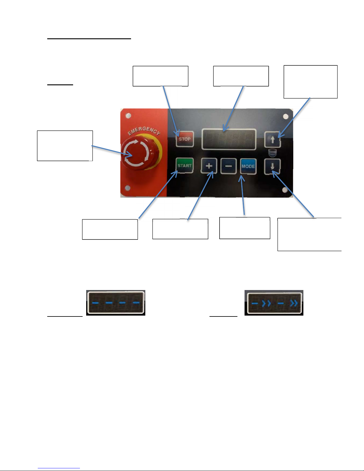
Best Mix control Panel
Figure 1 STOP
BUTTON DIGITAL
DISPLAY
BOWL
LIFT UP
BUTTON
STOP
EME
RGENCY
BUTTON
START
BUTTON SELECTIONS
BUTTONS SETTING
BUTTON BOWL
LIFT
DOWN
BUTTON
First of all be sure the Emergency stop button is released . The mixer can properly work
as Manual or under the Digital timer. If grid and bowl are in the correct position, you will
see 4 blue lines in the center of the lcd display. (figure 2a).
Figur
e
2a
figure 2b
In event of blue light blinking, double check the grid alignment or final bowl position. If
the light are fixed and you would like to operate manually, just press “START”. The Mixer
will work till you do not press “STOP” or turn the grid from its position.
While the mixer is running as manual , you will see on the digital display, blue lights
moving towards right as you can see (figure 2b). Just pressing “Stop” the mixer will
immediately stopped it-self and the blue light will come back fixed as “figure 2a”.

I
ns
tr
uc
ti
o
n
m
anua
l
CPL
-
4
0
8
o
f
19
WORKING WITH THE DIGITAL TIMER:
If you would like to set the Timer, please press button “MODE” . You should see onto the
digital lcd display, the last programmed time as “minutes: seconds” . (figure 3). In case you
agree with the timing already set, just press “START” and the mixer will begin to work and
the countdown will indicate the resting working time. When time get the 00:00 , the
planetary mixer will be automatically stopped.
Figur
e3
Setting the Timer:
If you need to set a different timing press for some seconds button “MODE”. You should
see the “minutes” blinking. Just pressing buttons “+” and “-“ is possible to change the mas
you prefer. Pressing once again the button “MODE” , you will be able to set “seconds” too.
To exit from setting, just press again button “MODE”. The time will stop blinking . Now
you are ready to press “start” once again and begin the working cycle.
Pay Attention:
The Best Line Planetary mixers have a mechanical variable belt drive system with 7
speeds. DO NOT CHANGE SPEEDS IF THE MIXER IS NOT RUNNING. Moving the
Speed lever while the mixer is not running, can cause serious problem on the Belt and
gears.
While the mixer is running, if you open the protection grid or move the bowl down, i twill be
automatically stopped.
Before begin to work with the planetary mixer, please check the speed lever position. To
avoid any kind of issues, we suggest to move the lever to the lower speed at every single
use. If you are going to use the Dough-Hook and the mixer start spinning at the fastest
speed, it might be broken in seconds.

I
ns
tr
uc
ti
o
n
m
anua
l
CPL
-
4
0
9
o
f
19
The mixer is provided with a lever to change the tool rotation speed. This mixer has 7
different
speeds. ATTENTION: ALWAYS change the speed while the mixer is moving to allow
the
variable pulley belt to position
correctly.
In order to remove the mixture, wait until the tool has stopped. Then turn the protection
grid.
Use the arrow êinto the control panel to lower the bowl and release the tool from
the
attachment sleeve. Remove the tool and release the bowl from the
handles.
The work load of the planetary mixers is established by the customer. Very many problems arise
from
improper use. If recommended amounts are exceeded, the quality of the product will suffer, as well as
the
duration of the mechanical organs of the mixer. See the following table for indications on maximum
amounts:
APPLICATION
INGREDIENTS
CPL
10
CPL
20
CPL
30
CPL
40
CPL
60
TYPE
OF
TOOL
POSIT
LEVER
M
i
x
w
it
h
55
%
wa
t
e
r
F
l
ou
r
+
W
a
t
.
Kg
3
6
9
12
18
Dough
-
hook
1
Pasta for
croissants
Flour
Kg.
2,5
5
7
9
15
Dough-hook
1
Pasta for
profiteroles
Flour
Kg.
2
4
6
8
12
Dough-hook
1
Meat
Kg.
5
10
15
20
30
Dough-hook
/butter
biter
1-2
Purée
Potatoes
Kg.
5
10
15
20
30
butter
biter
/whisk
1-2
Egg
white
Number of
eggs
16
32
50
70
96
Whisk
1-4
Biscuits
Number of
eggs
15
30
45
60
90
Whisk
1-3
Meringues
Sugar
Kg.
0,75
1,5
2,25
3
4,5
Whisk
1-4
Whipped
cream
Litres of
cream
2
4
5,5
7
10
Whisk
1-4
CONDITIONS FOR
USE:
Atmospheric conditions: The mixer needs to be installed inside of a lit, ventilated building, on top of a
solid
and level support. Temperatures from 5 to 40°C with humidity no greater than
90%.
Lighting: the light at disposal of the operator must comply with the type of work carried out, in relation
to
general lighting, according to the Standards in force. It must on any account be sufficient to read the
controls
and danger signs and must not blind the
operator.
§Vibrations: in correct working conditions, vibrations do not create dangerous
situations.
§Noise emissions: 70 dbA for normal
use.
§Electromagnetic environment: the machine has been built to work correctly in an industrial type
of
electromagnetic
environment.
Environments with risk of explosion: An atmosphere capable to being transformed into
an
explosive atmosphere due to room and/or operating conditions is defined a potentially
explosive
atmosphere.
The mixer was not built to work in environments with potentially explosive
atmospheres.
IDENTIFICATION, POSITION OF THE OPERATOR AND DANGEROUS
AREAS.
I
ns
tr
uc
ti
o
n
m
anua
l
CPL
-
4
0
10
o
f
19
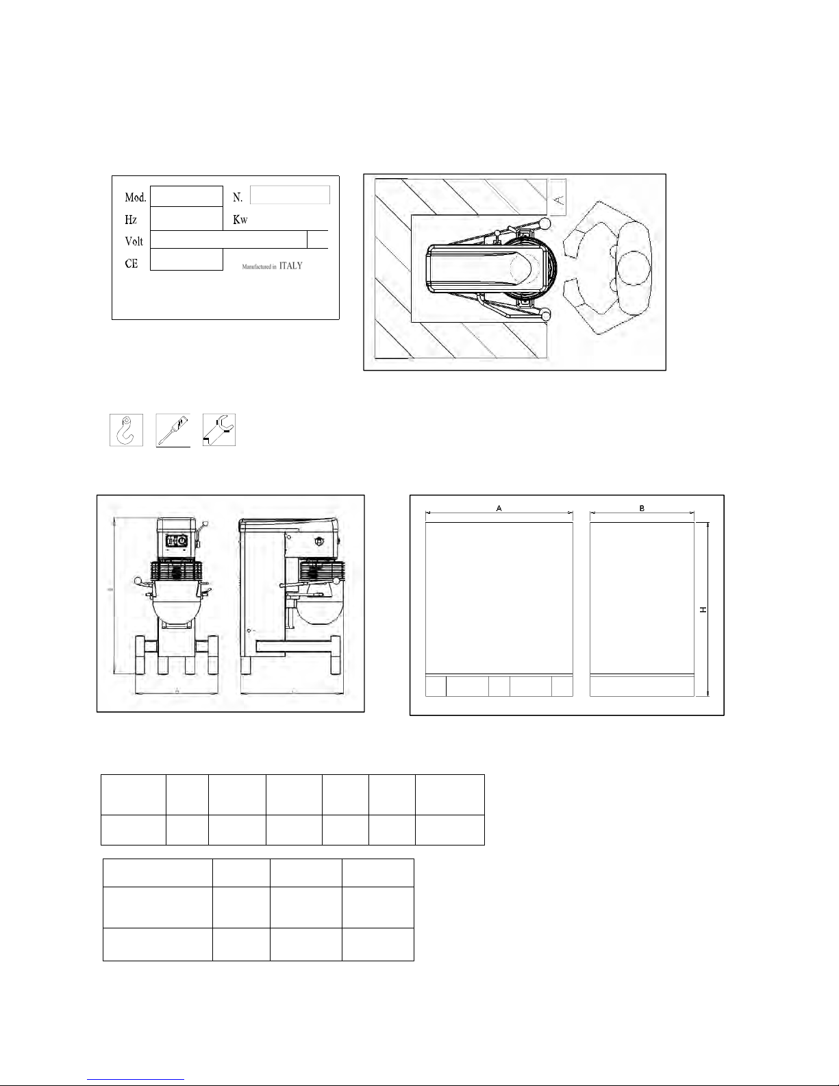
There is a plate on the back of the mixer like the one shown which carries indications concerning
the
manufacturer, the type of machine, serial number, electrical features, frequency, absorbed power and
the
number of phases and the year of construction. The figure at the side shows the position of the plate, that
of
the operator respect to the mixer and the AS danger area which must be free from people for a distance A
=
250
mm.
TECHNICAL DATA, PACKAGING, DIMENSIONS AND
WEIGHT.
There are four types of packaging: machine on pallet wrapped in cellophane, machine on
pallet
in cardboard box, machine on pallet in wooden cage, machine on pallet with
crate.
Model
A
mm
B
mm
C
mm
Weig
ht
[Kg]
Bowl
litres
Power
[Kw]
CPL
40
700
1290
920
204
40
1,5
Packaging
A
mm
B
mm
H
mm
Pallet +
cardboard
box
950
740
1610
Cage
1110
900
1550
I
ns
tr
uc
ti
o
n
m
anua
l
CPL
-
4
0
11
o
f
19
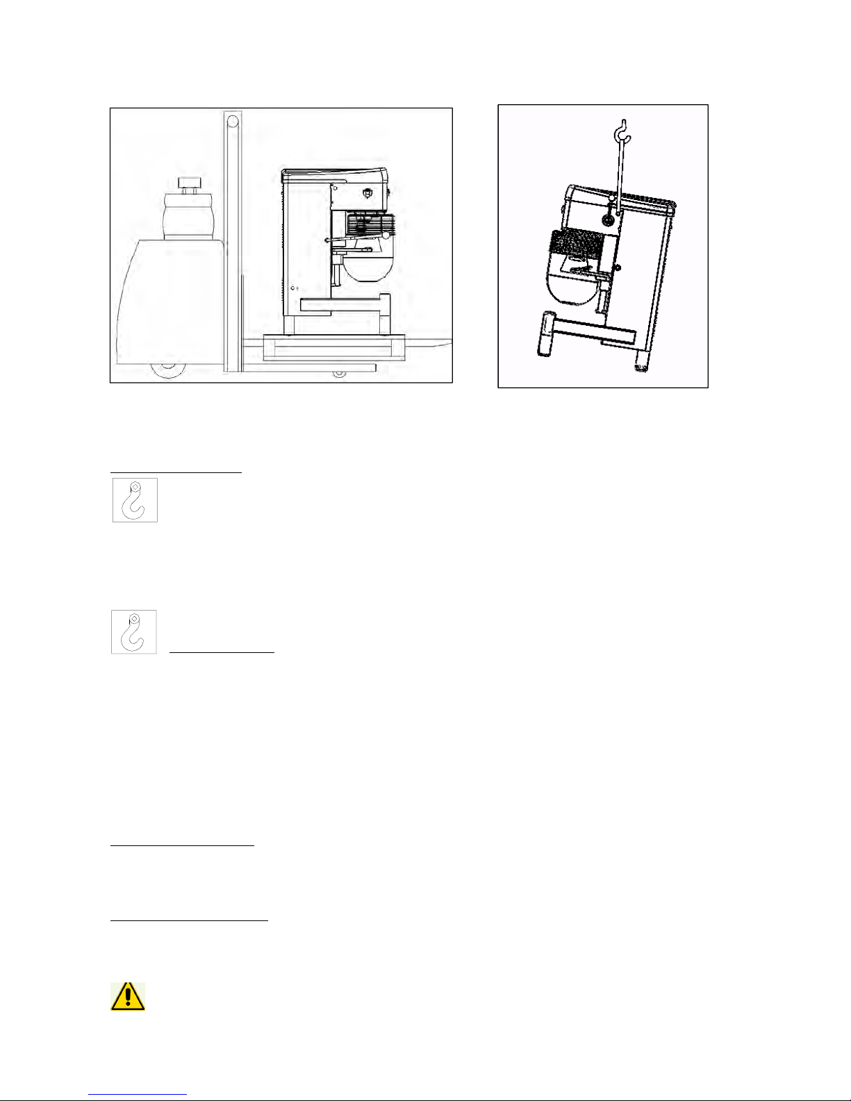
TRANSPORTATION AND
HANDLING.
Machine without pallet.
Due to its instability , the mixer must be handled with a suitably-sturdy strap, having it pass
below
the head, as in the figure at the
right.
Before lifting, stand the grid up
vertically
§Make sure the lift equipment is adequate for the load. Work in an empty area.
During
movement, always keep the load as close to the ground as
possible.
§Use the
required
P.P.E.
§The mixer inclines slightly by 10-15 degrees
when
lifted.
Lifting standards with lift truck: always use a pallet when handling the
mixer.
Machine on pallet.
§Make sure the lifting device is adequate for the
load.
§Widen the lifting forks as much as possible and make sure they come out from
the
pallet.
§Work in an area free from persons
and
animals.
§During movement, always keep the load as close to the ground
as
possible.
§Use the
required
P.P.E.
STORAGE:
Storage of packed mixer:
The mixer must be stored in a closed and covered place, on a smooth and solid surface protected from
dust
and filth, sheltered from atmospheric agents and hygienically
safe.
The temperatures must remain between –20 and +50°C, and humidity no greater than
90%.
Storage of unpacked mixer.
If the mixer has already been unpacked, in addition to that above, it must be lifted from the ground with
a
pallet or other and covered in order to protect it from humidity, dust and filth. If wrapped in cellophane
or
another type of plastic, avoid airtight closing below the mixer in order to prevent corrosion linked
to
condensate.
ATTENTION! The mixer must not be stored
outdoor!!

I
ns
tr
uc
ti
o
n
m
anua
l
CPL
-
4
0
12
o
f
19
INSTALLATION
The mixer must stand in a vertical position, on a smooth surface sufficiently sturdy for the load
(floor
with resistance over 20 km/cm2). If in danger of tipping over, anchor the mixer to the floor using
4
plugs or bolts with a traction resistance over kg 300
(M8).
Connection to electrical
mains
The electrical connection must be carried out by a specialized electrician, according to the
modalities
and standards in force in the country where it is installed. Make sure that the voltage and
frequency
of the system are the same as those on the mixer identification plate. Incorrect connection
makes
the warranty
void.
PRESERVATION OF THE
MACHINE
Storage before a long period out of
service
Clean the mixer
thoroughly.
Disconnect it from the electrical
mains.
If possible, put it back into its original
packing.
WARRANTY
TERMS
Validity: The warranty starts from the delivery date and lasts 12 months,
if:
§The mixer was not damaged during transportation, and it was installed, commissioned, used
and
serviced as prescribed in this
manual.
§It was not tampered with, modified and no unintended tools were installed on
it.
§It did not undergo modifications or repairs carried out by the customer or third parties in
an
incompliant fashion or without the prior consent of the
supplier.
The following conditions constitute improper use of the
mixer:
•
Loading more than what is allowed or use of unsuitable
ingredients.
•
Cleaning with unsuitable tools or instruments that can scratch the bowl or damage the mixer or
paint.
•
Use of the mixer in unsuitable
places.
Modality for granting the warranty
If the customer finds defects in the mixer, he must immediately inform the supplier, who will carry out a
quick
analysis of the lack of compliance and will establish the intervention mode with the
customer.
After agreement with the supplier, the customer must provide him with the needed time and opportunity
to
carry out modifications, improvements, repairs or the supply of spare parts which the supplier
deems
reasonably necessary. If this does not occur, the supplier will not be held
liable.
Parts subject to wear
Some components are scaled for a life duration far longer than that of normal mixer use during the time of
its
warranty. Breakage or malfunctioning of these pieces depends on their use. They are therefore
considered
parts subject to wear and are not included in the warranty, unless they manifest evident defects in the
parts
or
machinery.
The parts subject to wear are: transmission belts, motors, bearings and bowl.

I
ns
tr
uc
ti
o
n
m
anua
l
CPL
-
4
0
13
o
f
19
Control
Interval
Method
a
F
Control
Interval
Method
m
F
Control
Interval
Method
a
F,
M
CLEANING AND MAINTENANCE
OPERATIONS.
CONTROL OF INSTALLED SAFETY SYSTEMS AND ELECTRICAL
SYSTEM
The installed safety systems and the electrical system are subject to periodical checks carried out
by
a specialized
electrician.
Key of control
intervals:
(INTERVAL)
Key of how to carry out the
controls:
(METHOD)
d =
daily.
w =
weekly.
m =
monthly.
a =
annually.
O = observation: requires simple eye check (i.e. alarm
light)
F = Function: requires a physical control of the action (i.e. pressing
the
emergency button the mixer must
stop)
M = Measurements: requires a control with an appropriate instrument
(i.e.
control of earthling
values).
Master switch.
Purpose: protection of power
line.
Function: this equipment separates the machinery from the mains, it is placed
on
the upright of the mixer, downstream the differential protection
board.
Stop circuit and safety micro switch of grid.
Purpose: to stop the mixer immediately and unconditionally. Function:
pressing
the STOP button or lifting the protective grid cuts the motor power, stopping
the
mixer totally and not systematically. To restore functioning of the machinery,
the
operator must start the cycle once again by pressing the START
button.
Controls of system
Periodically the mixer's automation functioning and earthling must be
checked.
The operating modes, safety functions, terminal board contacts need to
be
controlled as well as the integrity of the cables, luminous LEDs and
earthling
system.
ROUTINE
MAINTENANCE.
DO NOT CARRY OUT ANY MAINTENANCE OR CLEANING WITH ELECTRICITY
CONNECTED
DO NOT CARRY OUT ANY MAINTENANCE OR CLEANING WITH ELECTRICITY CONNECTED The
mixer
does not require particular maintenance operations. After the first three months of work, check the wear
of
the
belt.
Every 4 ÷6 months, grease and oil the points indicated in the following layout (use MOLYKOTE 165
LT
grease).

I
ns
tr
uc
ti
o
n
m
anua
l
CPL
-
4
0
14
o
f
19
grease
nipples
Grease
manually
Grease
manually
Should a power
cable be
damaged, replace
it with a
H07RN/F
cable with a 3x1.5
mm2 section.
EXTRAORDINARY
MAINTENANCE:
A
Cleaning: the mixer is not jet-
proof. Do not wash it
with
running water. Clean it with
a
moist cloth and
neutral
detergents, such
as
degreasing agents based
on
Castile
soap
To carry out interventions not specially mentioned in the manual,
refer
to personnel authorized by C.P. SRL. To replace the motor or
the
circuit boards, or else if the mixer falls, contact our assistance
service
for an intervention on site or else an overhaul at the
factory
I
ns
tr
uc
ti
o
n
m
anua
l
CPL
-
4
0
15
o
f
19
PERIODICAL
MAINTENANCE.
DAILY CLEANING AND CONTROL
OPERATIONS:
•
Cleaning outside surfaces of the bowl and tools with cloth and neutral degreasing
agent.
•
Operative and emergency controls
check.
MONTHLY, ANNUAL MAINTENANCE
OPERATIONS
Monthly
maintenance:
•
Thorough cleaning of the
mixer.
•
Operative and emergency controls functioning
check.
•
Mixer's external components' check: tools, bowl, protective
grid.
•
Transmission noise
check.
Annual
maintenance:
•
Thorough cleaning and check of entire
machinery.
•
Thorough check of transmission
organs.
•
Bolt tightening check for entire
machinery.
Bolt tightening
torques.
M6
M8
M10
M12
M14
M16
Mixer screws (8.8)
[Nm]
.7
23
47
80
130
1 6
Stop rod screws (10. )
[Nn]
13.6
33
6
113
180
275
Mixer screws A2
[Nm]
§Installed safety systems
check.
SPARE
PARTS:
C.P. SRL reserves the right to carry out all the modifications that it deems necessary for its
mixer
models. It is therefore always necessary to
specify:
•
Type of
mixer
•
Serial
number
•
Year of
construction
•
Position, description, item code and desired amount of pieces
requested.
Send the request to: C.P. SRL via Perotti 5, 25125 Brescia (BS)
Italy
MAIN
COMPONENTS:
•
Raw materials used: almost all of the components of the mixer are made of steel, cast iron,
brass
and plastic. All of these components can be disposed of easily and do not represent a danger
for
environmental pollution and/or personal safety. Separate the different materials for
subsequent
reuse or differentiated waste
collection.
•
The electrical system must be dismantled and disposed of through a specialized
company.
•
Treatment of surfaces: painting of metallic surfaces with products compatible for food
use.
•
Sigma packaging replies fully with that required by Directive 94/62/EC and by Legislative
Decree
05/02/97 n. 22 (and subsequent amendments and integrations). They thus can easily
be
assimilated with city waste and can be inserted in any public differentiated waste
program.
DISMANTLING AND WASTE
DISPOSAL:
The purchaser is responsible for putting the mixer out of service, who must comply with local standards
and
regulations. Dismantling of mechanical and electrical parts must be entrusted to competent
personnel.

I
ns
tr
uc
ti
o
n
m
anua
l
CPL
-
4
0
16
o
f
19
SPARE PARTS LIST
*
*: this is a brand new generation of C.P.SRL planetary mixers, the following chart can be little bit different
from the machine you have. In case contact the factory to get the updated one. We will soon provide you the
real line diagrams of it.

I
ns
tr
uc
ti
o
n
m
anua
l
CPL
-
4
0
17
o
f
19
SPARE PARTS LIST TABLE:
Position
Quantity
Code
Description
1 1 095016-A Driven pulley CPL-40
2 1 101022-5 Planetary shaft CPL-60
3 1 101023-2 Driving bevel gear Z22 CPL-60
version with reduction gear
4 1
1
1
1
097201 Silkscreen printing CPL20
Timer
START/STOP button
ON/OFF switch
5 2
4
2
194021-1
194022-1
194023-1
Long grid wheel pin
Grid guide wheel
Short grid wheel pin
6 1 095020-2 Tool holder shaft CPL-40
7 1
1
1
095058
095216
095217
Thin wire whisk CPL40
Cast blade CPL40
Cast spiral CPL40
8 1 095122-1 Bowl CPL-40
9 1 095050-2 Bowl lifting rod CPL-40
10 2 095049-3 Bowl lifting plate CPL-40
11 4 095052-1 Plate distance pad
12 1 MARKET Motor Gr.90 B14 for CPL-40
13 1 095036-2 Cogwheel Z15
14 1 095008-9 Motor seat CPL-40,CPL-60
15 1 095208-1 Top casing CPL-40
16
101181-1 2.5 module rack for CPL-40
17 1 097013-4 Planetary pinion CPL-20
18 1 101070-2 (50 Hz)
101017-3 (60 Hz) Countershaft CPL-60
19 2 095013-5 Variable semi-pulley CPL-40
20 1 095080-3 Variator belt
33x10x1322
21 4 MARKET 38x42x15 bushes
22 1 095012-7 Variable pulley shaft CPL-40
23 1 185016 Reduction gear support
24 1 185017 Reduction gear connection shaft
25 1 097016-3 Driven bevel gear Z22 M3
26 2 MARKET Bearings 47-20-14 (6204)
27 1 MARKET Bearings 30-62-16 (6206)
28 1 MARKET Bearings 80-40-18 (6208)
29 2 MARKET Bearings 52-25-15 (6205)
30 2 MARKET Bearings 80-40-18 (6208)
31 2 MARKET Bearings 62-25-17 (6305)
I
ns
tr
uc
ti
o
n
m
anua
l
CPL
-
4
0
18
o
f
19
BLOCKAGE OF MACHINERY AND NECESSARY
REMEDIES
OPERATION
ANOMALIES
POSSIBLE
CAUSES
REPAIR
Turning the master switch
into
position, the warning light
does
not turn
on
1) Plug not inserted correctly or
wires
detached
1) Check
connection
Pressing the START button,
the
mixer does not
start
1) The slide is not in position or
the
front grid is not
closed
2) Safety micro switch
anomalies
1) Lift the slide and reposition
it
after having closed the
front
grid
2) Replace the micro
switch
Intermittent
noise
1) Lack of grease in
transmissions
(gears)
1) Grease as shown in
previous
layout (page
13)
Continuous
noise
2) Check the efficiency of
the
bearings
1)
Replace
the
bearings

I
ns
tr
uc
ti
o
n
m
anua
l
CPL
-
4
0
19
o
f
19
Obligations of informing users
Information model for users of “professional”
products
INFORMATION FOR
USERS
In compliance with art. 13 of the Legislative Decree of July 25, 2005,
n.
151 “Implementing of Directives 2002/95/EC, 2002/96/EC
and
2003/108/EC, relative to the reduction of the use of
hazardous
substances in electrical and electronic appliances as well as disposal
of
waste”
The symbol of the barred waste bin on the appliance or
its
packaging indicates that the product at the end of its useful life
it
must be disposed of separately from other
waste.
Differentiated waste collection of this appliance having reached
the
end of its life is organised and managed by the manufacturer.
The
user who desires to dispose of the present appliance must
therefore
contact the manufacturer and abide by the system that has
been
chosen to allow separate collection of the appliance when
reaching
the end of its
life.
Adequate differentiated waste collection for successive
recycling,
treatment and environmentally compatible disposal contributes
to
prevent negative effects on the environment and on human
health
and favours the reuse and/or recycling of the materials making
up
the
appliance.
Illicit disposal of the product by the user entails the application
of
administrative sanctions foreseen by Standards in
force.
Table of contents
Other CP Mixer manuals

Popular Mixer manuals by other brands


ALLEN & HEATH
ALLEN & HEATH ZED 12 FX user guide

SEVERIN
SEVERIN HM 3812 Dimensions

Phoenix Audio Technologies
Phoenix Audio Technologies Stingray MT700 user manual

Art
Art MyMONITOR Specifications

Oster
Oster MIXMASTER 2700 instruction manual

smaky
smaky SL-800A Installation, operation and maintenance instructions


