CR ROMULUS User manual

OWNERS MANUAL
ROMULUS LINE LEVEL INTEGRATED
AMPLIFIER

ROMULUS
INTEGRATED VALVE AMPLIFIER
C.R. manufacture a range of high quality tube amplifiers which have
established a world wide reputation for high quality audio performance.
Our integrated amplifiers demonstrate that high quality audiophile performance
and cleanly styled aesthetics are compatible and not mutually exclusive !
We hope that our products will combine with other elements of your hi-fi
system to provide hours of musical enjoyment.
Please read the following information which will help you obtain the best results
from your C.R. tube amplifier.
INSTALLATION
Carefully unpack the amplifier, it is recommended the packaging is retained for
reuse if the unit is to be transported later.
The standard finish for C.R. amplifiers is Gloss Black paint and polished
stainless steel. These are very durable but the use of cleaning agents,
abrasives and polishes should be avoided if the high quality finish is to be
retained. Dusting with a soft cloth is all that will be required to maintain the
product in good condition.
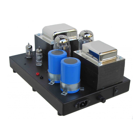
Some amplifier models are delivered with the output tubes removed and
individually packed. Each tube is marked with a number which corresponds
to the position in which it should be placed. (See fig. 1)
Carefully insert each tube in turn, ensure tubes are fitted in the correct
orientation and pushed firmly into their sockets.
The optional protective cover or cage is fitted to the amplifier by screws which
fit into pre-drilled holes in either side of the main chassis. Do not attempt to fit
or remove the cover while the amplifier is in use.
Use only the moulded mains cable provided.
Ensure the amplifier is connected to a mains earth at all times during use.

INSTALLATION cont.
Position the amplifier on a suitable support table or shelf capable of supporting
the units weight (please see the separate specifications for each model). Allow
adequate space for ventilation.
GROUND LIFT SWITCH
All amplifiers are fitted with “Ground Lift” switches to simplify installation of
multi amplifier systems.
This switch removes the ground or earth connection between the amplifier
electronics and chassis. The switch does not affect the mains earth connection,
it is essential that the amplifier is always connected to a mains earth.
REMOTE CONTROL
The Romulus model amplifier is available with an optional remote control
system which provides control of volume level and mute via a standard infra
red remote control key pad. The remote control option is not available as a
retro fit modification it is only available if specified when ordering.
When the unit is switched on the control system sets the output to Mute and
resets the motorised volume control to zero. To play music first press the mute
button on the handset and the advance the volume level with the “up” arrow.
CONNECTIONS AND CABLES
Use high quality phono plugs and interconnect cables for connection to source
components.
It is recommended that all interconnect cables are kept as short as possible to
minimise signal loss. Low capacitance cables are preferred and generally
these types will minimise losses.
Connect the amplifier to loudspeakers with a nominal impedance of at least
6 Ohms for optimum performance. Loudspeaker cables with a minimum
cross section of 1.5 sq. mm are recommended.

CONNECTIONS AND CABLES cont,..
Take care no loose strands of wire are visible between the loudspeaker
terminals, short circuits may damage the amplifier.
After making all connections connect the amplifier to a mains supply, ensure
the volume control is turned down to minimum and switch on.
After a few
seconds the valve heaters will begin to glow. After approximately 15
seconds adjust the volume control to the desired sound level, the sound
quality should be crisp and clear. If there is audible distortion or unwanted
noise switch off and check all wiring and connections.
If problem persists consult your dealer or telephone 01702 469055 for advice.
In the event of the amplifier becoming faulty please contact your retailer of
return the unit for manufacturers repair. Do not attempt to dismantle, modify or
repair the amplifier, to do so may invalidate the manufacturers warranty.
NOTE: No user replacement parts are fitted, return to manufacturer for repair.
ENSURE THE VALVE AMPLIFIER IS NOT SWITCHED ON WITHOUT
THE LOUDSPEAKERS CONNECTED.
OPERATION
Valves, or Themionic Tubes, are rugged components but they have a finite
operating life of several thousand hours continuous use.
Observation of the
following points will help prevent premature failure and ensure many hours
of listening
pleasure.
1Valve amplifiers warm up rapidly, it is not necessary or desirable
to leave the amplifier permanently switched on to ensure the best
performance. It is recommended that the amplifier should be switched
off when not in use to conserve valve life.
2Do not switch the amplifier on when hot, i.e. immediately after prior use,
always allow the valves to cool completely before switching on again.
3Always use the amplifier within it’s performance envelope, persistent
overloading, indicated by “clipping”, a clearly harsh and audibly
distorted sound, will shorten tube life.
The valve set supplied with the amplifier is guaranteed for 6 months only.

VALVE REPLACEMENT
The tubes are the heart of an amplifier, they have a finite operating life and will
finally require replacement. Routine replacement is not necessary, an obvious
deterioration in sound quality, output power or both, will be clearly apparent.
Tube replacement is a simple procedure and may be carried out by your
dealer, chosen by C.R. for his technical expertise, who will also inspect the
amplifier. Alternatively the user may install the replacement valve providing
the following procedures are carefully followed.
Valves may be replaced as either a complete set of drive and output valves or,
depending upon the age and level of use, only the output valves may require
replacement.
1Switch off the amplifier , disconnect the mains supply and allow the
valves to cool completely.
2Unpack the new tubes and inspect for obvious damage, e.g. bent pins
of broken glass.
3Carefully unplug and remove each valve and replace with a new
one. Ensure the new valve has the same identifying part number as
the component it is replacing.
4For optimum performance the output tube bias should be
re-calibrated for a new set of tubes, your dealer will be
able to install and re-set the tube bias.

Romulus Line Level Integrated amplifier
SPECIFICATION
INPUT SUPPLY 115/230v 50/60Hz
POWER CONSUMPTION 250 VA
OUTPUT POWER 35 W.P.C. 8 Ohm load
Suitable for loud speakers of 4 to 16 ohms
SENSITIVITY 100mV for full output on all inputs.
INPUTS 5 line level inputs via rear mounted Phono
sockets
VALVES 3 off type 12AX7 (ECC83)
2 off type 12AU7 (ECC82)
4 off type 6L6WGC output valves.
DIMENSIONS 430mm wide x 150mm high x 350mm deep
(overall)
WEIGHT 15.5 Kg.
PACKED DIMENSIONS 510mm x 410mm x 240mm
weight 18 Kg.

SAFETY WARNING
Valve amplifiers contain high voltage DC (Direct Current) power supplies,
these high voltages can be Very Dangerous.
1Do not remove any of the cover panels.
2Do not attempt to operate the amplifier with the cover panel removed
3The amplifier output valves operate at very high surface temperatures,
keep out of reach of children and pets.
4Do not touch the tubes (valves) when the amplifier is in use or while
they are hot.

INPUT SOCKETS
12AX712AX7
12AX7
12AU7 12AU7
6L6WGC 6L6WGC 6L6WGC 6L6WGC
6L6WGC
6L6WGC
6L6WGC
6L6WGC
12AX7
12AX7 12AX7
12AU7 12AU7
INPUT SELECTOR
SWITCH
VOLUME
CONTROL POWER
SWITCH
'SPEAKER
TERMINALS
POWER INLET
ROMULUS INTEGRATED AMPLIFIER

Made in England by
C. R. Electronic Design
Wansfell House Briar Close,
Hawkwell,
Hockley,
Essex, SS4 5HD.
Tel. 44 (0) 1702 200111
Supplied by :-
Table of contents
