manuals.online logo
Brands
  1. Home
  2. •
  3. Brands
  4. •
  5. Redback
  6. •
  7. Amplifier
  8. •
  9. Redback A 1922A User manual

Redback A 1922A User manual

www.redbackaudio.com.au Redback® Proudly Made In Australia 1
Redback® 60/120Watt Amplier Modules
Operating Manual
A 1922A 60W 100V Amplier Module
A 1932A 120W 100V Amplier Module
This module is designed for use in emergency evacuation
systems and is powered by an external 24V DC source. It
accepts a line level audio input and produces a 100V line
output via a transformer. It also features short circuit,
overload and thermal cutout protection, and is constructed
on a steel chassis. Designed with reliability and robust
performance in mind, it is the ideal audio power source for
evacuation systems, or any application which requires a DC
powered 100V line amplier.
FEATURES
• Powered by nominal 24V DC
• 100V line audio output
• Line level audio input - 600mV
• Short circuit, overload, and thermal cutout protection
• Bolt-in chassis construction
• Australian designed and assembled
INSTALLATION
Connecting the Audio Source
The input connector for the audio source is the 3 way screw
terminal block labelled “AUDIO IN ”, (see gure 1 for the
PCB location and pinouts). This input may be used with
balanced (3 wire) or unbalanced (2 wire) audio sources.
When connecting an unbalanced (2 wire) source, jumper the
GND and -ve connections on the terminal connector (See g
1 inset).
The amp module’s input is suitable for impedances between
600Ω and 10kΩ. The high impedance of 10kΩ enables
multiple amplier units to be paralleled together when
driven from a low impedance source ie 600Ω.
An output connector (LOOP OUT), feeds the input audio
directly out and has been provided for easy connection of
multiple modules feeding off the same input source.
Connecting Power
Connect 24-28V DC to the power supply input (24V DC IN)
terminal as per g.1.
Ensure that the power supply is capable of providing the
necessary current (see specications).
A 24V DC output has been provided with a maximum current
draw of 1 amp to provide power to external devices.
Connecting the speaker load
Connect the output load to the (TO LOAD) terminals shown
in g.1. Speakers fitted with 100V line transformers may
be connected. Always ensure the total load of the fitted
speakers does not exceed the rated output of the amplifier
otherwise damage may result. When fitting speakers with
line transformers the impedance of the load cannot be
measured using a standard multimeter. An impedance
meter is required. Fig 2 lists the impedance at certain loads
of speakers fitted with 100V line transformers. So for a
total load of 120 watts using 100V line transformer fitted
speakers the impedance of the speaker load should be 80Ω.
LED INDICATORS
Power
This indicates that the unit has power.
Signal Present
This indicates that an audio signal has been detected at the
audio input terminals.
Fault
The Fault LED indicates the unit has a fault condition. Check
the other indicators for further diagnosis.
Temp
The Temp LED will illuminate when the unit shuts down due
to excessive temperature rise.
Overload
The overload LED will illuminate when the unit’s output is
limited due to excessive load on the speaker outputs.
Limit
This LED indicates that the amplier has reached it’s maximum
output level.
Protect
This LED indicates that the unit has gone into protection
mode due to internal failure
www.redbackaudio.com.auRedback® Proudly Made In Australia2
Redback® 60/120Watt Amplier Modules
* Specications subject to change without notice.
Distributed by Altronic Distributors Pty. Ltd. Perth. Western Australia. Phone: 1300 780 999 Fax: 1300 790 999
SPECIFICATIONS
Output Power: A 1922A: ..................................60W RMS
A 1932A: ................................120W RMS
Current Draw: A 1922A: 4A at full load, 220mA Quiescent
A 1932A: 8A at full load, 220mA Quiescent
Freq. Response: .............................................50Hz - 12kHz
Distortion: ...............................................................< 0.6%
Signal to Noise Ratio:................................................. -91dB
Sensitivity: .......................................................600mV RMS
Fuse Rating and Type: A 1922A:......................4A M205
A 1932A:.....................7.5A M205
Dimensions (mm): A 1922A: .......210W x 170D x 80H
A 1932A: .......210W x 170D x 87H
TROUBLESHOOTING
Fuse blows: Check speaker loads and replace fuse with 20
Amp blade fuse.
Fuse continually blows: Disconnect load, apply power. If
fuse blows again, refer unit to authorised service centre.
Overload LED illuminates: Check speaker types and
ratings to ensure the amplier is not overloaded, and that
there are no shorts on the speaker line.
Temp LED illuminates: In this condition check the unit for
adequate ventilation. Check also speaker types and ratings
to ensure the amplier is not overloaded, and that there are
no shorts on the speaker line.
LED INDICATORS
OUTPUT TRANSFORMER
POWER
INPUT
SPEAKER
OUTPUT
(100V)
- +
24V DC
IN
- +
24V DC
OUT
- GND +
INPUT
- GND +
LOOP OUT
AUDIO INPUT
LINK GND & -VE INPUTS FOR
AN UNBALANCED
INPUT
+ GND -
Fig 2
Fig 1
i
Wiring speakers in parallel for 70/100V line: Where several speakers are to
be used at one time, on one circuit, it becomes necessary to use speakers fitted
with line-matching transformers. This is to overcome the effects of connecting
speakers in parallel and cable losses. The amplifier generally has an output
voltage of 100 volts (70 volts is typically used in North America, however
operation is similar). In this configuration the total wattage load on the amplifier
is derived from adding all the line transformer primary tap ratings together. For
example, 70 one watt speakers will have a total speaker load of 70 watts. Or
alternatively, it is conceivable to connect 100 one watt speakers to a 100 watt,
100 volt line amplifier.
Measuring 70/100V Line Speaker Impedance: To measure amplifier system
load, you must use an impedance meter in order to measure the ac resistance
of the connected speaker network. Impedance cannot be measured with a
standard multimeter, as this measures the dc resistance. Use the Altronics
Q 2003 or similar impedance meter.
About 70V & 100V Line Speaker Systems
Load 70V 100V
0.5W 9.4kΩ 20kΩ
0.66W 7.12kΩ 15kΩ
1W 4.7kΩ 10kΩ
1.25W 3.76kΩ 8kΩ
2W 2.35kΩ 5kΩ
2.5W 1.88kΩ 4kΩ
3W 1.56kΩ 3.3kΩ
5W 940Ω 2kΩ
7.5W 626Ω 1.3kΩ
10W 470Ω 1kΩ
15W 313Ω 666Ω
20W 235Ω 500Ω
30W 156Ω 333Ω
40W 117Ω 250Ω
60W 78Ω 166Ω
100W 47Ω 100Ω
125W 37Ω 80Ω
250W 19Ω 40Ω
500W 9.4Ω 20Ω

This manual suits for next models

1

Other Redback Amplifier manuals

Redback A 4230A User manual

Redback

Redback A 4230A User manual

Redback A 4020B User manual

Redback

Redback A 4020B User manual

Redback A 4024 User manual

Redback

Redback A 4024 User manual

Redback A 4116 User manual

Redback

Redback A 4116 User manual

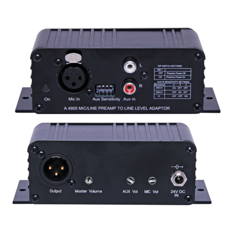
Redback A 4905 User manual

Redback

Redback A 4905 User manual

Redback A 4036 User manual

Redback

Redback A 4036 User manual

Redback Phase 4 Installation guide

Redback

Redback Phase 4 Installation guide

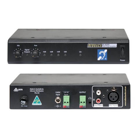
Redback A 4205 User manual

Redback

Redback A 4205 User manual

Redback A4260B User manual

Redback

Redback A4260B User manual

Redback A 4031B User manual

Redback

Redback A 4031B User manual

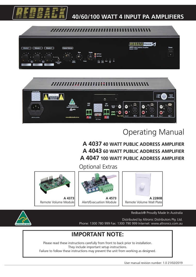
Redback A 4037 User manual

Redback

Redback A 4037 User manual

Redback A 4017 User manual

Redback

Redback A 4017 User manual

Redback A 4387A User manual

Redback

Redback A 4387A User manual

Redback A 4372 User manual

Redback

Redback A 4372 User manual

Redback A 4931 User manual

Redback

Redback A 4931 User manual

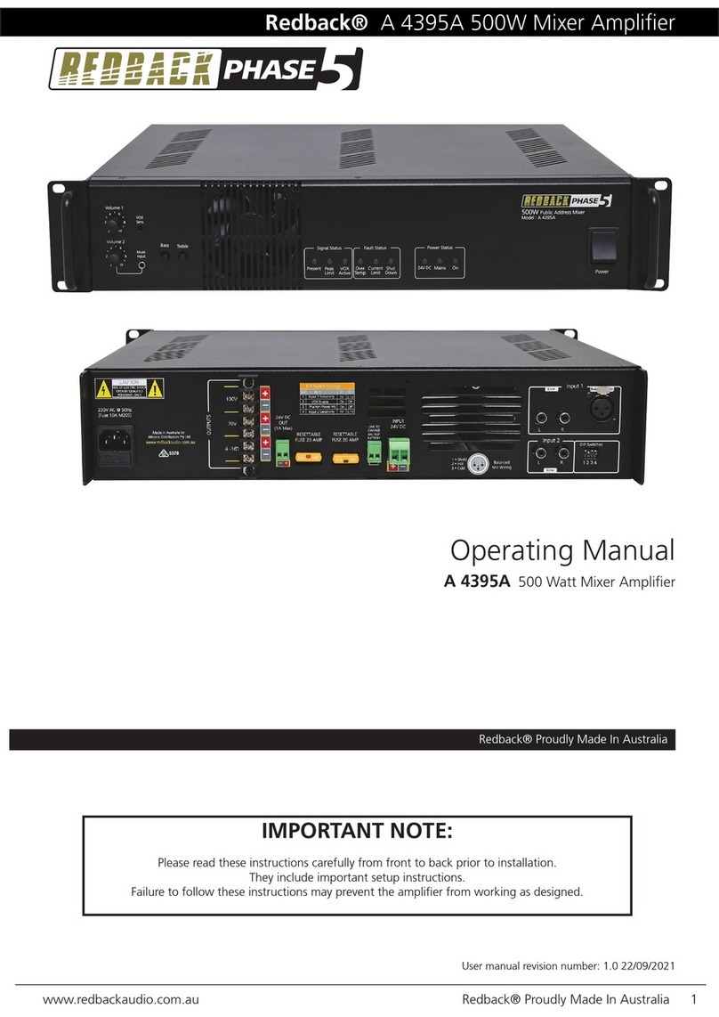
Redback PHASE 5 A 4395A User manual

Redback

Redback PHASE 5 A 4395A User manual

Redback A 4861 User manual

Redback

Redback A 4861 User manual

Redback A 4314 User manual

Redback

Redback A 4314 User manual

Redback A 4860 User manual

Redback

Redback A 4860 User manual

Redback A 2082 User manual

Redback

Redback A 2082 User manual

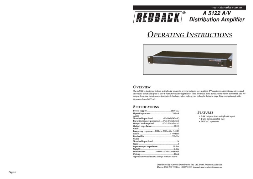
Redback A 5122 User manual

Redback

Redback A 5122 User manual

Redback A 4937 User manual

Redback

Redback A 4937 User manual

Redback A 4210 User manual

Redback

Redback A 4210 User manual

Redback A 4260A User manual

Redback

Redback A 4260A User manual

Popular Amplifier manuals by other brands

Pyramid SEA-2500 user guide

Pyramid

Pyramid SEA-2500 user guide

RJM DA-14 user guide

RJM

RJM DA-14 user guide

Simaudio NORTH MOON 791 user manual

Simaudio

Simaudio NORTH MOON 791 user manual

Linear Tube Audio MZ2 Series user guide

Linear Tube Audio

Linear Tube Audio MZ2 Series user guide

McIntosh C11 - SERVICE manual

McIntosh

McIntosh C11 - SERVICE manual

Pyle PLMRA120 user manual

Pyle

Pyle PLMRA120 user manual

AMT S-Drive FX-Drive Series user manual

AMT

AMT S-Drive FX-Drive Series user manual

Gefen 1x4 VGA the Hub user manual

Gefen

Gefen 1x4 VGA the Hub user manual

Lab.gruppen FP+ Series FP 10000Q Technical data

Lab.gruppen

Lab.gruppen FP+ Series FP 10000Q Technical data

Tube Technology Fusion HB70 user manual

Tube Technology

Tube Technology Fusion HB70 user manual

Audiovox Phase Linear UPA224 owner's manual

Audiovox

Audiovox Phase Linear UPA224 owner's manual

NAD CI 720 Quick setup guide

NAD

NAD CI 720 Quick setup guide

Marshall Amplification DSL100HR Service manual

Marshall Amplification

Marshall Amplification DSL100HR Service manual

ROCKNA AUDIO Wavelight owner's manual

ROCKNA AUDIO

ROCKNA AUDIO Wavelight owner's manual

Simaudio AURORA owner's manual

Simaudio

Simaudio AURORA owner's manual

Sony XM-404EQX operating instructions

Sony

Sony XM-404EQX operating instructions

Crown DCi 8 600DA Operation manual

Crown

Crown DCi 8 600DA Operation manual

LABTEC Dialog user guide

LABTEC

LABTEC Dialog user guide

manuals.online logo
manuals.online logoBrands
  • About & Mission
  • Contact us
  • Privacy Policy
  • Terms and Conditions

Copyright 2025 Manuals.Online. All Rights Reserved.