CRAFTMASTER STAINLESS KEGGERNUAT User manual
KEGGERNUAT
Two-Head Semi-Automatic Keg Washer
Opperation Manual
CRAFTMASTER STAINLESS
RANCHO CORDOVA, CA
(916) 750 - 4677
craftmasterstainless.com

2
TABLE OF CONTENTS
CAD DRAWINGS
PARTS AND COMPONENTS
ELECTRICAL REQUIREMENTS
CHECKING AND CHANGING POLARITY
COMPRESSED AIR AND CO2 REQUIREMENTS
SOFTWARE OVERVIEW
CHANGING PRESET PARAMETERS
CLEANING STAGES
OMRON TEMPERATURE CONTROLLER - HEATING ELEMENT
RECOMENDED DEFAULT PARAMETERS
PRESSURE CONTROL INSTRUMENT - CO2 FILL PRESSURE
OPERATION GUIDE AND SAFETY
OMRON MANUAL
3
4
5
6
8
9
10
12
13
18
17
19
20
Check out our quick start guide video series.
** VIDEOS AVAILABLE ON YOUTUBE **

3
CAD DRAWINGS
DIMENSIONS
HEIGHT
DEPTH
WIDTH
DRY WEIGHT
66 IN
35 IN
32 IN
395 LB
DN20 PN16 CF8M
KEG WASHER
35”
** VIDEOS AVAILABLE ON YOUTUBE **

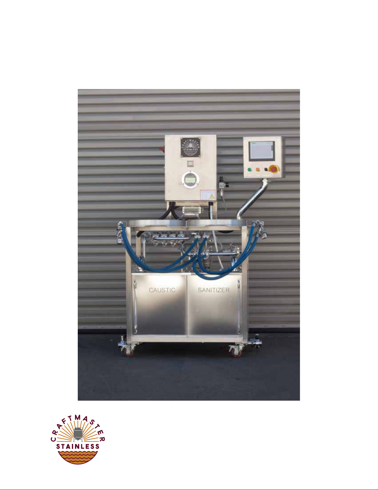
PARTS AND COMPONENTS
4
Main Control Panel
Main Power Switch
Omron Temperature Controller
Pressure Control Instrument
Solenoid Control Manifold
Keg Loading Platform
Caustic Reservoir
Reservoir Drainage Valve
Secondary Control Panel
Siemens Touch Screen
Emergency Stop
Inlet Pressure Regulator
Micromatic Keg Coupler
Sanitizer Reservoir
Sight Tube
1.
2.
3.
4.
5.
6.
7.
8.
9.
10.
11.
12.
13.
14.
15.
1
2
3
4
6
7
8
9
10
11
12
13
14
15
5
** VIDEOS AVAILABLE ON YOUTUBE **
5
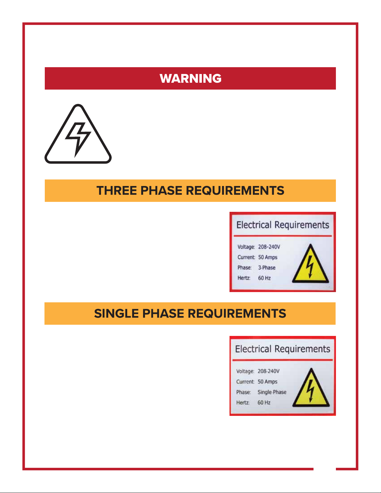
ELECTRICAL REQUIREMENTS
Electrical work presents significant risk to one's health
and safety. All electrical work should be performed
by a licensed professional.
Voltage :
Current :
Phase:
Hertz:
Plug Type:
208 - 240V
50 Amps
3 - Phase
60Hz
L15 - 30
Voltage :
Current :
Phase:
Hertz:
Plug Type:
208 - 240V
50 Amps
Single - Phase
60Hz
L6 - 30
** VIDEOS AVAILABLE ON YOUTUBE **
Table of contents


