manuals.online logo
Brands
  1. Home
  2. •
  3. Brands
  4. •
  5. Crown
  6. •
  7. Amplifier
  8. •
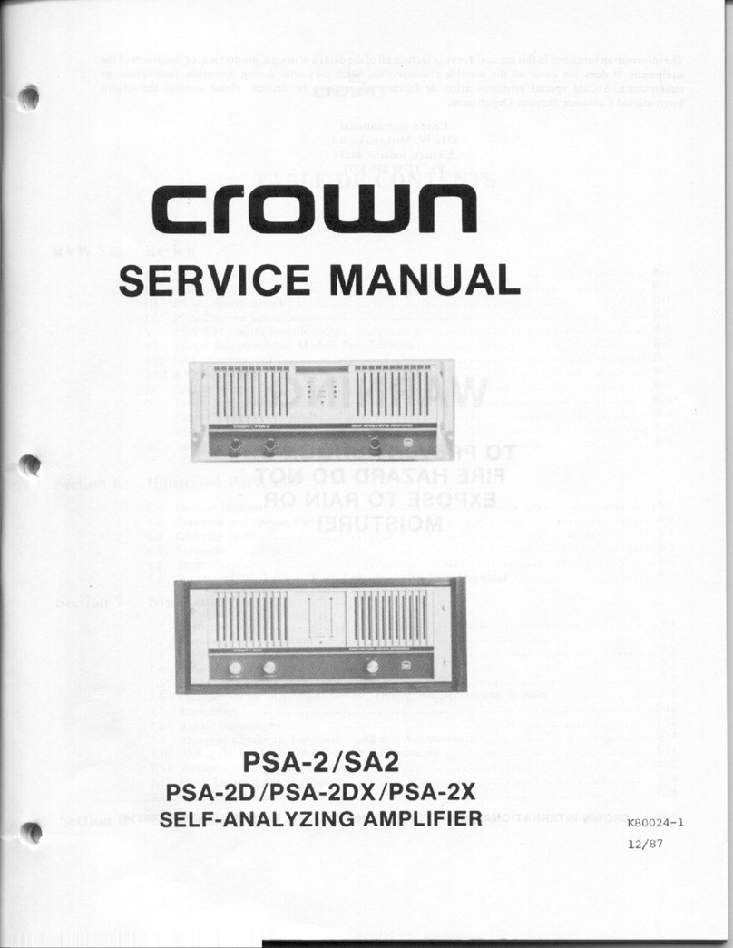
  9. Crown Studio Reference I Studio Reference II User manual

Crown Studio Reference I Studio Reference II User manual

This manual suits for next models

2

Other Crown Amplifier manuals

Crown VFX-2 User manual

Crown

Crown VFX-2 User manual

Crown CE-1000A Guide

Crown

Crown CE-1000A Guide

Crown I-Tech I-T5000 HD User manual

Crown

Crown I-Tech I-T5000 HD User manual

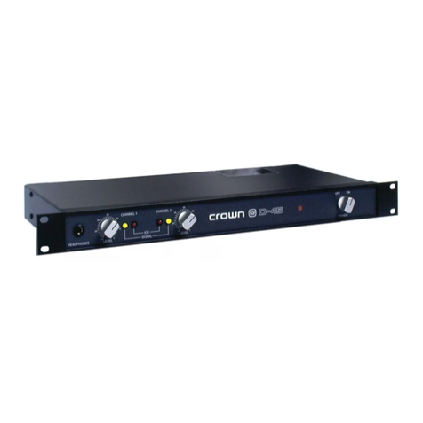
Crown D-45 User manual

Crown

Crown D-45 User manual

Crown PS-400 User manual

Crown

Crown PS-400 User manual

Crown PowerTech PT 3.1 User manual

Crown

Crown PowerTech PT 3.1 User manual

Crown Studio Reference I User manual

Crown

Crown Studio Reference I User manual

Crown D-60 User manual

Crown

Crown D-60 User manual

Crown ce 4000 User manual

Crown

Crown ce 4000 User manual

Crown CROWN K Series User manual

Crown

Crown CROWN K Series User manual

Crown Micro-Tech MT-2400 Manual

Crown

Crown Micro-Tech MT-2400 Manual

Crown VRACK User manual

Crown

Crown VRACK User manual

Crown Delta Omega DO-2000 User manual

Crown

Crown Delta Omega DO-2000 User manual

Crown Macro-Tech MA-2400 Quick start guide

Crown

Crown Macro-Tech MA-2400 Quick start guide

Crown 180MA Operator's manual

Crown

Crown 180MA Operator's manual

Crown 135MA User manual

Crown

Crown 135MA User manual

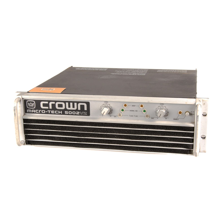
Crown Macro-Tech 5002 VZ User manual

Crown

Crown Macro-Tech 5002 VZ User manual

Crown XTi 1000 User manual

Crown

Crown XTi 1000 User manual

Crown DSi 2000 User manual

Crown

Crown DSi 2000 User manual

Crown SA-2 User manual

Crown

Crown SA-2 User manual

Crown XS500 User manual

Crown

Crown XS500 User manual

Crown PSA-2 User manual

Crown

Crown PSA-2 User manual

Crown ComTech DriveCore CT 475 User manual

Crown

Crown ComTech DriveCore CT 475 User manual

Crown 140MPA User manual

Crown

Crown 140MPA User manual

Popular Amplifier manuals by other brands

Magnat Audio EDITION FOUR Owner's manual/warranty document

Magnat Audio

Magnat Audio EDITION FOUR Owner's manual/warranty document

Inter-m PA-2000A Operation manual

Inter-m

Inter-m PA-2000A Operation manual

Yamaha TX6n owner's manual

Yamaha

Yamaha TX6n owner's manual

Peavey TNT 150 user guide

Peavey

Peavey TNT 150 user guide

Bosch LBB 1903/10 Installation and user instructions

Bosch

Bosch LBB 1903/10 Installation and user instructions

Avocent Emerge DA1200D Installer/user guide

Avocent

Avocent Emerge DA1200D Installer/user guide

Redgum RGi35 operating instructions

Redgum

Redgum RGi35 operating instructions

Cambridge Audio AXA25 user manual

Cambridge Audio

Cambridge Audio AXA25 user manual

Alpine MRP-M200 owner's manual

Alpine

Alpine MRP-M200 owner's manual

Technical Pro H1502UrBT user manual

Technical Pro

Technical Pro H1502UrBT user manual

FMS EMGZ307 operating manual

FMS

FMS EMGZ307 operating manual

Racal Instruments 5601 user manual

Racal Instruments

Racal Instruments 5601 user manual

Valcom V-1094A Technical specifications

Valcom

Valcom V-1094A Technical specifications

Cambridge Audio 851D user manual

Cambridge Audio

Cambridge Audio 851D user manual

QSC 3800 Specifications

QSC

QSC 3800 Specifications

NAD C300 owner's manual

NAD

NAD C300 owner's manual

Rotel RMB-1077 owner's manual

Rotel

Rotel RMB-1077 owner's manual

Peavey Monitor 300 Series operating guide

Peavey

Peavey Monitor 300 Series operating guide

manuals.online logo
manuals.online logoBrands
  • About & Mission
  • Contact us
  • Privacy Policy
  • Terms and Conditions

Copyright 2025 Manuals.Online. All Rights Reserved.

PROFESSIONAL
STUDlO
AMPLIFIERS
Studio
Referenc
dio
Referenee
Some
models
may
be
exported under
the
name
Asrr@rou@
O
"99
8by
Crown
Ir~ternatit:,nal,
fnc.,
P.O.
Box
t
COO,
Elkhart.
lndizn~i
46575-?OQO
U.S.A.
Telephone:
219-244-
8000.
Sfudio
Refere?-9c:cawplifiers
are
produced
by
Crawn
fnterrsaticsnal,
Inc,
xr'radernark
Notice:
Skrdio
Reference'*
and
Gronnd~d
&!.idge7"
are
tradcrnarks
and
Amcnm:'@
&IrcswsT
10C?
ODEP
IQ
S,ysl'cm.e"
and
&"i.PF
are
registered
trademarks
trf
Crcwn
BntsrnationaY,
Irx.
Blher
trademarks
are
the
properv
of
their
respeclive
owrwrs.
@Krawn"
--,,,
Stlidio
Refgrence
Service
Manual
, , ,
.-.
-""..."" R~K
6
*-....-
The
information
furnished
in
this
manual
does
not
Include
all
of
the
de"iaifs
sf
design,
production,
or
variations
of
the
equipment.
Nor
does
it
cover
every
possible
8itua"ii~n
which
may
ariss
during
installation,
operation
sr
maintenance.
if
you
need
special
assistance
beyond
the scope
of
this
manuas,
please
eontact
the
Crown
Technical
Suppart
Group,
Mai/:
P.0.
BQX
4008
Elkhart
lN
465?5-1000
Sbippin-ag:
Pit.
2
S,W,,
171
8
W,
Mishawaka
Rd.,
Elkhark
EN
4651
7
Phone:
$800)
342-6939/(2
1
9)
294-8206
FAX:
$2
"19)
294-8361
Web:
~w~cPQw~~u~~~~co~
TO
PREVEMT
ELECTRlC
SMOCK
80
NQT
REMOVE
TOP
OR
BQnDM
COMERS.
NQ
USER SERVICWBLE
.
PARTSINSIDE,
REFER
SERVOCtNC
TO
QUALIFIED
SERVICE
PERSOMNEL*
DISCONNECT
POWER
CORD
BEFORE
REMOVING
RmR
ENPUT
MODULE
TO
ACCESS
GAIN
SWITCH,
A
PR~VENIR
LE
CHOG
~LECTRIOUE
N'ENLEVU
PA8
LES
CQUVERTURES,
RlEM
DES
PART
lES
UTlLES
A
L"INT~RIEUR,
D~BRANCHER
u
BORNE
AVANT
DWUVRIR
U
MODULE
EN
ARRI~RE.
f
0
REDUCE
THE
RISK
OF
ELECTRIC
SHOCK,
DO
NOT
EXPOSE
THlS
EQUIPMENT
TO
RAIN
OR
MOISTURE!
Rev.
Q
12-98
Initial Printing
This
page
intentionally
left
blank
Rev
8
-
.
.-
Studio
Reference
Service
Manu3l
@crown
1
Bntroductisn
...................................................................................................
3-1
........................................................................
1.
1
The
Stndis
Referents
1-1
1.2
Scope
................................................................................................
1-1
............................
1.3
Warranty
.~.~~~~~...~.~..A~~~~~....,.........
1-1
2
Specifications
................................................................................................
-2-1
2
.
"Berformance
......................................................................................2.
1
2.2
Pswei
.................................................................................................
2-1
23
Cantrofs
.............................................................................................
2-2
2.
4
f
ndicators
..........................................................................................
2.2
......................................................................................
2.5
l~putsautput
2-3
2.6
Output
Signal
.....................................................................................
2-3
22
Protcctisn
..........................................................................................
2.3
2.8
Construction
......................................................................................
2.3
3
Va1tags
Conversion
........................................................................................
3-1
.................................................................................................
4
Circuit
Theory
4-4
...........................................................................................
4.1
Overview
4-1
4.2
Features
.............................................................................................
4-2
4.3
Frant
End
Operation
..........................................................................
4-2
4.3.1
Balanced
Gnin
Stage
(BGS)
.....................................................
4-2
4.3.2
Variable
Gain
Stage
(VGS)
........................................................
4-2
4.3.3
Error
Amp
..................................................................................
4.2
4.4
Voltage
Amplification
.........................................................................
4-2
4.4.1
Voltage
Transfators
....................................................................
4.3
..................................................
4.4.2
bast
Voltage
Amplifiers
(LVAS)
4-3
...............................................................
4.5
Grounded
Bridge
Topology
4-4
.........................................................................
4.5.
Wigh
Side
(HS)
-4-4
4.5.2
Law
Side
(LS)
............................................................................
4.4
....................................
4.6
Output
Device
Emulation
Prccalectian
(OBEP)
4-5
4.7
Ganliol
Circuitry
................................................................................
4-6
4.7.1
DC$LF
Protect
............................................................................
4-6
4.
7.2
fault
Circuit
...............................................................................
4-6
4.7.3
Turn
On
Belay
...........................................................................
4-6
................................................................................
4.7.
4
Fan
Corjtrol
4-6
4.8
Power
Supply
....................................................................................
4-6
4.8.
1
AC
kine
Fiiter
............................................................................
4-6
423.2
Soft
Start
...................................................................................
4-6
4.8.
3
Over
Voltage
Protection
............................................................
4-7
..............................................................................
4.9
Display
Circuitry
"4-7
............................................................................................
4.9.1
1QC
4-7
4"9+2
ODEP
........................................................................................
4.7
........................................................................
433
Signal
Indicafis~s
4.7
.......
...........................................................................................................
"
5
Electrical Checkout
and
Adjustment
Procedures
,,,
.......................................
5-1
51
General
Informatiow
...........................................................................
5-1
52
Standard
Initiat
Conditions
................................................................
5-1
53
DC
Offset
..........................................................................................
5-1
5.4
Output
Bias
Adjustmen$
....................................................................
5-1
55
OBEP
Voltage
Adjustment
.................................................................
5-1
5.6
AC
Pawer
Draw
.................................................................................
5-1
5.7
High
tine
Gutsue
................................................................................
5-1
5-8
Common
Mode
Wejects'sn
..................................................................
5-1
5.9
Voltage
Gain
......................................................................................
5-2
533
Level
Controls
.................................................................................
5-2
5.
1
1
Current
bimi
"r
....
...............................................................................
5-2
512
Slew
Rate
and
*a
OK
Square
Wave
....................................................
5-2
.
..........*<."...........................................................................
5
f
3
Crosstalk
5-3
5.
1-4
Output
Power
...................................................................................
5-9
5.1
5
Reactive Loads
................................................................................
5-3
5.
16
ODEP
Limiting
.................................................................................
5-4
5%
17
Mute
and
Turn-On
Delay
..................................................................
5-4
5.
18
Law
Frequency
Protection
...............................................................
5-4
5.
19
Signal
to
Noise
Ratia
.......................................................................
545
5.20
Intermadulation
Diskoflion
...............................................................
5-5
5.21
LED
Functions
.................................................................................
5-5
5.22
Display
Set-Up
................................................................................
5-5
5.23
Turn-On
Transients
...........................................................................
5-5
5.24
Turn-OM
Transiep-rts
..........................................................................
5-5
525
Past
Testing
.....................................................................................
5-5
6
Schematics
....................................................................................................
6-1
7
Parts
Information
............................................................................................
7-1
7.
1
General
lnfarmation
...........................................................................
7-1
7.2
Standard
and
Special
Parts
...............................................................
7-1
7.3
Ordering
Parts
...................................................................................
7-1
........................................................
....................
7.4
Shipment
.....,.
7-1
7.5
Terms
.................................................................................................
7-7
..
7.6
Illustrated
Parts
List
.......................
.,
,.,,
................................
7-1
.........................
...................
Figure
7.1
Front
Panel
Exploded
View
,..
7-2
......................................
Figure
7.2
Top
Main
Assembly
Exploded
View
7-4
Figure
7.3
Bottom
Main
Assembly
Exploded
View
................................
7-6
Figure
7.
4
Back
Pans[
Assembly
Exploded
View
.......
.,
........................
7-8
Fi%jure
7.5
Output
Assembly
Exploded
View
.......................................
3-1
61
Figt,i
re
7%
Capacitor
Assembly
Exploded
View
...................................
7-12?
Figure
7.
7
PIP
Cage
Assembly
Exploded
View
...................................
7-15
R@K
0
.
-..,
_____ylll~1~1111__
.
, ,
Stvd8"~
Reference
Service
Manuai
@CrQWne
P,
,,
P
.................................................
8
Module
information
........................................................................................
8-4
8.1
General
information
...........................................................................
8-4
8.2
Studia
Reference
1
Module
lnfsrmatisn
.............................................
8-1
............................................
8.3
Studio
Reference
If
Module
Infsrmatisn
8-1
8-4
Q.4397
1-6
Main
Module
........................
...
..
,
..................................
$3-2
85
Q43369-0
Outp&r"lodeelie
..................................................................
8-8
8.6
Q43183A3
Control
Module
..............................................................
8-11
8.7
Q43.450-8
Control
Module
...............................................................
8-14
8.8
843584-2
Control
Module
...............................................................
8-17
8.9
a4301
8-3
Display
Modu8e
...............................................................
8-20
8.1
Q
64331
1-2
Main
Module
.................................................................
8-23
.............
8.1
1
Q43388-0
Main
Module
...................
....
..,,..
,.,
8-28
8.
t
2
Q43389-8
Butput Module
..............................................................
8-33
8.13
a4331
2-0
Display
Module
.............................................................
8-36
@crowne
P
-.."..
.......-
, , , ,
Studio
Reference
Service
pw
Manusf
R~K
0
P
P
Figure
2.1
Studio
Wefsrence
Dimensions
.........................................................
2-3
Figuss
3.1
Specific
Voltage
Wiring
...................................................................
3-1
Figure
32
Circuit
Breaker Selection
......
.............,...
......................................
3-11
Figure
4
.
t
Simplified
Studio
Refereilea
Biock
Diagram
...................................
4-1
Figure
4.2
Simplified
Ampiitier
Front
End
and
Voltage
Ampiifiication
Stages
..
4-3
Figure
43
Simpfified
Grounded
Bridge
...................
,.....
..............................
4-5
Figure
5.
1
Differentiatar
Circuit
........................................................................
5-2
figure
5-2
Differentiated
Square
Wave
..............................
..,,,,..*+.+'.........
5-2
................................................
Figure
53
10
kHz
Square
Wave
...................
...
5-2
Figure
5.
4
inductive
Load
CoId
........................................................................
5-3
Figure
5.
5
5~nd~etive
Load
Warm
......................................................................
5-3
Figure
56
Tartup@
Yest
Waveform
.....................................................................
5-4
Figure
5-4
OBEP
Limiting
Waveform
.....................................................................
5-4
Figure
7.
1
Front
Panel
Parts
.............................................................................
7-2
Figure
4.
2Top
Main
Assembly
Parts
................................................................
7-4
Figure
7.3
Bottom
Main
Assembly
Parts
.......................
..................................
7-6
........................
....................
Figure
7.
4
Back
Panel
Assembly
Parts
.........
7-8
...................
........................................
Figure
75
Output
Assembly
Par&
,.
7-16
Figure
73
Capacitor
Asssmbly
Parts
............................................................
F.12
Figure
72
PIP
Cage Assembly Parts
.............................................................
7-14
Figure
8.
1
a43371
-6
Main
Msdule
Map
..........................................................
8-7
Figure
8.2
Q43363-8
Output
Module
Map
.....................................................
8-18
Figure
823
Q43383A3
Control
Maduis
Map
....................................................
8-13
Figure
8.4
Q843458-8
Control
Madula
Map
.....................................................
8-16
Figuse
825
Q4J5Q4-2
Control
Module
Map
.....................................................
8-19
Figuw
8.
6
64381
8-3
Bispray
Module
Map
.....................................................
8-22
Figure8.7
a4336
1-2
Main
Module
Mag
....................
......
..............................
8-27
figure
8.8
843388-0
Main
Module
Map
........................................................
8-32
Figure 83
043389-8
Output
Modube
Map
.....................................................
8-35
Figurs
8'16
Q43312-0
Display
Msduls
Map
..................................................
8-38
t
.I
Ths
Studia
Referenee
The
Studio
Reference
amplifiers
are
the
flagship
sf
Crown
Internatfsna\.
They oRsr
the
best
in
sound
re-
production
with
a
dynamic
range
capable
of
accurately
reproducing
20-bit
digital
recardings.
Super
low
har-
monic
and
intermodulation
dis$or$ion
provides
the
best
transfer
function in
the
business.
And
the
ultra-high
damping
factor
af
20,000
detivsrs
superior
foud-
speaker
motion
control
for
a
tight
and
clean
low-end.
1.2
Scape
This
massr_eaI
contains
sewice
information
for
the
Grown
Studio
Reference
power
amplifiers..
It
ia
designed
I~P
be used
with
the
appilcable
Reference
Manual'
How-
ever,
some
important
information
is
duplicated
in
this
Servica
Manual
in
case
the
Reference
Manual
is
not
readily
availabls.
This
Service
Manual
includes
severaB
sections,
These
sectiians
include
Sp~cifications,
Vottag~
Conversion,
Circuit
Thssry?
EEfectrieal
Che~kout,
Parts
Information,
Module
Information,
aod
Exploded
View
Drawings,
Schematics
are
included.
Note
that
a
Mexdu%e
is
com-
prised
a$
the
circuit
board
with
the
component
parts
instal!@d.
Crown
does
not
sell
blank
(unpopulated)
cis=.
cuiQ
boards.
CAUTIOH:
TRs
infermatien
in
this
manual
Is
Intsndsd
to
b~
ossd
by
an
exparlenc%d
t@~hnlclaa
only
h
1.3
Warranty
Each
Reference
Manual
contains
basic
pslieies
as
re-
fated
to
%he
customer.
In
addition,
it
should
be
staked
that
this
ssrviee
dacumentalisn
is
meant
ts
be
used
snl
y
by
properly
trained
service
personnel.
Because
most
Crawn
products
carry
a
3
Year
Full
Warranty
(in-
ciud~ng
round
trip
shipping
within
the
United
States),
aft
warranty
service
should
be
referred
to
the
Crown
Factory
or
Authorized
Warran&
Sewice
Center.
See
the
applicablsOwner's
Manual
for
warranty
details,
To
find
the
iocation
QI
the
nEarsst
Authorired
Sarvice
Center,
or
to
obtain
instructions
fcar
receiving
Crown
Factory
Service,
piease
contact
tho
Crown
Technical
Support
Group
(within
North
Amerrca)
or
your
Crown/Amcrg;bn
Importgr
(outside
North
America),
Plant
2
S.W,
171
8
W.
Mishawaka
Bd,
Elkhaa,
IN
USA
4651
'7
Phone:
(21
9) 294-8200
Tall
Free:
(8QO)
M2-6939
FM:
(21
9)
294-8301
Web:
.er~wnaudis~com
Introduction
t
-7
Sf
~dio
Reference
Service
Manual
This
pa@@
intentionally
left
blank
introduction
4
-2