Crown CT20101-18 User manual


2
Content / Sommaire / Contenido / Índice / İçindekiler / Содержание / Зміст /
Мазмұны /
English
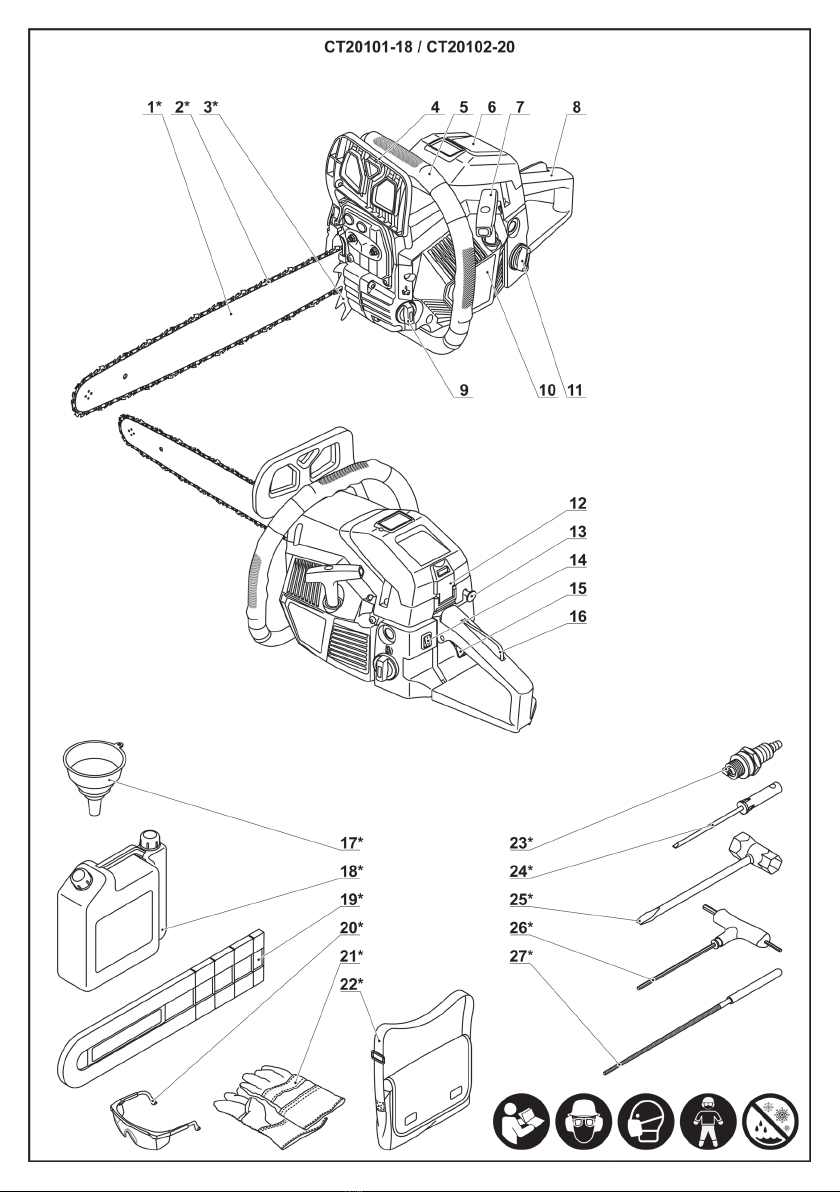
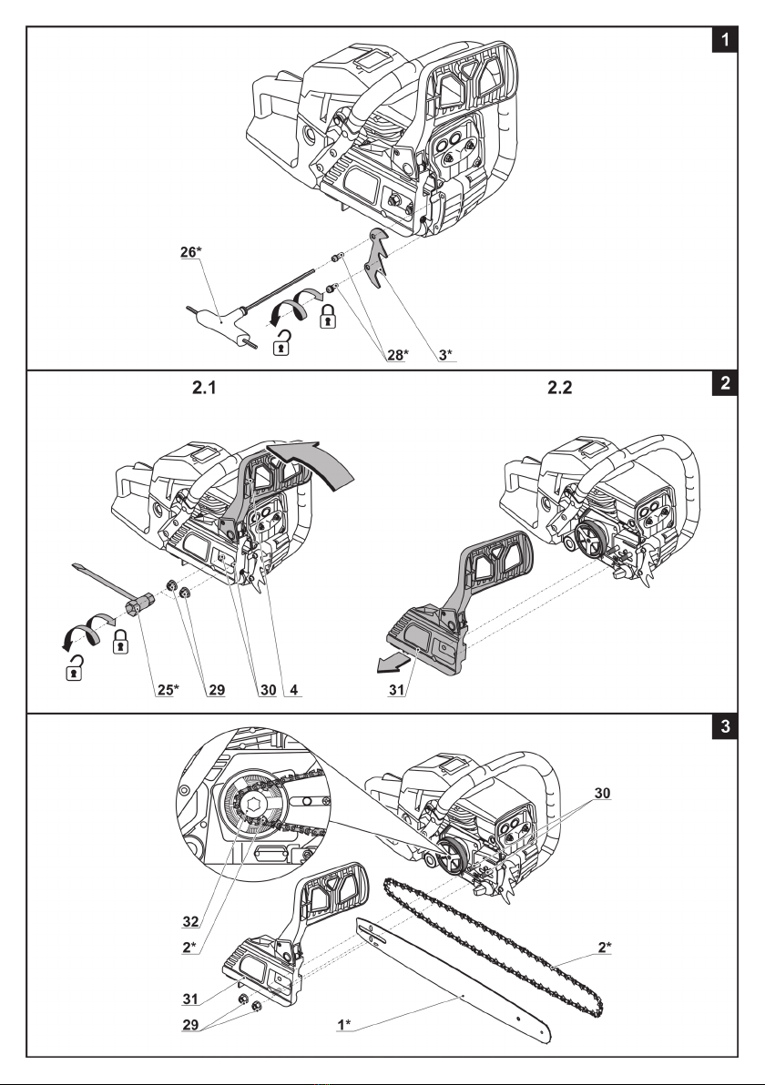
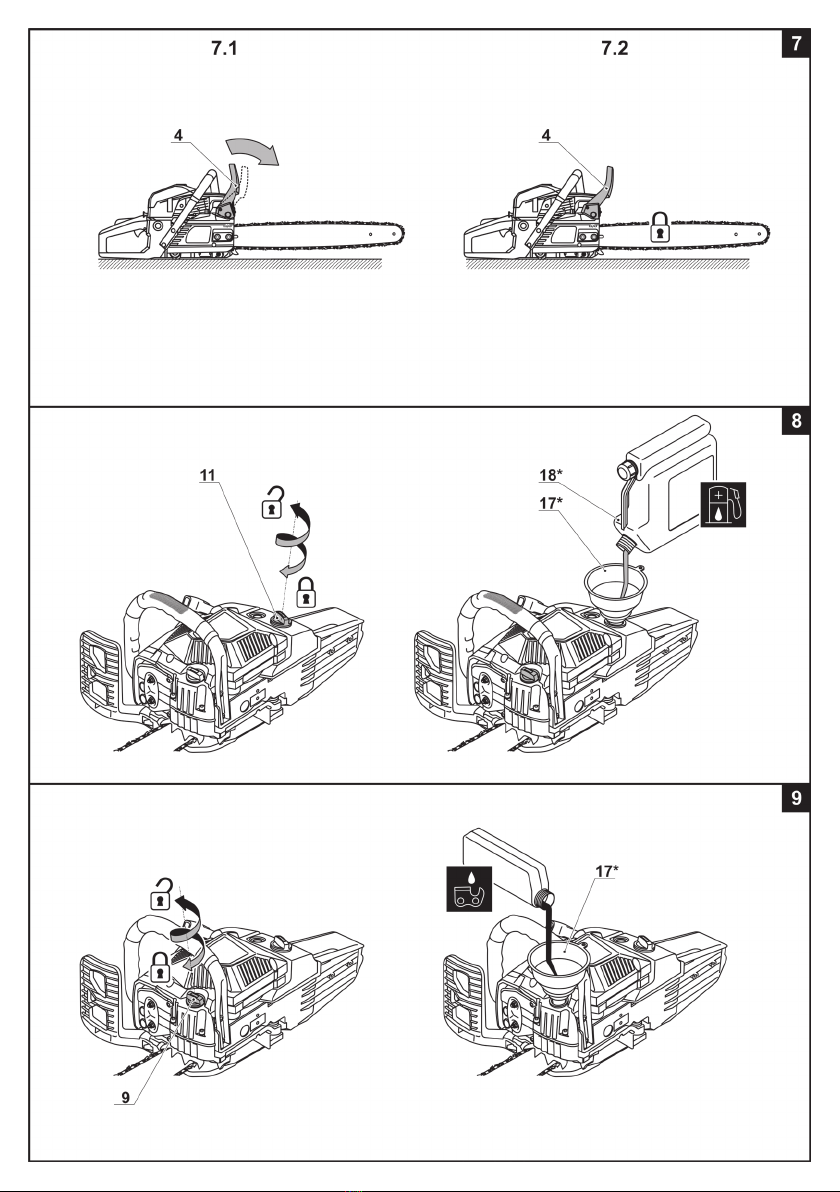
Explanatory drawings �������������������������������������������������������������������������������������������������������������pages
General safety rules, instructions manual ����������������������������������������������������������������������������� pages
CROWN warranty �������������������������������������������������������������������������������������������������������������������� page
Warranty card and service cards ������������������������������������������������������������������������������������������� pages
4 - 11
12 - 21
118
136 - 138
Français
Dessins explicatifs ������������������������������������������������������������������������������������������������������������������ pages
Recommandations générales de sécurité, mode d'emploi ���������������������������������������������������� pages
Garantie CROWN �������������������������������������������������������������������������������������������������������������������� page
Garantie coupon et cartes de service ������������������������������������������������������������������������������������ pages
4 - 11
22 - 32
119
136 - 138
Español
Dibujos explicativos ������������������������������������������������������������������������������������������������������������ páginas
Recomendaciones generales de seguridad, manual de instrucciones ������������������������������ páginas
Garantía CROWN ����������������������������������������������������������������������������������������������������������������� página
Tarjetas de mantenimiento y cupón de garantía ����������������������������������������������������������������� páginas
4 - 11
33 - 43
120
136 - 138
Português
Esboços explicativos ���������������������������������������������������������������������������������������������������������� páginas
Recomendações gerais de segurança, manual de instruções ������������������������������������������� páginas
Garantia CROWN ����������������������������������������������������������������������������������������������������������������� página
Cupão da garantia e cartões de reparação ������������������������������������������������������������������������ páginas
4 - 11
44 - 54
121
136 - 138
Türkçe
Açıklayıcı resimler �������������������������������������������������������������������������������������������������������������� sayfalar
Genel güvenlik tavsiyeleri, kullanım kılavuzu ��������������������������������������������������������������������� sayfalar
CROWN garanti koşulları ������������������������������������������������������������������������������������������������������� sayfa
Garanti kuponu ve servis kartları ���������������������������������������������������������������������������������������� sayfalar
4 - 11
55 - 64
122
136 - 138
Русский
Пояснительные рисунки �������������������������������������������������������������������������������������������������страницы
Общие указания по ТБ, инструкция по эксплуатации ������������������������������������������������� страницы
Гарантия CROWN ���������������������������������������������������������������������������������������������������������� страница
Гарантийный талон и сервисные талоны �������������������������������������������������������������������� страницы
4 - 11
65 - 75
123
136 - 138
Украïнська
Пояснювальні малюнки ���������������������������������������������������������������������������������������������������� сторінки
Загальні вказівки по ТБ, iнструкція з експлуатації ��������������������������������������������������������� сторінки
Гарантія CROWN ������������������������������������������������������������������������������������������������������������� сторінки
Гарантійний талон i сервісні талони �������������������������������������������������������������������������������� сторінки
4 - 11
76 - 86
124 - 128
136 - 138

3
Content / Sommaire / Contenido / Índice / İçindekiler / Содержание / Зміст /
Мазмұны /
Қазақ тілі
Түсіндіргіш әлеміштер ���������������������������������������������������������������������������������������������������������беттер
Жалпы қауіпсіздік жөніндегі ұсыныстар, пайдалану нұсқаулығы ���������������������������������������� беттер
CROWN кепілдігі ���������������������������������������������������������������������������������������������������������������������� бет
Гарантиялы талон және қызмет көрсету карталары ���������������������������������������������������������беттер
4 - 11
87 - 97
129
136 - 138
�����������������������������������������������������������������������������������������������������������������������������
����������������������������������������������������������������������������������������������������
�����������������������������������������������������������������������������������������������������������������������
�����������������������������������������������������������������������������������������������������������
4 - 11
98 - 107
130
136 - 138
��������������������������������������������������������������������������������������������������������������������������
��������������������������������������������������������������������������������������������
��������������������������������������������������������������������������������������������������������������������
�����������������������������������������������������������������������������������������������������������
4 - 11
108 - 117
131
136 - 138

4

5

6

7

8

9

10

11

12
English
Tool specications
Gasoline chain saw CT20101-18 CT20102-20
Tool code 420893 420909
Power output [W] 1800 2300
Idling speed (with assembled cutting unit) [min-1]3000±250 3000±250
Saw chain speed (by engine power 100% / 133%) [m/s] 15,8 / 21 18,3 / 24,3
Engine technical data:
- engine displacement [cm3]45 54,6
- number of cylinders 1 1
- number of strokes / type of cooling two-stroke / air cooling two-stroke / air cooling
Fuel tank capacity [l] 0,55 0,55
Fuel used oil:petrol -
1:25 oil:petrol -
1:25
Oil tank capacity (for lubricate the saw chain) [l] 0,26 0,26
Guide bar length [mm]
[inches] 450
18" 500
20"
Saw chain parameters (chain pitch / chain gauge) [mm]
[inches] 8,26 / 1,47
0�325" / 0�058" 9,3 / 1,47
3/8" / 0�058"
Weight (excluded cutting unit) [kg]
[lb] 5,54
12�21 5,58
12�3
Sound pressure [dB(A)] 98 98
Acoustic power [dB(A)] 110 110
Weighted vibration [m/s2]6,8 6,8

13
English
Noise information
Always wear ear protection if the sound
pressure exceed 85 dB(A).
Declaration of conformity
We declare under our sole responsibility that
this product is in conformity with the regulations
2006/42/EC, 2004/108/EC, 2005/88/EC�
Certication Wu Cunzhen
manager
Merit Link International AG
Stabio, Switzerland, 04.07.2017
General safety recommendations
CAUTION! Make sure you have read and
understood all the recommendations.
Failure to observe the following
recommendations may cause re and /
or serious injuries.
•Do not operate this tool when tired, ill, or under the
inuence of alcohol, drugs, or medication.
•Children and teens under the age of 15 must not use
the tool, except for teens guided by an adult�
•Inspect the tool before use. Replace all damaged
parts. Check for fuel leaks. Make sure all fasteners are
in place and secure� Any failure could cause personal
injury to the operator and bystanders, as well as
damage to the tool�
•Be aware of the risk of injury to the head, the hands
and the feet�
•Do not allow children and unauthorised persons near
places where operations with the use of the tool are
carried out� Third parties may distract the operator's
attention, and he may loose control over the tool�
Safety warnings for petrol tools
WARNING: Gasoline is toxic, highly
ammable, and its vapours can explode
if ignited.
Take the following precautions:
•do not smoke, keep sparks and open ames from
the area while adding fuel or operating the tool;
•store fuel only in containers specically designed
and approved for the storage of such materials;
•avoid creating a source of ignition for spilled fuel�
Do not start the engine until the fuel vapours dissipate;
•always stop the engine and allow it to cool before
lling the fuel tank. Never remove the cap of the fuel
tank, or add fuel, when the engine is hot;
•never operate the tool without the fuel cap
securely in place. Loosen the fuel tank cap slowly to
relieve any pressure in the tank;
•mix and add fuel in a clean, well-ventilated area or
outdoors where there are no sparks or ames;
•move the tool at least 3m from the fuelling source
and site before starting the engine;
•do not position ammable or nylon / fabric objects
near and / or on the tool;
•close the fuel tank plug tightly to avoid leakages
of fuel and escape of fuel's vapors;
•if in the process of fueling the tool you have
spilled fuel or oil on it, carefully wipe the tool;
•if in the process of fueling the tool you have
spilled fuel or oil on yourself, change your clothes
and carefully wash parts of your body in contact with
the fuel or oil, using water with soap�
Safety regulations during the preparatory
operations
•Breathing exhaust fumes can be lethal� Operate
this tool only in a well ventilated area and never in
places affected by dust, acids, vapours, explosive or
ammable gases.
•Use personal protection equipment� Always wear
protective goggles� When necessary, use respirators,
non-slipping boots, hard hats and earplugs� Long
sleeve shirts are recommended� The use of personal
protection equipment is one of the factors that reduce
the risk of injuries.
•Do not wear loose clothing, jewellery, short pants,
sandals or go barefoot� Hair, garment parts and gloves
should be protected against contact with the moving
parts of the tool�
•Use the tool only in daylight or good articial light.
•Avoid accidental starting� Do not apply excessive
force, take a stable position and always try to keep
balance this will facilitate control over the tool�
•Stop and switch the engine to off for maintenance,
repair, or for changing parts�
•Do not use parts, accessories or attachments which
are not authorised for this tool� Doing so could lead to
serious injury to the user, or damage to the tool, and
void your warranty�
•To reduce a re hazard, replace the faulty mufer
and spark arrestor, keep the engine and mufer free
from grass, leaves, excessive grease or carbon build
up�
Safety regulations for using the tool
•Stop the engine immediately if you feel an excessive
vibration. Vibration is a sign of trouble. Inspect
thoroughly for loose nuts, bolts or damage before
continuing� Repair or replace all affected parts as
necessary�
•Tools are to be used only in operations, for which
they have been designed, which will ensure safety and
help achieve better results�
•Keep hands, face, and feet at a distance from all
moving parts�
•Do not touch the engine or mufer. These parts get
extremely hot from operation� When turned off they
remain hot for a short time�
•Always stop the engine while taking a break.
•If you strike or become entangled with a foreign
object, stop the engine immediately and check for
damage� Do not operate before repairing the damage�
Do not operate the tool with loose or damaged parts�
Service of the tool
•Keep the tool clean. Never clean the tool with
ammable liquids or solvents.
•Your tool should be serviced only by qualied
specialists, with the use of recommended spare parts�

14
English
This will guarantee labour safety, when your tool is
being applied�
Safety regulations after using the tool
•Never store the tool, with fuel in the tank, inside a
building where fumes may reach an open ame or
spark.
•Allow the engine to cool before storing or transporting�
Be sure to secure the tool while transporting�
•Always use the handle to move or transport the tool�
•The tool should be stored in dry place, out of
children's reach� Do not allow use of the tool by persons
who have not read this manual and are inexperienced�
In the hands of an unqualied person, the tool may be
dangerous both for the operator and his environment�
•Never douse or squirt the tool with water or any
other liquid�
•Spent oil (lubricated models) and condensate must
be disposed of in accordance with environmental
protection regulations and the current legislation�
•Save these instructions� Refer to them often and use
them to instruct other users. If you loan someone this
tool, also loan them these instructions as well�
Safety guidelines during tool operation
Specic safety rules for the tools equipped with
petrol engine
Attention! Non-observance of the below
listed rules may become a cause of re,
serious injuries or even death of the
user. Always keep nearby a medical rst-
aid kit as well as re ghting means (re
extinguisher, spade, etc.).
•When in operation, the tool's ignition system
generates electromagnetic impulses that may interfere
with the work of electronic heart pacemakers, so
consult a doctor before staring to use the tool�
•During operation of this tool, there are harmful
substances (fuel vapors, exhaust gases containing
carbon monoxide, etc�) emitted inhaling of which may
negatively inuence the operator's health. Refuel the
tool or operate it only if there is enough ventilation
available�
Before commencing operation
•The tool shall be operated only by a person properly
acquainted with the use and maintenance and able to
demonstrate the ability to operate it properly�
•Using the tool by children or teenagers is expressly
prohibited�
•Do not operate the tool in bad weather, thick fog,
strong wind, rain and snow create additional hazards
during the operation of the tool (falling on slippery
ground, unpredictable direction of the tree fall etc�)�
•Prior to operating the tool, inspect the worksite,
remove any interfering objects (branches, rocks etc.),
and plan escape routes in the event of danger� Be
especially careful when working on slopes.
•Do not make any modications to the tool and do not
use a defective tool, as it can increase the operation
safety risk.
•Use only sharp, defect-free saw chains� Prior to
operating the tool, make sure that the saw chain has
been properly tensioned and the chain lubrication
system is functioning adequately�
•Use the tool only for sawing wood� Sawing other
materials may result in damage to the tool (in this case,
the warranty repair right is voided)�
•Remove all nails or any other metal objects from
blanks before cutting.
•Never operate the tool with dismantled protectors.
Damaged protectors must be replaced immediately�
Under no circumstances should you use a tool that
is not adequately equipped or has been subjected to
unauthorized modication.
•Prior to starting the tool, make sure that the saw
chain does not contact any other objects�
The operator or the tool's owner shall
be liable for the possible accidents or
damage that may be caused to a third
persons or their property.
During operation
•Do not operate the tool in the rain nor leave it in
the rain�
•Always use means of individual protection: glasses
or face shield, ear protectors, dense texture clothes,
rugged footwear with non-slip soles. Never work in
shorts or open footwear� A protective helmet must be
worn when felling trees or cutting branches�
•The presence of other persons or animals on the
worksite is prohibited.
•Never start sawing until the saw chain develops full
speed�
•Preserve stable position during the work and hold
the tool with both hands� Don't allow the handles to
become oily and never operate the tool with one hand�
•Do not operate the tool above shoulder level, when
standing on a ladder, or when sitting in a tree�
•Always process only one blank - this is the only way
to x it properly.
•If the saw chain is blocked in the cut during the
operation of the tool, turn off the tool immediately and
only then eliminate the cause of the saw chain block.
•Do not allow the tool to get overheated when in
prolonged use�
•Beware of the recoil (sudden back jerk of the tool)
that may be caused by violations of the operating
instructions (twisting or blocking of the cutting unit
in the cut)� To reduce the effects of recoil, use the
following precautions:
•try not to twist the tool relative to the workpiece
surface during the tool's operation;
•always hold both handles of the tool with both
hands, this will help you maintain the necessary
control over the tool;
•do not stand in the plane of the cutting unit;
•use only a well sharpened and properly tensioned
saw chain;
•never saw with the end of the cutting unit, as
in this case, the probability of creating a recoil is
maximum;
•use a spiked bumper kit 3as a lever whenever
possible (see g. 12.2);
•do not try to place a moving saw chain into the
previous cut;
•observe the rules for sawing, especially when
cutting tree trunks or branches under load.
After nishing operation
•It is allowed to remove the tool from the working
place only after shutting down the engine and full
stopping of the saw chain�

15
English
•Certain elements of the tool (for example, cutting
unit, parts of the engine, etc�) get very hot during
operation - don't touch them before they cool down�
•Keep the tool in a place protected from moisture
and not accessible for children, always remove the cap
from the spark plug.
•If you plan not to use the tool for a long time, be
sure to drain the oil and fuel tank of and to remove
the chain blade and the saw chain and store them
wrapped in oiled paper�
Symbols used in the manual
Following symbols are used in the operation
manual, please remember their meanings� Correct
interpretation of the symbols will allow correct and safe
use of the tool�
Symbol Meaning
Serial number sticker:
CT ��� - model;
XX - date of manufacture;
XXXXXXX - serial number�
Read all safety regulations
and instructions�
Wear:
•helmet;
•safety goggles;
•ear protectors�
Wear a dust mask.
Wear dense texture clothes
and rugged footwear with
non-slip soles�
Do not work in rain or snow.
Movement direction�
Rotation direction�
Locked.
Unlocked.
Symbol Meaning
Prohibited�
Increase / decrease the
chain tension�
Increase / decrease in the
quantity of chain lubrication�
Adding fuel mixture�
Adding oil for lubricating of
the saw chain�
It is forbidden to be in the
danger zone.
Always hold both handles of
the tool with both hands�
Never operate the tool with
one hand�
Beware of the kickback.
Attention. Important.
A sign certifying that the
product complies with es-
sential requirements of the
EU directives and harmo-
nized EU standards.
Useful information�
Wear protective gloves�

16
English
Symbol Meaning
Do not dispose of the tool in
a domestic waste container�
Tool designation
The tool is designed to saw pieces of wood (logs,
planks, branches) and may also be used for tree
felling. It is suitable for both the transverse and
longitudinal cutting of timber. Petrol engine makes
them mobile (no need to connect them to electric
network).
The tool is designed for right-handed users only�
Tool components
1 Guide bar *
2 Saw chain *
3 Spiked bumper kit *
4 Brake guard
5 Front handle
6 Cap
7 Starter cord
8 Handle
9 Oil tank plug
10 Starter cover
11 Fuel tank plug
12 Latch
13 Air throttle control lever
14 On / off switch
15 Throttle trigger
16 Throttle interlock
17 Funnel *
18 Container for preparation of fuel mixture *
19 Protective guard of the cutting unit *
20 Google *
21 Gloves *
22 Tool bag *
23 Spark plug *
24 Screwdriver *
25 Multi-purpose wrench *
26 Special wrench (3 x Allen key) *
27 Round le *
28 Screw of the spiked bumper kit *
29 Nut
30 Pin
31 Guide bar cover
32 Drive gear
33 Saw chain tension screw
34 Adjusting screw
35 Template *
36 Flat le *
37 Screw "T" for adjusting idle speed
38 Screw "L" for to adjusting low speed
39 Screw "H" for adjusting high speed
40 Special nut *
41 Cover of the air lter
42 Air lter *
43 Spark plug cap
* Optional extra
Not all of the accessories illustrated or described
are included as standard delivery.
Installation and regulation of tool elements
Switch off the tool before fullling all procedures.
Do not draw up the fastening elements
too tight to avoid damaging the thread.
Mounting / dismounting / setting-up of
some elements is the same for all tool
models, in this case specic models are
not indicated in the illustration.
Assembly / disassembly of the spiked bumper kit
(see g. 1)
•Put the tool on at ground.
•Install spiked bumper kit 3and screw the screw 28
with the help of the special wrench 26 (see g. 1).
•When disassembling the spiked bumper kit 3, repeat
the above operations in reverse order�
Assembly / disassembly of the cutting unit,
tensioning of the saw chain (see g. 2-4)
When used for extended periods of time,
guide bar 1 and saw chain 2 can become
very hot, therefore, you must wear pro-
tective gloves during assembly opera-
tions. This will also reduce the risk of injury from
the cutting edge of saw chain.
•Put the tool on at ground.
•Unscrew the nuts 29 with the help of the multi-
purpose wrench 25 (see g. 2.1).
•Move brake guard 4into the rearmost position and
remove guide bar cover 31 (see g. 2.1-2.2).
•Install guide bar 1 (see g. 3) and move it into
the direction of drive gear 32 (this will facilitate the
installation of saw chain 2)�
•Wrap saw chain 2around drive gear 32, then, place
the drive teeth of saw chain 2into the slot of the guide
bar 1� Note: saw chain 2 is installed correctly when
the cutting edges are facing forward.
•Install guide bar cover 31 (the tension pin must fall
into the hole in guide bar 1)�
•Screw nuts 29 onto pins 30 and tighten them slightly
by hand�
•Adjust the tension of saw chain 2� Holding the
front of guide bar 1 (see g. 4.1), rotate chain tension
screw 33 with a screwdriver (see g. 4.2). To increase
the tension of saw chain 2, turn chain tension screw 33
to the right, turn it left to reduce the tension�
•Pull saw chain 2until it abuts closely to the bottom
of guide bar 1�
•Continue to hold the front of guide bar 1while
tightening nuts 29 with multi-purpose wrench 25�
•When disassembling the cutting unit, repeat the
above operations in reverse order�
Saw chain tension checking (see g. 5)
Prior to each use of the tool and by
operation it is necessary to perform a
check, and if necessary, to adjust the
tension of the saw chain 2.
When operating saw chain 2, consider the following
factors:

17
English
•saw chain 2must always be properly tensioned,
and its lubrication system must function properly;
•new saw chain 2stretches more, inspection and
tension adjusting operations must be carried out
more frequently;
•during operation, saw chain 2gets heated and
lengthens, it shortens during cooling, consider this
factor when adjusting the chain tension: do not
adjust saw chain 2when it is hot�
The following are the indicators of a correctly tensioned
saw chain:
•pull saw chain 2from the center of guide bar 1
lightly and release. If saw chain 2is tensioned
correctly, the maximum distance between the pulled
saw chain 2and guide bar 1 is 3-4 mm (see g. 5.1);
•a properly tensioned saw chain 2should not sag
(see g. 5.2);
•a properly tensioned saw chain 2must move
freely around guide bar 1when pulled by hand (use
protective gloves when doing this, see g. 5.3). If
it does not, loosen the tension of saw chain 2, as
described above�
Saw chain lubrication system functioning check
(see g. 6)
The operation of the lubrication system of saw chain 2
can be checked as follows:
•run the tool engine and keep the end of the cutting
unit above a piece of cardboard or paper laid on the
ground;
•Note: Do not touch the ground with the chain,
maintain a distance of about 200 mm. If the above
results in the appearance of increasing traces of oil
on cardboard or paper, the chain lubrication system is
working properly. If, despite the oil tank being full, no
oil traces appear, contact the CROWN service center�
The amount of oil that lubricates saw chain 2can
be adjusted with the help of screw 34 (see g. 6). To
increase the volume of oil ow to the chain, rotate
adjusting screw 34 to the left, rotate it to the right to
reduce the oil ow.
The saw chain brake functioning check (see g. 7)
The saw chain brake must be activated at the recoil
of the tool. To check the functionality of the saw chain
brake, perform the following steps.
•Run the tool engine (as described below), place
it on the ground so that saw chain 2is out of contact
with the ground or with any other objects� Hold both
handles of the tool, start with full power (saw chain 2
begins moving). Press brake guard 4with your left hand
to move it forward (see g. 7) - saw chain 2must stop
immediately�
•If the saw chain brake does not function as described
above, contact the CROWN service center�
Do not operate the tool if the saw chain
brake is damaged.
Always keep in mind that even a
properly operating chain brake
may not provide protection in some
cases (for example, if the operator
falls or in the event of tree felling, when the cutting
unit plane is parallel to the ground etc.).
Initial operating of the tool
Mandatory check
Prior to commencing the work, be sure to check the
following:
•correctness of mounting and reliability of xing of all
elements of the tool;
•absence of damages to the elements of the tool;
•absence of fuel leaks;
•saw chain tension;
•correct operation of the saw chain lubrication
system;
•correct operation of the saw chain brake.
Information on the fuel mixture and oil to lubricate
the saw chain
Fuel for the two-stroke engine of the tool
is a mixture of petrol (octane number
of not less than 89RON) with special
motor oil in a proportion specied in the
engineering data sheet.
•Do not use other kind of oil (for example, motor oil
for four-stroke engines or oil for two-stroke engines of
motor boats)�
•Always precisely measure out the volume of the fuel
mixture's components - even a small inaccuracy may
lead to incorrect operation of the engine�
•It is expressly prohibited to use other fuel
mixtures as well as petrol alone for fueling of the
tool�
•Do not use the fuel mixture that has been stored for
more than a month�
Use only special oil to lubricate the saw
chain.
•Do not use other sorts of oil (e�g�, engine oil for four-
stroke engines etc.).
•Don not use waste oil under any circumstances�
•Note that , some sorts of oil thicken at a temperature
of 0°C and below, which may result in the incorrect
operation of the saw chain lubrication system or
damage to the tool� Follow the recommendations on
the oil used to lubricate the saw chain�
Non-observance of these rules may lead
to breaking of the engine and deprive
you of the right to warranty repair.
Preparation of the fuel mixture
•Prepare the fuel mixture in container 18� Pour into
container 18 a required quantity of petrol and then
add a required quantity of oil (see the graduations on
container 18), rmly tighten up the plug and mix (shake
up) the obtained mixture�
•Once again shake the container with the fuel mixture
before pouring the latter into the fuel tank.
Fueling of the tool (see g. 8)
•Clean the surface around the plug 11 and unscrew
it (see g. 8).

18
English
•Carefully pour the fuel mixture into the ller neck of
fuel tank. It is recommended to use a funnel 17 for this�
•Firmly tighten up plug 11�
Filling of the oil for saw chain lubrication (see
g. 9)
•During each rell of the tool, remember to also add
oil to lubricate the saw chain 2�
•Clean the area around plug 9with a cloth and
unscrew it (see g. 9).
•Carefully pour the special oil into the oil tank ller
neck. The use of a funnel is recommended.
•Screw plug 9in tightly�
Switching the tool on / off
Note: Never run the tool with a dismantled
cutting unit or guide bar cover 31.
Switching on (if the engine is cold) (see g. 10-11)
•Place the tool on the ground and make sure the saw
chain is not in contact with the ground or any other
object�
•Move brake guard 4 forward, as shown in gure 10.1
(the saw chain brake will be activated).
•Move on / off switch 14 upward (see g. 10.2).
•Move air throttle control lever 13 into the rearmost
position (see g. 10.2).
•Place the tool on the ground, step on the lower
part of handle 8and hold front handle 5with your left
hand (see g. 11.1). Note: Never force the tool to
the ground by pressing other design elements with
your foot. Pull the starter cord handle 7lightly a few
times until you feel resistance�
•Pull at the starter cord 7several times until initial
ignitions are heard�
•Move air throttle control lever 13 into its most forward
position (see g. 11.2).
•Pull starter cord 7� Repeat the operation until the
engine starts�
•Let engine run for 2-3 minutes before subjecting it
to any load�
•Before using the tool move brake guard 4 backward,
as shown in gure 11.3 (the saw chain brake will be
deactivated)�
Note: Do not press throttle trigger 15 with
the saw chain brake on as this will lead
to overheating and increased wear of
certain elements of the tool.
•When engine is idling saw chain 2not move� For
start work push throttle interlock 16 and while holding it
in this position, push throttle trigger 15�
Switching off
•Release throttle trigger 15 - the engine will work at
idle speed�
•Move on / off switch 14 down�
Switching on (if the engine is hot)
If the engine is hot, turn the tool on as described above,
however air throttle control lever 13 must always be in
its most forward position�
Recommendations on the tool operation
Principal rules
•Perform the sawing so as to avoid the blocking of the
cutting unit in the cut (for example, consider the dropping
point of the sawn-off workpiece or a tree trunk during
tree felling). Never try to remove the blocked cutting unit
while the engine is running, stop the tool and hammer
wooden wedges into the cut to release the chain�
•Never saw with the end of the cutting unit, as in this
case, the probability of recoil is signicantly increased.
•Ensure that the saw chain does not touch the ground
during operation, as this will cause it to become blunt
quickly.
•During operation, stand so as to avoid the sawn-off
workpiece falling on you (for example, when working on
slopes, position yourself above the cut workpiece etc.).
General recommendations for the tool operation
(see g. 12)
•Carefully inspect the worksite: nothing must interfere
with your free movement, remove all stones, twigs,
shoots etc�
•Turn the tool on, as described above�
•Always hold the tool rmly with both hands, the left
hand must hold the front handle 5, while the right hand
handle 8 (see g. 12.1). Always seize grips with the
ngers. Working with one hand is prohibited.
•Keep the tool to the left of your body at some
distance�
•Prior to contact with wood the saw chain 2must run
at full speed�
•Use spiked bumper kit 3 as a lever (see g. 12.2) -
this will facilitate the implementation of operations and
make them safer. When performing lateral, oblique
and longitudinal cuts, the operator should be very
careful because spiked bumper kit 3cannot be used
in these cases�
•Rearrange the spiked bumper kit 3when sawing
trunks or thick branches. To do this, pull the tool
backwards to release the spiked bumper kit 3and
move it to the lower position� At that do not lead the
cutting unit out of the cut�
•Do not apply any intense pressure on the tool� Allow
enough time for the tool to perform the operation�
Optimal sawing results can be achieved when the saw
chain 2doesn't slow down due to overload�
•Never operate the tool while holding it with stretched
out arms�
•Be careful during the nal stage of sawing. The
sawn-off material falls down under the force of gravity
which causes a danger of injury�
•Lead the tool out of the cut only with the saw chain 2
running�
•During short pauses in the operation (for example,
when moving around the worksite) the operator can
leave the tool on� Release throttle trigger 15, move
brake guard 4to its most forward position, pull
guard 19 on the cutting unit� Do not use this method
for long breaks, in this case, always turn the tool off.
Sawing logs (see g. 13)
•Place the log on supports (or use a special saw-
horse), as shown on g. 13. The sawn-off workpiece
must fall down freely, without jamming the cutting unit�

19
English
•When sawing short workpieces these must be xed
securely (e.g. with the help of brackets).
Never saw logs lying in a pile or on the
ground, as this greatly increases the
recoil risk.
Sawing wood which is under mechanical pressure
(see g. 14)
Branches, trees or wooden materials which stay
under mechanical pressure and can be released
due to sawing, are characterized by an absolutely
unpredictable response and cause severe or even
lethal injury. In such cases be especially cautious.
Such operations can be performed only
by trained and skilled specialists.
•If the workpiece is supported from both ends (see
g. 14.1), the incision to 1/3 of thickness must be rst
made from above (A), then the workpiece must be sawn
in the same location from below (B) to prevent splitting
the wood and jamming the cutting unit of the tool�
•If the workpiece contacts the support from one end
only (see g. 14.2) an incision to 1/3 of the thickness
must be rst made from below (C) and then be sawn
off completely in the same location from above (D)�
Thus splitting the wood and jamming the cutting unit
of the tool can be prevented�
Felling trees (see g. 15)
•Always wear a protective helmet to protect the head
from falling brushwood�
•The tool can be used only for felling trees with the trunk
diameter less than the length of the tool's cutting unit�
Felling of thicker trees should be done by specialists.
•Fence the worksite off to prevent the presence of
other persons or animals on the worksite.
•Pre-determine the direction the tree will fall� This
factor is affected by the tilt and the curvature of the trunk,
the concentration of branches and the possible weight of
snow lying on them, wind direction, damage or rotting on
the trunk. It is very important to prevent a felled tree from
falling, for example, on the power lines, houses, cars etc�
•Consider and, if necessary, clear the paths for a safe
and unimpeded escape (see g. 15.1). On g. 15.1,
safe escape areas are marked with letter E, danger
areas are marked with letter F, the direction of the
fall is marked with a black arrow. Note: it is strictly
forbidden to be in the danger areas F at the time of
the tree falling, this can lead to serious injury, and
even death of the user.
•Remove the shoots under the tree, clear the lower
part of the tree trunk from small branches.
•Saw the guiding cut (G-H) (see g. 15.2) in the
direction of the falling of the tree. First, make a slanting
cut (G) (at a tilt angle of not less than 45°) and then
a horizontal cut (H). The cut depth (G-H) should be
approximately equal to 1/3 of the tree diameter�
•Then, on the opposite side of the trunk, make a
horizontal cut (I), starting at approximately 50 mm
above the cut (H) (see g. 15.3).
Note: the cut (I) must be parallel to the
cut (G-H) (see g. 15.2-15.3). Under no
circumstances must the cut go through
the entire trunk of the tree!
•The distance between the cuts (I) and (GH) should
equal approximately one tenth of the tree trunk
diameter. If the tree starts falling, immediately remove
the cutting unit from the cut and leave it in the safe
direction (see g. 15.1).
•If the tree did not fall after the cut (I) was made, its
fall must be initiated by hammering a wedge into the
horizontal cut (I).
•When the tree starts falling, you should immediately
and quickly move away in a safe direction (see
g. 15.1), beware of falling and broken branches and
twigs�
Note: If the felled tree falls on the other
tree and is stopped by it, take extra care
when releasing it. Do not operate under
the suspended tree, do not saw off the
branches and twigs supporting the felled tree, as
it is extremely dangerous. Use a winch, or contact
specialists for help.
•Cutting of the branches on the felled tree is a very
complex operation. If you do not have proper skills,
contact a professional for help�
•When sawing off branches on a felled tree, comply
with all the above safety rules�
•Do not saw off branches when perched on the felled
tree trunk.
•Do not saw off branches that the felled tree trunk
rests on�
Tool maintenance / preventive measures
Switch off the tool before fullling all procedures.
Do not draw up the fastening elements
too tight to avoid damaging the thread.
Cleaning the tool
Clean the tool casing from sawdust and wooden
waste, purge the ventilation slots thoroughly� Blow
compressed air through the ventilation slots� Do not
use caustic substances or solvents for the cleaning of
the tool� Don't allow the handles to become oily�
Cleaning the cutting unit
Wear protective gloves while handling
the saw chain 2.
•Unmount the cutting unit of the tool as described
above�
•Remove the saw chain 2from the guide bar 1�
•Brush off sawdust and small wooden chips from the
saw chain 2and guide bar 1�
•Oil the saw chain 2and guide bar 1to protect them
against corrosion�
•If you plan to use the tool in the near future, install
the cutting unit as described above� Put protective
guard 19 on the cutting unit of the tool�
•If you plan not to use the tool for a long period of
time, do not install the cutting unit of the tool� Wrap
the chain blade 1and saw chain 2in oiled paper and
store them in a place protected from moisture and out
of reach of children�

20
English
Saw chain condition check (see g. 16-17)
Check the condition of saw chain 2regularly�
Saw chain 2will become blunt if, in the course of the
tool operation:
•very ne dust is created;
•strong pressing on the tool is required;
•increased tool vibration is present;
•increased fuel consumption is observed�
Operating a blunt saw chain 2 is prohibited. It should
be sharpened, or replaced with a new one�
•Grip the cutting unit of the tool in a vice (see
g. 16.1).
•Use round le 27 to sharpen saw chain 2teeth�
Hold le 27 as illustrated in g. 16.2 and remember to
maintain the sharpening angles illustrated in g. 17.1.
Follow the recommendations below when sharpening
saw chain 2:
•rst, sharpen cutting teeth in one direction and
then change the position and do the same thing with
cutting teeth in the other direction;
•movements of round le 27 shall be smooth and
leisurely, the direction of movement – from you;
•if the length of cutting teeth is different, adhere to
the length of the shortest cutting tooth� Do the same
number of movements by round le 27 for each
saw chain tooth, that will ensure the same length of
cutting teeth;
•do not put too much pressure on round le 27;
•turn over round le 27 regularly to avoid its one-
sided wear�
•After sharpening saw chain 2 teeth, check and, if
necessary, grind away the depth stop (see g. 17.2).
Put template 35 on the cutting tooth, the depth stop
shall land into the slot and grind away the poking tip by
at le 36 (template 35 and at le 36 are not include
in the delivery set)�
Guide bar condition check (see g. 18)
Check the condition of guide bar 1regularly�
•Check the wear of the groove of guide bar 1� The
width of the groove of guide bar 1must match the
thickness of the drive teeth of saw chain 2, the walls of
the groove must be vertical (see g. 18.1). Guide bar 1
with a worn groove (see g. 18.2) must be replaced.
•Rough edges on the lateral surfaces of guide bar 1
must be removed with a at le (see g. 18.3).
•In order to provide even wear of guide bar 1, turn it
over after every 8 hours of operation�
Regulation of carburetor (see g. 19)
The tool is supplied with the carburetor adjusted but
additional adjustment may be required due to the
operating conditions or environment� Carburetor
adjustment is carried out by three screws:
•screw 37 (screw T) – to adjust idle speed;
•screw 38 (screw L) - to adjust low speed;
•screw 39 (screw H) - to adjust high speed�
Note: carburetor can be adjusted only
if the fuel and air lters are clean. Also,
blended fuel shall be fresh and mixed in
proper proportions.
Basic adjustment (is carried out when the engine
is powered off)
•Switch off the tool�
•Using screwdriver 24 screw in screws 38 (L)
and 39 (H) clockwise until stop. Do not draw up
the screws 38 (L) and 39 (H) too tight to avoid
damaging the thread.
•Using screwdriver 24 unscrew screws 38 (L)
and 39 (H) counterclockwise considering the number
of turns below:
for CT20101-18:
•screw 38 (screw L) - 1±¼ turns;
•screw 39 (screw H) - 1¼±⅜ turns.
for CT20102-20:
•screw 38 (screw L) - 1¾±¼ turns;
•screw 39 (screw H) - 1¾±⅜ turns.
Fine adjustment (is carried out when the engine is
hot)
•Switch on the tool and warm the engine�
•Low speed adjustment. Turn screw 38 (L)
clockwise slowly and set the highest idling speed.
Then turn screw 38 (L) counterclockwise considering
the number of turns below:
•for CT20101-18 - 1±¼ turns,
•for CT20102-20 - 1¾±¼ turns;
•Idle speed adjustment. Turn screw 37 (T) clockwise
slowly till the moment when saw chain 2starts moving,
then turn screw 37 (T) counterclockwise until saw
chain 2stop� Saw chain 2 cannot move at idle. If saw
chain 2can move by the engine at idle, irrespective of
the adjustments you carried out contact CROWN service
center - it is strongly forbidden to use the tool in this case�
•High speed adjustment. Adjustment of screw 39 (Н)
inuences the power. Turn screw 39 (H) clockwise to in-
crease the power and counterclockwise - to decrease it.
Excessive power increase may result in overspeeding
and troubles may emerge in the course of ignition� Fo-
cus on the ignition process when turning screw 39 (H)�
In case there are failures, stop turning screw 39 (H)
clockwise and slightly turn it counterclockwise.
After carrying out the adjustments above, check the
operation of the tool again:
•saw chain 2at idle shall remain motionless;
•the engine shall gain momentum quickly if you
press throttle trigger 15;
In case the conditions above are not complied with in
full, adjust the carburetor again (skip the basic stage).
If you cannot adjust it, please, contact CROWN service
center to ensure proper operation of the tool�
Drive gear condition check
•Check the condition of drive gear 32 regularly. If
drive gear 32 is cracked, chipped, or has worn teeth
over 0,5 mm, replace it� Contact the CROWN service
center�
•After replacing drive gear 32, only new saw chain 2
must be installed on it�
Cleaning the air lter (see g. 20)
Clean the air lter 42 after every 25 hours of work.
•Put the tool on at ground.
•Unlock latch 12 and remove cap 6 (see g. 20.1).
•Unscrew special nut 40 of the cover 41 (see g. 20.2).
•Remove cover 41 and air lter 42 (see g. 20.3).
This manual suits for next models
3
Table of contents
Languages: