Cruise N Comfort 562 User manual

Cruise N Comfort USA
WiFi Thermostat - Installation Manual
Introduction
The WiFi Thermostat provides precise temperature control of a heating and cooling system.
When connected to the Internet, the mobile app and website allow you to control the thermostat
remotely. The thermostat and mobile app include an away feature that overrides the schedule to
lower the temperature and increase energy savings. The thermostat is designed to support radiant
floor heating and optional floor sensors can be installed to enhance comfort and protect floor
coverings.
Features
• Mobile app for iOS and Android
• Supports optional floor sensor
• Automatic software updates
• Outdoor temperature
• Local weather
• Email error and warning notifications
• Time clock updated from Internet
• 7 day programmable schedule
• Away energy savings mode
• Early start
• Energy monitoring
• English/Français/Español languages
• 3.5" color touchscreen
• Selectable background colors
Important Safety Information
It is your responsibility to ensure that this thermostat is safely installed according to all
applicable codes and standards. Cruise N Comfort is not responsible for damages resulting from
improper installation and/or maintenance.
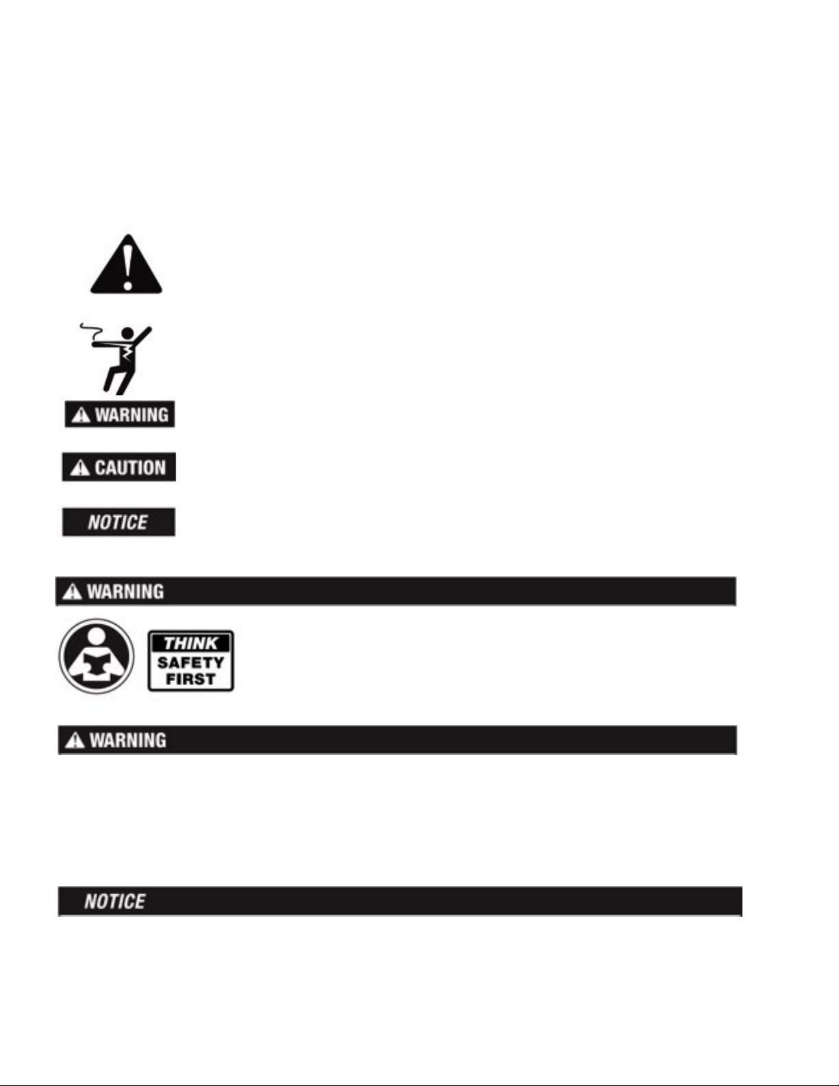
This is a safety-alert symbol. The safety alert symbol is shown alone or used with
a signal word (DANGER, WARNING, or CAUTION), a pictorial and/or a safety
message to identify hazards.
When you see this symbol alone or with a signal word on your equipment or in
this Manual, be alert to the potential for death or serious personal injury.
This pictorial alerts you to electricity, electrocution, and shock hazards.
This symbol identifies hazards which, if not avoided, could result in death or
serious injury.
This symbol identifies hazards which, if not avoided, could result in minor or
moderate injury.
This symbol identifies practices, actions, or failure to act which could result in
property damage or damage to the equipment.
Read Manual and all product labels BEFORE using the equipment.
Do not use unless you know the safe and proper operation of this
equipment. Keep this Manual available for easy access by all users.
• It is the installer's responsibility to ensure that this thermostat is safely installed according to
all applicable codes and standards.
• Improper installation and operation of this thermostat could result in damage to the equipment
and possibly even personal injury or death.
• This thermostat is not intended for use as a primary limit control.
Do not attempt to service the thermostat. There are no user serviceable parts inside the
thermostat. Attempting to do so voids warranty.

Installation
Preparation:
Tools Required ------------------------------------------------------
• Flat Blade or jeweler screwdriver
• Phillips head screwdriver
• Wire stripper
• Drill (for wall anchor)
• 3/16" drill bit (for wall anchor)
Materials Required —————————————————————————
• 18 AWG LVT Solid Wire (Low Voltage Connections)
Installation Installation Location -------------------------------------------------
Consider the following:
• Interior Wall.
• Keep dry. Avoid potential leakage onto the control.
• Relative Humidity less than 90%. Non-condensing environment.
• No exposure to extreme temperatures beyond 32-122°F (0-50°C).
• No draft, direct sun, or other cause for inaccurate temperature readings.
• Away from equipment, appliances, or other sources of electrical interference.
• Easy access for wiring, viewing, and adjusting the display screen.
• Approximately 5 feet (1.5 m) off the finished floor.
• The maximum length of wire is 500 feet (150 m).
• Strip wire to 3/8" (10 mm) for all terminal connections.
• Use standard 8 conductor, 18 AWG wire.
Removing The Thermostat Base
While holding the base section in one hand, pull the lower half of the
display front towards you to pivot it away from the base.

Mounting The Thermostat
To prevent the risk of personal injury and/or death, make sure power is not applied
to the thermostat until it is fully installed and ready for final testing. All work must
be done with power to the circuit being worked on turned off.
Please be aware local codes may require this thermostat to be installed or connected
by an electrical
Relay Power Jumpers
The thermostat includes three relay power jumper connectors
located below the wiring hole.
•Set Jumper J1 to On to connect power R to the Rh1 terminal.
• Set Jumper J2 to On to connect power R to the Rh2 wiring
terminal.
• Set Jumper J3 to On connects power R to the Rc wiring terminal.
• Set the jumper to off to disconnect the power from Rh1, Rh2, or
Rc respectively.

Application 562-1
The WiFi Thermostat 562 operates a one or two-stage furnace for heating and an air conditioner
for cooling.
Mechanical ————————————————————————————
Legend
C1 = Air Conditioner
F1 = Furnace
T1 = WiFi Thermostat 562
Electrical -----------------------------------------------------------
Thermostat jumpers:
J1 = On
J2 = On
J3 = On

Application 562-2
The WiFi Thermostat 562 operates a first stage radiant floor and a second stage furnace for
heating, and an air conditioner for cooling.
Mechanical —————————————————————————————
Legend F1 = Furnace. S1 = Optional Floor Sensor 079
B1 = Boiler PS = System Pump S2 = Optional Indoor Sensor
BP = Boiler Pump T1 = WiFi Thermostat ZVC1 = Zone Valve Control
C1 = Air Conditioner V1 = Zone Valve
Electrical —————————————————————————————
Thermostat jumpers:
J1 = On
2 = Off
J3 = Off
and install field jumper
wire from Rh2 to Rc

Application 562-4
The WiFi Thermostat 562 operates a first stage baseboard/radiator and a second stage fan coil for
heating, and an air conditioner for cooling.
Mechanical ———————————————————————————
Legend F1 = Fan Coil T1 = WiFi Thermostat 562
B1 = Boiler PS = System Pump V1 = Radiant Zone Valve
BP = Boiler Pump S1 = Optional Floor Sensor 079 V2 = Fan Coil Zone Valve
C1 = Air Conditioner S2 = Optional Indoor Sensor 084 ZVC1 = Zone Valve Control 304V, 306V
Electrical —————————————————————————————
Thermostat jumpers:
J1 = On
J2 = Off
J3 = Off
and install field jumper
wire from Rh2 to Rc

Sequence of Operation
Heating Operation:
The Heat On symbol is shown on the display when the thermostat is heating. Heating for freeze
protection is provided whenever the air or floor temperature falls below 40°F (4.5°C), regardless
of operating mode.
Regular Heating -------------------------------------------------
W1 relay is on when the air temperature falls 1.5°F (1°C) below the Heat To setting. When the
temperature reaches the Heat To setting, the relay turns off. The W2 relay turns on based on
settings selected in the Setup menu. W2 turns off when the air temperature is 0.5°F (0.25°C)
below the Heat To setting.
Radiant Floor Heating ————————————————————————
When Radiant Floor Heating is selected in the setup menu, the W1 relay operates using Pulse
Width Modulation. This improves comfort for radiant systems with high mass floors.
• 100% on time at Heat To setting -1.5°F
• 50% on time at Heat To setting
• 0% on time at Heat To setting + 1.5°F
Floor Sensor for Radiant Floor Heating ———————————————
If a floor sensor is connected, floor minimum and maximum settings are available. For a
combination of air and floor temperature control, leave the internal air sensor on in the setup
menu. A floor minimum can be used to prevent a fast drop in temperature caused by receding
solar exposure. This operation is recommended for areas heated by afternoon sun through large
windows. When the sun sets, it can take a long time for the floors to get warm again. This may
cause the room to cool off too much in the early evening. A floor minimum setting can help with
this condition by maintaining a floor minimum temperature. Keep in mind the floor minimum
temperature will override the air temperature, and if set too high, may overheat the room. A floor
maximum is recommended for rooms with hardwood floors. Setting floor minimum and
maximum temperatures is a way of enhancing the comfort of the living space while protecting
floor coverings.
Warm Weather Shut Down (WWSD) -----------------------------------
The heating system can automatically shut off based upon the outdoor temperature and the
WWSD setting. This provides a convenient way to shut off radiant floor heating.
Cooling Operation
The Cool On symbol is shown on the display when the thermostat is cooling.
• Cooling relay Y1 turns on at Cool To setting + 1.5°F (1°C)
• Cooling relay Y1 turns off at Cool To setting
Cold Weather Shut Down (CWSD) -------------------------
The cooling system can automatically shut off based upon the outdoor temperature and CWSD
setting. This prevents unwanted cooling during the winter.
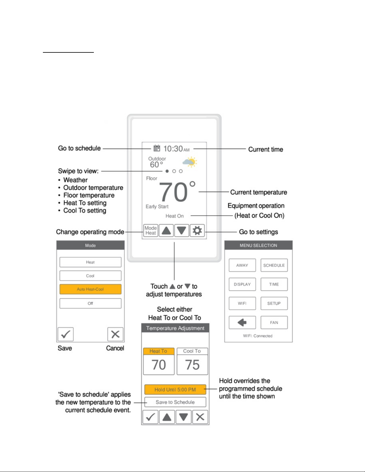
User Interface
Home Screen
After 60 seconds of inactivity, the thermostat home screen displays only the time and the
temperature.
User Settings
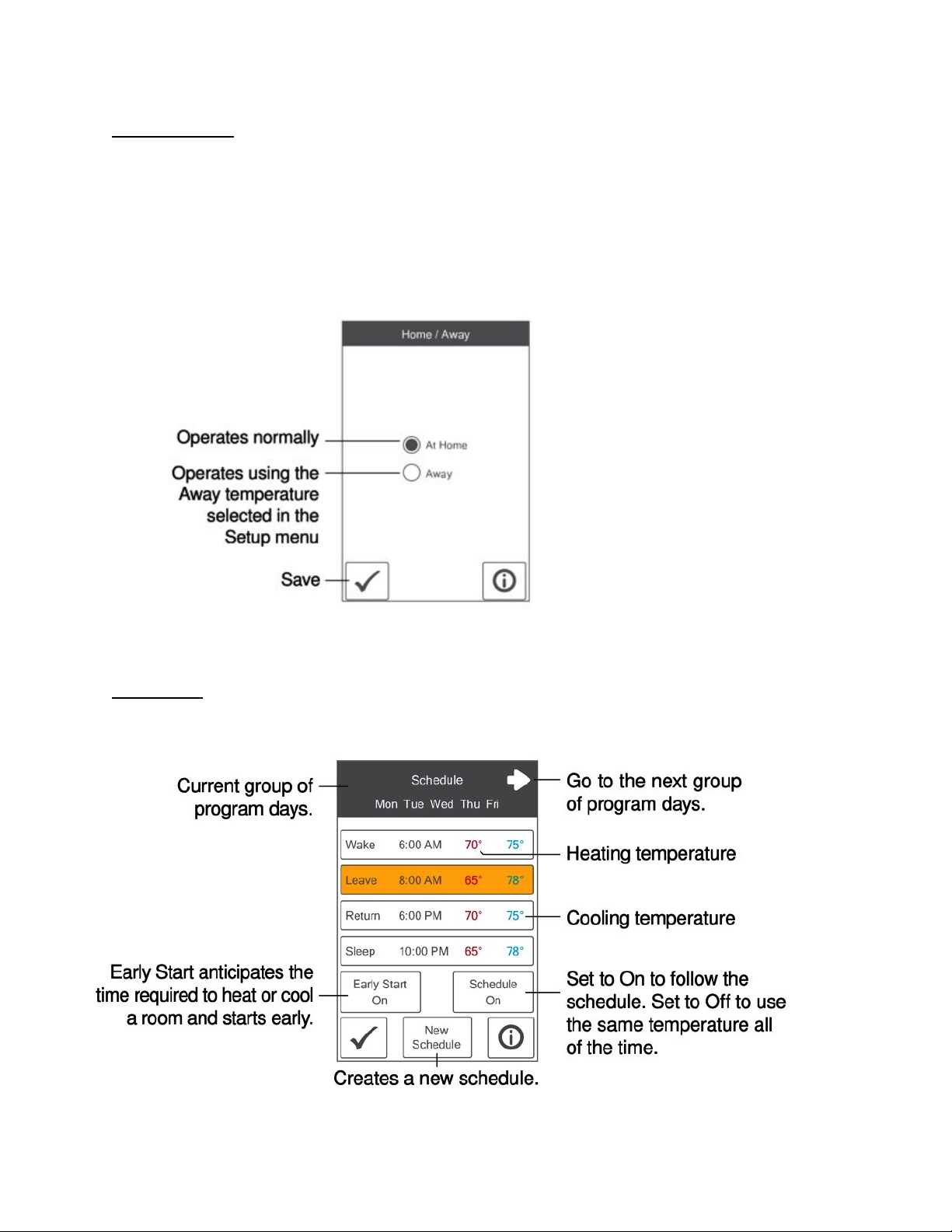
Away
Use the Away setting to save energy when the building is unoccupied.
The away setting is shared to:
• All WiFi Thermostats in a mobile app "Location"
Schedule:

Schedule:
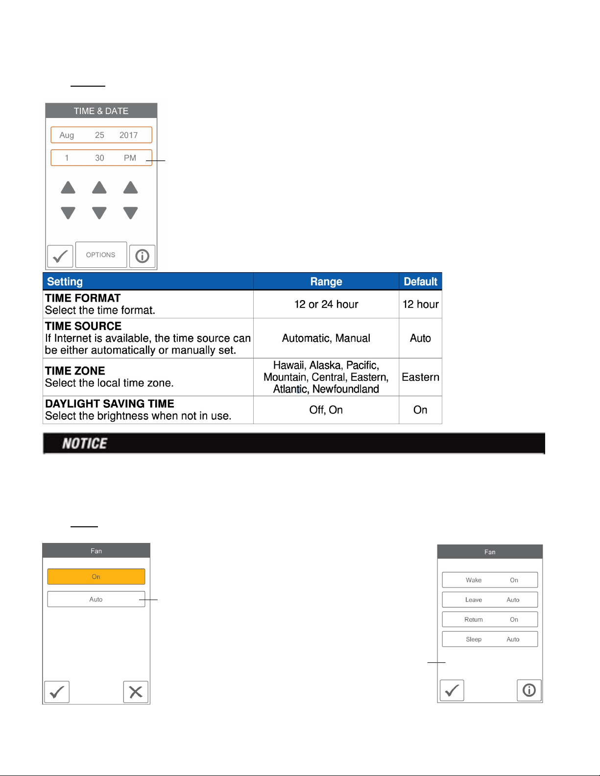
Time:
When connected to the Internet, the time can be set automatically.
The time and date can be manually set by highlighting a field and then
using the or buttons.
Choose from the time options listed below
Incorrectly setting the time and date manually may prevent the thermostat from communicating
to the mobile app. Automatic time source is recommended when using an Internet connection.
Fan:
The fan is normally off when set to auto but turns
on when needed for the heating or cooling
equipment.
When a programmable schedule is use, there is a
fan setting for each time period.
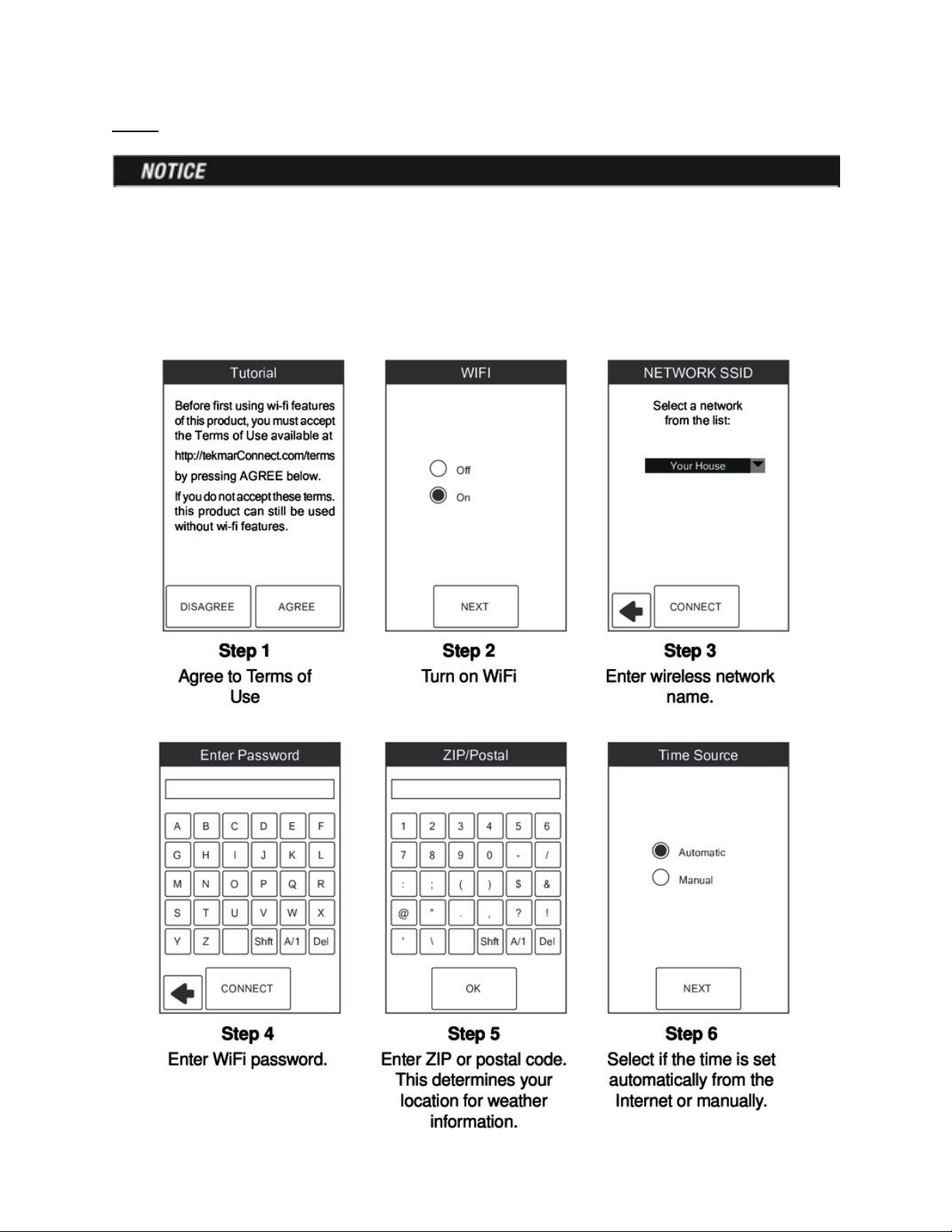
WiFi:
Before using the WiFi features of this product, you must accept the Terms of Use, as amended
from time to time and available at tekmarConnect.com/terms. If you do not accept these terms,
this product can still be used without WiFi features. This product requires WiFi WPA security.
WEP is not supported.
The thermostat includes a step by step tutorial to setup the WiFi connection.

Installer Setting
Setup:
The Setup menu contains five sub-menus that determine
how the thermostat operates.
The Access Level setting in the Toolbox menu determines
how many settings are available to the user
Press back to return to the main
settings menu.
Setup - Toolbox:
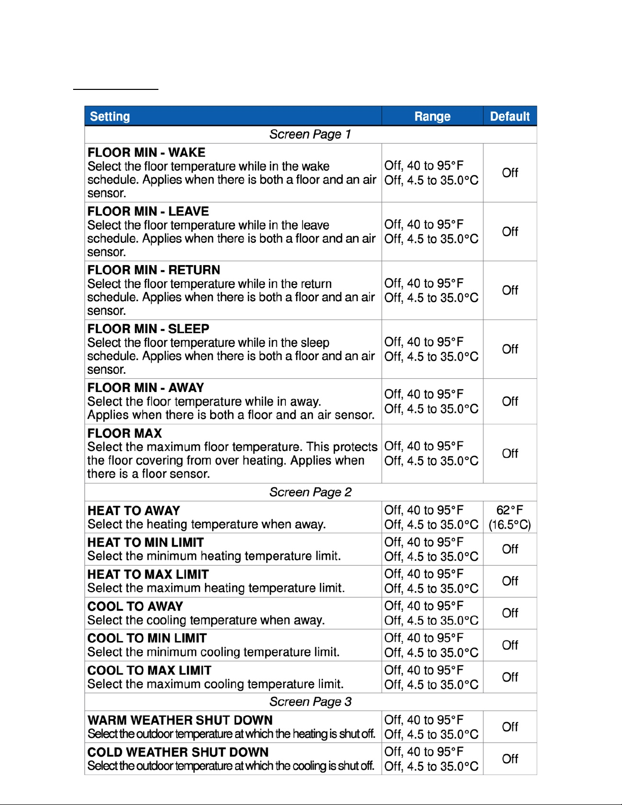
Setup - Temp:
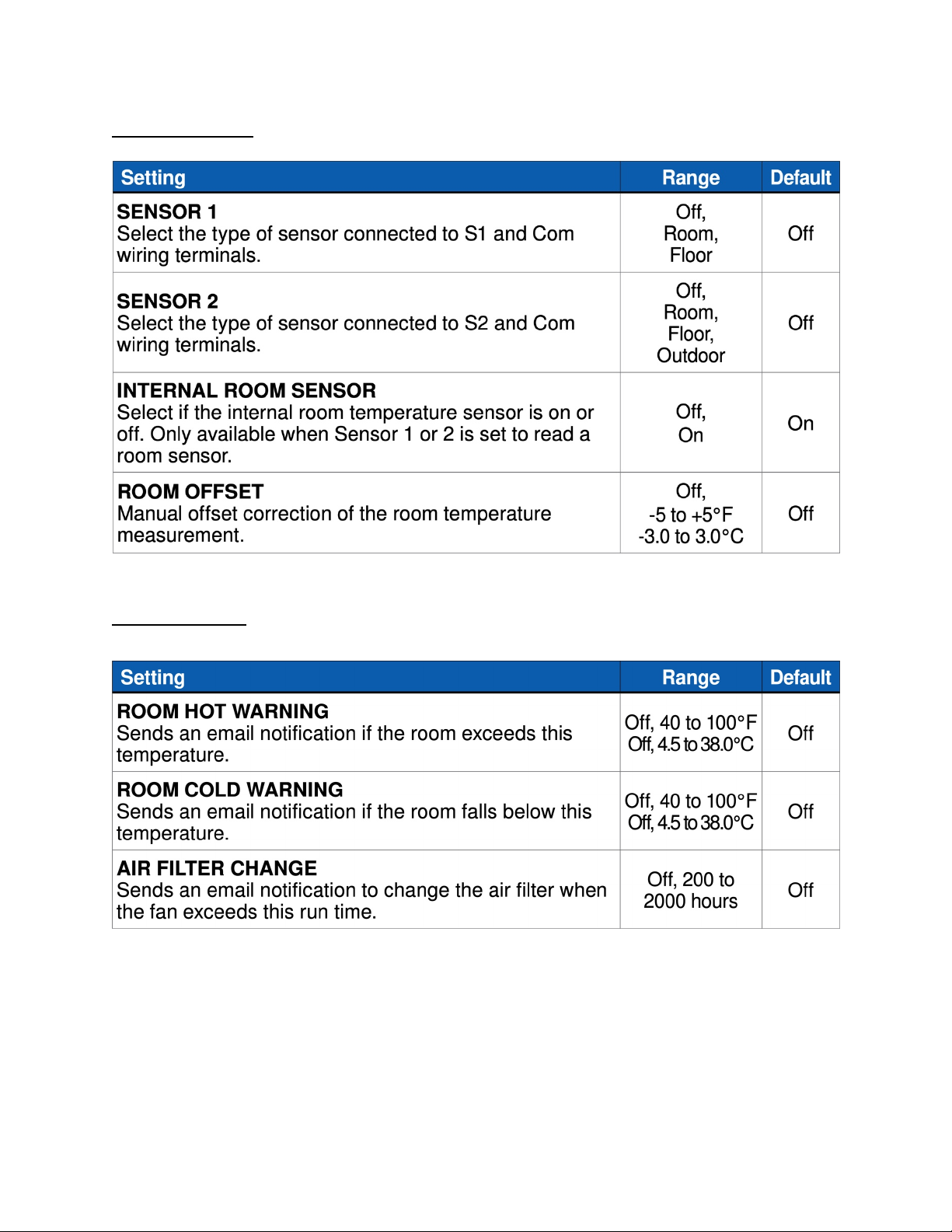
Setup - Sensor:
Setup - Alerts:

Setup - Relays

Tekmar Connect Web and Mobile App
To view and adjust the WiFi Thermostat using a mobile phone or tablet, download the tekmar
Connect mobile app from the Apple® iTunes® Store or from the Google Play® Store.
Alternatively, go to tekmarConnect.com for web browser access.
Add Thermostat to App————————————————————————————
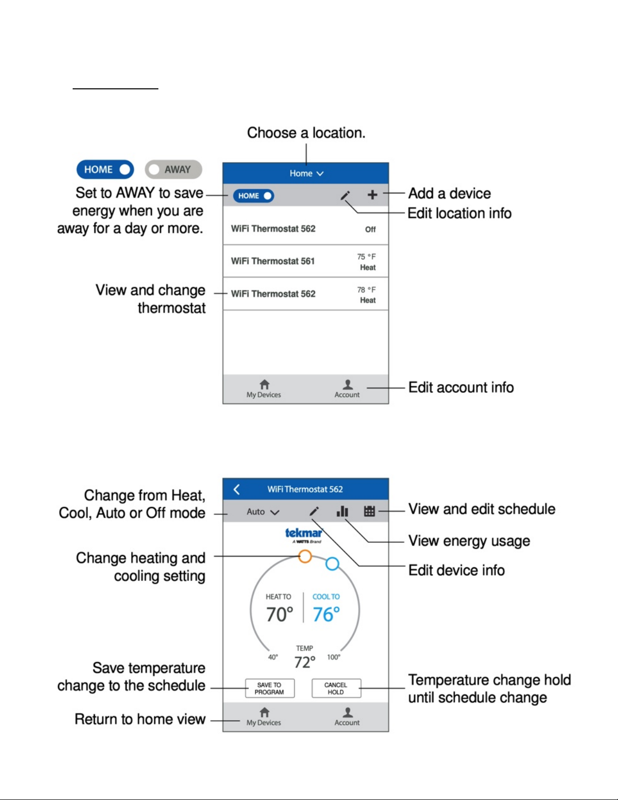
Using the App

Troubleshooting
Error Message
When an error occurs an email notification will be sent to the registered tekmar Connect mobile
or web app account owner
Description:
MEMORY ERROR
The thermostat memory settings are corrupted. To clear, load the factory defaults in the Toolbox
menu. The thermostat will not operate any heating or cooling equipment while this error message
is present.
INTERNAL ROOM SENSOR FAULT
Due to an open or short circuit, the thermostat is unable to read the internal room temperature
sensor. If sensor 1 or 2 is set to room the thermostat continues to operate, otherwise operation
stops. The error cannot be field repaired. Contact your tekmar sales representative for warranty
or repair procedures
SENSOR 1 FAULT
Due to an open or short circuit, the thermostat is unable to read the sensor wired to S1 and Com.
The thermostat stops normal operation if sensor 1 is the only active room or floor sensor or if a
floor maximum temperature has been set. Check the auxiliary sensor wire for short circuits
according to the sensor installation manual. It may be necessary to replace the auxiliary sensor.
Once the error has been corrected, the error message automatically clears.
SENSOR 2 FAULT
Due to an open or short circuit, the thermostat is unable to read the sensor wired to S2 and Com.
The thermostat stops normal operation if sensor 2 is the only active room or floor sensor or if a
floor maximum temperature has been set. Check the auxiliary sensor wire for short circuits
according to the sensor installation manual. It may be necessary to replace the auxiliary sensor.
Once the error has been corrected, the error message automatically clears
ROOM HOT WARNING
The room temperature is above the Room Hot Warning setting in the Alerts menu. The warning
will automatically clear once the room temperature falls below the setting.
ROOM COLD WARNING
The room temperature is below the Room Cold Warning setting in the Alerts menu. The warning
will automatically clear once the room temperature rises above the setting.
CHANGE AIR FILTER
The fan run time has exceeded the Change Air Filter setting in the Alerts menu. To ensure clean
air it is recommended to replace the air filter on the heating and cooling equipment. While
viewing the warning, press the Clear button to clear the warning and reset the fan run time
counter
Table of contents
Popular Thermostat manuals by other brands

Vive Comfort
Vive Comfort TP-N-621 Operation manual

Viessmann
Viessmann VITOTROL 100 operating instructions

Honeywell
Honeywell Digital Round T8775A installation instructions

Honeywell
Honeywell RCT8101 operating manual

Robertshaw
Robertshaw 9560 user manual

Emerson
Emerson 1F83H-21NP Installation and operation instructions

Johnson Controls
Johnson Controls TEC3000 Series quick start guide

DELTA DORE
DELTA DORE TYBOX 137 manual

HomeMatic
HomeMatic HmIP-eTRV-C-2 Mounting instruction and operating manual

Pro1 Technologies
Pro1 Technologies T731W installation manual

HAI
HAI RC-80 Omnistat installation manual

JG
JG Speedfit Aura manual


 Full user manual")

