CryopAL TP-35 User manual

1
Self-pressurizing storage tanks
TP 35 – TP 60 – TP 100
User’s manual

2
Copyright 2017 by Cryopal
Document code: NH78163 – English version
Edition January 2017 – Revision I
All rights reserved. This document may not be reproduced in any form whatsoever, in whole or in part, without
written permission from Cryopal.
Cryopal
Parc Gustave Eiffel
8 Avenue Gutenberg
CS 10172 Bussy Saint Georges
F - 77607 Marne la Vallée Cedex 3
Tel: +33 (0)1.64.76.15.00
Fax: +33 (0)1.64.76.16.99
Web: http://www.cryopal.com

3
Contents
1.
About this manual ............................................5
1.1
Purpose of the manual ...............................5
1.2
Who this manual is for................................5
1.3
Structure of the manual..............................5
1.4
How to use this manual..............................5
1.5
Skimming the manual.................................5
1.6
The included document..............................5
1.7
Trade names cited......................................5
2.
Safety.................................................................6
2.1
Symbols used.............................................6
2.2
Operator safety...........................................6
2.3
Precautions in the event of operating faults7
2.4
Important Safety Elements (ISE)................7
2.5
Destruction of the unit.................................8
3.
Components supplied....................................10
4.
General.............................................................12
4.1
Guide to components ...............................12
4.2
Function....................................................12
4.3
Principle....................................................12
5.
Description......................................................14
5.1
Storage tank .............................................14
5.2
The control head.......................................15
5.3
Main accessories......................................15
6.
Unpacking and installation............................18
6.1
Unpacking.................................................18
6.2
Installation.................................................18
6.3
Installation checklist..................................18
7.
Installing the components .............................20
7.1
Control head.............................................20
7.2
Removing the control head.......................21
8.
Use ...................................................................22
8.1
Storage precautions .................................22
8.2
Moving......................................................22
8.3
Handling....................................................22
8.4
Filling the tank ..........................................22
8.5
Withdrawal................................................24
9.
Maintenance....................................................26
9.1
Operating incidents...................................26
9.2
Preventive maintenance...........................27
9.3
Inspections ...............................................27
9.4
Adjusting the level indicator......................29
9.5
Changing components..............................30
9.6
Interview frequency ..................................31
10.
Technical specifications.................................34
10.1
Tank..........................................................34
10.2
Control head..............................................35
11.
Spare parts and accessories .........................36
11.1
Tank..........................................................36
11.2
Control head..............................................36
11.3
Accessories...............................................37
12.
Warranty and limit of liability.........................38
12.1
Warranty....................................................38
12.2
Limit of liability...........................................38
13.
Index.................................................................40

4

5
1. About this manual
1.1 Purpose of the manual
This manual refers specifically to cryogenic storage
tanks in the TP range, i.e. self-pressurizing tanks
intended for storing and transporting liquid nitrogen.
1.2 Who this manual is for
This manual is for any professional who wishes to use
a cryogenic container in the TP line.
1.3 Structure of the manual
For ease of consultation, the structure of this manual
follows the steps normally taken by the user, as
described below:
Topic Page
Overview of the TP tank 12
Assembly (parts and options) 20
Use 22
Maintenance 26
Technical specifications 3434
1.4 How to use this manual
The instructions in this manual are in the same
sequence as those followed by the users of the
product (section 1.3).
1.5 Skimming the manual
Given the specific nature of the cryogenic products
and storage tanks, we would advise against skimming
through this manual. We strongly recommend reading
the chapters thoroughly in the order given.
1.6 The included document
The accompanying document contains:
This manual in electronic pdf format.
Manuals issued by Cryopal.
Note: you will need to have the software known as
Acrobat Reader installed on your computer to be
able to read or print from this pdf manual in pdf
format.
1.7 Trade names cited
Adobe and Adobe Acrobat Reader are trademarks of
Adobe Systems Incorporated.

6
2. Safety
2.1 Symbols used
Symbol Meaning
Important
information about using the
equipment. Failure to follow the
instructions given for this point does not
result in danger for the user.
Warning: General danger. In this
manual, failure to observe or
implement the instructions preceded
by this symbol may
cause bodily
harm, or may damage the equipment
and installations.
Name and address of manufacturer.
Mandatory
: Protect your hands using
appropriate personal protection
equipment.
Warning
: Low temperature.
Product reference
Date of
manufacturing
Capacity in liters
Batch number
To maintain perfect operating conditions and ensure
that the equipment is used safely, you must follow the
instructions and take note of the symbols given in this
manual. The tank has been designed for
liquid nitrogen only.
When the device cannot be used in conditions of total
safety, the equipment should be withdrawn from
information about using the
equipment. Failure to follow the
instructions given for this point does not
result in danger for the user.
Warning: General danger. In this
manual, failure to observe or
implement the instructions preceded
cause bodily
harm, or may damage the equipment
Name and address of manufacturer.
: Protect your hands using
appropriate personal protection
: Low temperature.
To maintain perfect operating conditions and ensure
that the equipment is used safely, you must follow the
instructions and take note of the symbols given in this
manual. The tank has been designed for
use with
When the device cannot be used in conditions of total
safety, the equipment should be withdrawn from
service and protected against accidental usage. Full
safety cannot be guaranteed in the following cases:
The equipment is
visibly damaged.
The equipment no longer works (applies
particularly to accessories).
After prolonged storage in unsuitable conditions.
After severe damage sustained during transit.
2.2
Operator safety
2.2.1
General safety precautions
Only personnel who have fully read this manual
and the safety recommendations (see NH78380)
are authorized to handle and use the apparatus
described in this document.
Like every other system, your apparatus may be
subject to a mechanical
failure. The manufacturer
cannot be held liable for any production losses
subsequent to defective operation of the kind
described above, even during the warranty period.
If the cryogenic tank appears to have an operating
fault when used under normal condi
properly trained and qualified personnel are
permitted to service it. The user must not be
permitted to attempt repairs as this could present
a risk to that person's health and/or safety.
The equipment described in this manual is designed
exclu
sively for use by qualified personnel.
Maintenance operations should only be carried out by
qualified and authorized personnel. To ensure the
safe and correct use of the device during service and
maintenance, it is essential that all personnel observe
standard safety procedures.
service and protected against accidental usage. Full
safety cannot be guaranteed in the following cases:
visibly damaged.
The equipment no longer works (applies
particularly to accessories).
After prolonged storage in unsuitable conditions.
After severe damage sustained during transit.
Operator safety
General safety precautions
Only personnel who have fully read this manual
and the safety recommendations (see NH78380)
are authorized to handle and use the apparatus
described in this document.
Like every other system, your apparatus may be
failure. The manufacturer
cannot be held liable for any production losses
subsequent to defective operation of the kind
described above, even during the warranty period.
If the cryogenic tank appears to have an operating
fault when used under normal condi
tions, only
properly trained and qualified personnel are
permitted to service it. The user must not be
permitted to attempt repairs as this could present
a risk to that person's health and/or safety.
The equipment described in this manual is designed
sively for use by qualified personnel.
Maintenance operations should only be carried out by
qualified and authorized personnel. To ensure the
safe and correct use of the device during service and
maintenance, it is essential that all personnel observe

7
2.2.2 Safe use of liquid nitrogen
The temperature of liquid nitrogen is -196 °C. As a
result:
You must never touch objects which
have been in contact with liquid
nitrogen with your bare hands.
Always wear special gloves and visors
when handling liquid nitrogen
Liquid nitrogen used in storage
freezing chambers evaporates into the
air; 1 litre of liquid nitrogen releases
around 700 litres of nitrogen in the
gaseous state. Nitrogen is an inert,
non-toxic gas, but displaces oxygen
when released into the atmosphere.
Once the atmospheric oxygen content
falls below 19% there is a risk for
humans.
Any room or place where liquid
nitrogen containers are kept must
always be completely ventilated and, at
least, equipped with an oxygen
detector; it should not be used for
other purposes than those defined by
your integrator. All personnel should
be informed of the risks associated
with the use of nitrogen.
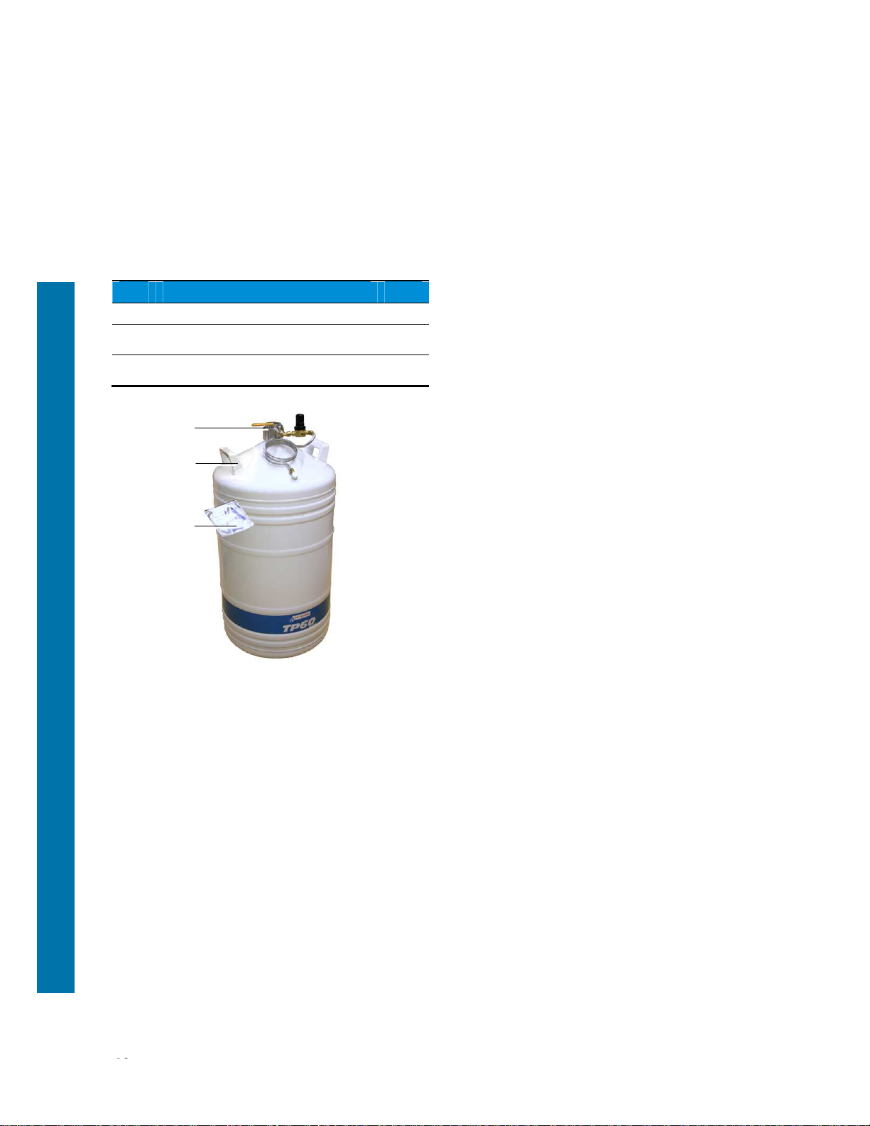
The storage tank is designed for use
with liquid nitrogen only.
When in new condition, the tank must
always be transported empty, in its
original packaging and in compliance
with current national and international
regulations. Never stack storage tanks
on top of each other.
According to the ADR directive on
transporting dangerous goods by road,
in order to avoid falling under the
TPED directive, TP tanks must be
transported without being under
pressure (at atmospheric pressure)
and with their neck open.
The tank may be moved across short
distances (using the dolly base) with
its head installed, with the tank not
being under pressure (i.e. at
atmospheric pressure).
If the tank is moved without the head,
the control head can be reinstalled in
the tank once full. This installation
phase must be conducted with caution
(
operator equipped with all required
cryogenic personal protection
equipment: gloves, apron, visor, etc.)
in order to avoid any liquid nitrogen
splashing.
The neck of the tank must never be
hermetically sealed. Use the stopper
provided.
The tank must always be kept vertical.
2.3 Precautions in the event of
operating faults
If you suspect that the integrity of the equipment has
been compromised (for example as a result of
damage sustained during transit or during use), it
should be withdrawn from service. Make sure that the
withdrawn equipment cannot be accidentally used by
others. The defective equipment should be handed
over to authorized technicians for inspection.
2.4 Important Safety Elements
(ISE)
These ISE are:
Design rules for the EC Medical directives.
Technical documentation (maintenance
instructions and services),
Components integral to the products (valves,
solenoid valves, electronic equipment such as
control and traceability electronics, overflow
prevention and degassing devices, sensors and
interfaces for remote monitoring (by an automation
controller etc.), the cover contact); these elements
are not necessarily present on the product.
Obligatory safety recommendations or advice (the
wearing of personal protection equipment when
using our products, instructions for the use of
equipment etc.).
During filling and transfer operations, ensure that
equipment and procedures that ensure safety are
used (hose, vacuum valve).

8
2.5 Destruction of the unit
In order to protect the environment the equipment (the
tank and its peripheral equipment) must be disposed
of via the proper channels.

9

10
3. Components supplied
The product is delivered complete with:
Ref. Designation Qty
1.
Insulating stopper. 1
2.
ATP container (see table of capacities on
page 34). 1
3.
Document containing this manual in pdf
format. 1
Figure 3-1: The delivered parts.
1
2
3

11

12
4. General
4.1 Guide to components
This illustration shows the main parts, both included
ones and options that make up a storage tank in the
TP
product line. These are described in greater detail
in the following paragraphs and pages. The tanks will
be used in an appropriate environment.
Figure 4-1: General view of the parts of a type TP storage tank.
4.2 Function
Cryogenic containers in the
TP
range are self-
pressurizing aluminium storage tanks for storing and
withdrawing liquid nitrogen at low pressures. A float-
type level indicator enables the amount of available
liquid to be checked. The removable control head is
fitted with a pressure gauge and two safety valves.
4.3 Principle
The storage tank contains liquid nitrogen. It is
pressurised by means of an exchanger (9) [regulating
valve (7) and shutoff valve (8)] located between the
walls. This exchanger vaporises liquid gas and thus
ensures that the tank is pressurised. The pressure
can be read off the pressure gauge (1). Two safety
valves (2) calibrated to 0.5 bars protect the tank. It is
filled via the connector (3) and valve (4) assembly.
Figure 4-2: Principle.
Ref. Designation
1. Internal pressure gauge.
2. Safety valves.
3. Connector (filling/withdrawing)
4. Filling and withdrawing valve.
5. Mechanical level indicator.
6. Venting /overflow valve.
7. Internal pressure regulating valve.
8. Pressure-building valve.
9. Pressure-building coil.

13

14
5. Description
This section describes the two main parts, i.e. the
storage tank and the control head.
5.1 Storage tank
The self-pressurizing aluminium storage tank enables
liquid nitrogen to be stored and withdrawn. It consists
of the following parts:
A tank (6) consisting of two aluminium alloy
enclosures connected by a collar of composite
materials. It is thermally insulated by means of a
vacuum between the two annular spaces and
several layers of insulation on the internal
container. The exterior of the tank is coated with
polyurethane paint for a good finish and durability.
A flange head DN50 (3), onto which the control
head is fastened (see next section).
Two handles (5).
A vacuum valve (7) which also acts to keep the
annular spaces safe.
A controller (2) intended to control the tank's once
the installed control head and the pressure-
building valve (1) have been opened. The basic
setting is 0.5 bar.
A pressure-building heating coil (4).
An insulating, enclosing stopper (8) that limits
nitrogen loss. This stopper must be placed on the
flange whenever the control head is not fitted on
the tank.
The neck of the tank must never be
hermetically sealed.
Two self-adhesive labels carrying warnings and
product identification.
Refer to:
On page 12 for details of how these components
operate.
On page 34 for the technical specifications of the
various models.
Figure 5-1: Overview of the tank
Ref. Function
1. Pressure-building valve.
2. Controller.
3. Head flange, nom. dia. 50 mm
4. Heating coil.
5. Handle
6. Tank.
7. Annular space safety device.
8. Stopper.
1
2
3
4
5
6
7
8

15
5.2 The control head
The control head can provide a quick check of the
amount of available liquid in the tank. It includes the
following withdrawal, level reading and safety devices:
Figure 5-2: Overview of the control head.
Ref. Function
1. Mechanical level indicator.
2. Filling / withdrawing valve.
3. Filling/utilisation connector.
4. 0.5 bar valves.
5. Pressure gauge (internal pressure).
6. Venting /overflow valve.
7. Venting connector
8. Quick-release clamping ring
9. Leak proof seal.
A floating level indicator (1). The coloured part
shows the percentage of liquid nitrogen remaining.
A filling valve (2) and its connector (3) for
connecting to the supply tank connector or to the
supply line via a suitable flexible transfer line. This
valve (2) and its connector (3) are also used for
withdrawal (drawing liquid nitrogen off into another
vessel for use).
Two safety valves calibrated to 0.5 bar (4),
protecting the tank from any excess internal
pressure .
A pointing pressure gauge (5) indicating the tank's
internal pressure in bars (kPa). A red mark at 0.5
bars shows the maximum service pressure of the
TP
.
A venting and overflow valve (6) and its connector
(7).
A quick-release clamping rings (8) to fit the control
head on the storage tank flange.
A seal (9) that prevents any leakage between the
control head and the storage tank flange.
Refer to:
On page 12 for details of how these components
operate.
En On page 35 for the technical specifications.
5.3 Main accessories
These accessories are not supplied with the standard
version and must be ordered separately.
5.3.1 Dolly base
This base (1) can be firmly clamped to the tank and
enables it to be moved inside a building, making it
easier to negotiate uneven floors. It has five castors,
two of which have brakes.
Figure 5-3: Container mounted on the dolly base.
5.3.2 Hand rail
This removable metal accessory (1) makes it easy to
move the tank and also protects the control head. The
handrail (1) fastens on to two lugs mounted on the
tank handles.
Figure 5-4: View of the handrail mounted on a tank.
1
2
3
4
5
6
7
8
9
1
1

16
5.3.3 Flexible transfer lines
5.3.3.1 Type 130/130
This flexible transfer line (or hose), which vary in
length, is intended to fill the
TP
from a supply tank or
vacuum line. There is a screw-on connector at both
ends. One end is connected to the source valve outlet
and the other to the connector (Figure 5-2) on the TP
storage tank.
Figure 5-5: View of the 130/130 transfer line.
Ref. Function
1. Screw-on connector.
2. Flexible line.
Cryopal flexible lines comply with the
EN12434 standard.
It is essential to ensure that a safety
valve calibrated to 15 bar maximum is
inserted at one end of the flexible line
(on condition that the operating
pressure of the line is greater than or
equal to 15 bar gauge pressure).
As a reminder, using any accessories
(hoses, fittings etc.) that do not comply
with the requirements set forth by
voids
the manufacturer's liability and warranty
.
We therefore ask you to check that any
flexible lines or connectors used (other
than those supplied by Cryopal) are
approved and certified for an operating
pressure of 15 bar (gauge bar).
5.3.3.2
Type 130 TC
This hose (1), which is 0.80 m in length, is intended
for transferring between a
TP
tank and a
TR
tank or a
different one. There is a screw-on connector (4) at
one end for connection to the withdrawal valve outlet.
A 10 mm diameter rigid tube (3) with a protective
handle (2) is attached to the other end.
Figure 5-6: View of the 130 TC transfer line.
Ref. Function
1. Flexible pipe.
2. Handle.
3. 10 mm diameter rigid tube.
4. Screw-on connector.
1
2
1
4
3
2
1

17

18
6. Unpacking and installation
6.1 Unpacking
For your own safety you must observe the safety rules
and use suitable tools for unpacking and personal
protection equipment.
At least two able people are needed to unpack the
assembly.
Check the condition of the packaging on delivery.
Unpack the equipment as close as possible to its
place of use to avoid having to move it any great
distance.
Cut the straps and remove the lid.
Remove the tank.
6.2 Installation
The customer is responsible for ensuring that the
premises comply with current regulations and safety
standards and with the following recommendations.
The maximum pressure of liquid nitrogen
supply must be below 3 bars (1.5 bars
recommended). Using a higher pressure
may damage the equipment.
The volume of liquid nitrogen available is
determined by the quantity of liquid present
between the minimum level and the
maximum filling level in the supplying tank.
Before connecting the flexible filling line to
the supplying tank or the liquid nitrogen
supply it is important to purge the lines with
dry nitrogen in order to remove any trace of
moisture.
6.3 Installation checklist
Action Yes,
done No, not
done
Check the general
condition of the apparatus.
Are the users trained?
Does the room satisfy
safety regulations and
standards in force?
Are the dimensions of the
room (in particular the clear
ceiling height after opening
the lid) suitable for
installation of the medical
apparatus?
Is access to the room
limited to persons entitled
to enter it?
Are safety instructions and
risks related to liquid
nitrogen posted?
Are instructions available /
accessible close to it?
Is personal protection
equipment available /
accessible in the room?
Is the room equipped with a
permanent ventilation
system suitable for the size
of the room?
Is the room equipped with
an oxygen content
checking system (display
outside the room)?
Are safe distances
observed (at least 0.5 m

19
Action Yes,
done No, not
done
around the apparatus)?
Is the liquid nitrogen supply
pressure lower than 3
bars?
Has the medical apparatus
been blown through (to
eliminate all traces of
moisture)?

20
7. Installing the components
This section describes how to add various peripheral
devices (control head, castor base) to the storage
tank.
7.1 Control head
Proceed as follows:
The control head can be installed in the full
tank. This installation phase must be
conducted with caution (trained operator,
equipped with all required cryogenic
personal protection equipment: gloves,
apron, visor, etc.) in order to avoid any
liquid nitrogen splashing.
1. Before starting, blow dry air or nitrogen through the
lines and the valves to remove any moisture.
This is an essential precaution to avoid the
risks of ice forming in the lines and the
safety accessories and blocking them or
preventing them from working.
2. Open the vent valve (2).
Close the filling/withdrawal valve (1).
Close the pressure-building valve (3).
You must ensure that these two valves
are closed before doing anything else.
3. Fit the metal seal (5) over the flange of the tank.
The length of the control head means that you
must be aware of equipment above you when
installing it (see below).
4. Introduce the bottom of the control head (4) into
the tank, taking care not to knock the neck of the
inner vessel.
5. Position the clamping ring (6) and secure the
assembly.
4
5
6
This manual suits for next models
2
Table of contents