Crystal Clear CC3272 User manual

AUTOMATIC POOL CLEANER OPERATING MANUAL.
CC3272
Model
Cleans pool
floor
Minimum Horse
Power Pump
Combo. min.
Filter/Pump
Pool - Type
Min. Operating
Flow Rate
CC3272
Yes
0.25Hp
CC2013
Above/In -
Ground
>4m³/H
Fast Start-up, Safely Operate and
Efficiently Clean!
PAGE 2
SUCTION HAZARD - When using the pool cleaner, keep it away from body parts
when the cleaner is connected to suction.
CHILD DROWNING RISK - Adult use only. Never allow children to use the
pool cleaner. Do not allow swimmers in the pool during cleaner operation. Store
out of the reach of children.
Before you assemble and install your pool cleaner, we strongly recommend you carry out the
following steps to ensure your pool is ready for your cleaner to operate.
1. Make sure the chemical balance of your pool water is correct.
2. Brush your pool and let any debris settle.
3. Vacuum your pool, using a manual vacuum cleaner.
4. Clean your pool filter, skimmer basket and pump strainer basket.
5. Close the pool main drain. (If your pool has one.)
6. Adjust the pool return lines so the water flow is directed downward to ensure complete
cleaning of your pool. The flow of water from the return line(s) can affect the
performance of pool cleaner, as it can push the cleaner away from certain areas, or
cause it to stay in one section of the pool. To turn the flow downward simply:
•Loosen the lock ring.
•Turn the eyeball, so the flow is directed downward.
•Retighten the lock ring.
7. If necessary, replace the eyeball fitting with the Return Line Diverter supplied with your
pool cleaner. To do so, simply:
•Make sure the pool pump is switched off.
•Unscrew the lock ring.
•Replace the original eyeball with the Return Line Diverter.
•Make sure the Return Line Diverter is positioned so as to direct the flow downwards.
! WARNING
SAFETY INSTRUCTIONS: - Read Prior to Use
PREPARING YOUR POOL

PAGE 3
ASSEMBLING & INSTALLING YOUR POOL CLEANER
STEP1: CHECK CONTENTS
Remove the cleaner body and all parts from the
box and check the following components are
included. Refer to Figure 1.
NO:
Description
Quantity of
components
1
CleanercompletewithFootpad
1
2
Disc
1
3
Hose lengths*
10
4
Deflector Wheel
1
5
Hose Weight
3
6
Flow Control Valve
1
7
Control Valve Adaptor
1
8
Return Line Diverter
1
9
Agile Adaptor
1
STEP2:ASSEMBLETHEPOOLCLEANER
To assemble simply fit your pool cleaner disc
to the body.
Simply stretch the disc (with the fins pointing
up, towards the cleaner) over the Footpad, as
shown in Fig 2. Make sure the inside rim of the
Disc is located in the track that runs around the
Footpad. When the Disc is correctly
positioned, it should easily rotate around the
Footpad.
Figure2
FOOTPAD
DISC

STEP3 USE OF THE DEFLECTOR WHEEL
Use the Deflector Wheel if your pool has
tight corners and/or a ladder. The Deflector
Wheel helps guide your pool cleaner around
these obstacles.
To fit the Deflector Wheel, simply push it
over the Hand nut until it has engaged
correctly and rotates freely See Fig 3.
STEP 4: CONNECT HOSE & POSITION THE HOSE WEIGHT
Connect sufficient lengths of hose
to cover the distance from the pool
skimmer or vacuum point, to the
farthest point of your pool, plus
one length. See Fig 4. The Female
(large) hose cuff is fitted to the pool
cleaner. Opt agile adapter
according to the individual pool
The Male (small) hose cuff
connects to the pool system. See Fig
5.
If you have a deep pool, you may
need to fit the hose weight. This
is to counteract excessive
buoyancy created by the hose.
The hose weight simply slides
over the Male hose cuff and can
then be positioned wherever
required on the hose. Adjusting
the position of the hose weight
could provide better
performance. See Figs 6.
PAGE 4
Figure 5

Figure9
PAGE 5
STEP 5: CONNECTING & USING THE FLOW CONTROL VALVE
The Flow Control Valve ensures your pool cleaner receives the flow required to ensure
optimum performance.
•Make sure the pool pump is turned OFF.
•Expel all the air from the hose.
•Attach Flow Control Valve to the male hose
(smaller end). See Fig 7.
•Insert the Flow Control Valve into the
Weir/Skimmer. If necessary, use the Control
Valve Adaptor to ensure a good connection.
See Fig 8.
•Turn the pool pump ON.
•Your pool cleaner will now begin randomly and
automatically vacuuming your pool.
Figure 7
Attach Male Hose
Adaptor (smaller
end)
Flow Control
Valve
Control Valve
Adaptor
The Flow Control Valve is preset between
positions 3-4. This provides the ideal
operating flow in most pools But if
necessary the flow can be adjusted by
using any setting from Position 1 through
6(1= minimum flow, to slow your cleaner
down 6 = maximum flow, your cleaner will
run faster).See Fig 9.
Top of Skimmer
Figure 8
Hosethrough
Skimmer
Opening
Control Valve
Adaptor
Flow ControlValve
Attach
Hose This
End
Press into bottom
of skimmer
TROUBLESHOOTING
Due to the individual characteristics of your pool, some adjustment may be required
to get the best possible performance from your pool cleaner. The following tips will
help you to optimize the performance of your cleaner.
Problem
Solution
Pool cleaner does not move, or moves slowly.
•Make sure the main drain is closed.
•Check the Flow Control Valve and make sure the flow to
pool cleaner is sufficient.
•Check diaphragm for wear or damage.
•Backwash filter and empty pump strainer basket.
Pool cleaner gets stuck at steps or in a corner.
•Fit Deflector Wheel.
•Make sure total hose length is correct.
•Adjust return line eyeball fittings to use the water flow to
help guide away from the steps or corner.
Pool cleaner moves in a repetitive, non-random
pattern.
•Make sure return line fittings are directed downwards.
•Check that hose weight position is correct.
•Make sure total hose length is correct.
Pool cleaner stays in only one end of the pool.
•Check the return line flow and redirect if necessary.
•Check the total hose length and add more hose if
necessary.
•Check that hose weight position is correct.
Air bubbles can be seen in the flow from the
return line.
•Check the hose to ensure there are no leaks.
•Check the connection of the flow Control Valve, to make
sure it is underwater at all times.
•Check the pump basket lid is fitted correctly, is not loose
or cracked and that no o-rings are worn or missing. If
necessary, contact your pool professional for assistance.
Pool cleaner falls on its side.
•Make sure the Outer Extension Pipe swivels freely.
Hose won't fit Flow Control Valve
•Fit Hose Adaptor to Flow Control valve
ROUTINE MAINTENANCE
To maintain the performance of your pool cleaner:
•When removed from the pool, make sure the hose is stored straight. Never coil the hose
as this may cause distortion which may adversely effect the pool cleaner.
•Remove the Pool cleaner (including hose) before chemical treatment. Wait a minimum of
4 hours after super chlorination (shock treatment) of your pool before re-installing the
pool cleaner.
•Clean the filter, skimmer basket and pump basket regularly.
•When not in use, keep the cleaner disc flat, to avoid risk of warping.
•Periodically inspect your pool cleaner for signs of wear. If necessary, replace any worn
parts.
NOTE: Due to the harsh conditions in which your cleaner operates, its colours may fade
and discolor overtime. PAGE 6
PAGE 7
REPLACING THE DIAPHRAGM
The diaphragm of your pool cleaner operates at the rate of approximately 360 beats per minute. If
your pool cleaner operates daily for 8 hours, the diaphragm will open and close over60 million
times in a year! The design has been perfected over many years and, properly cared for; the
diaphragm will last for several seasons. In the event that it does become worn or damaged and
needs to be replaced, simply follow these easy steps:
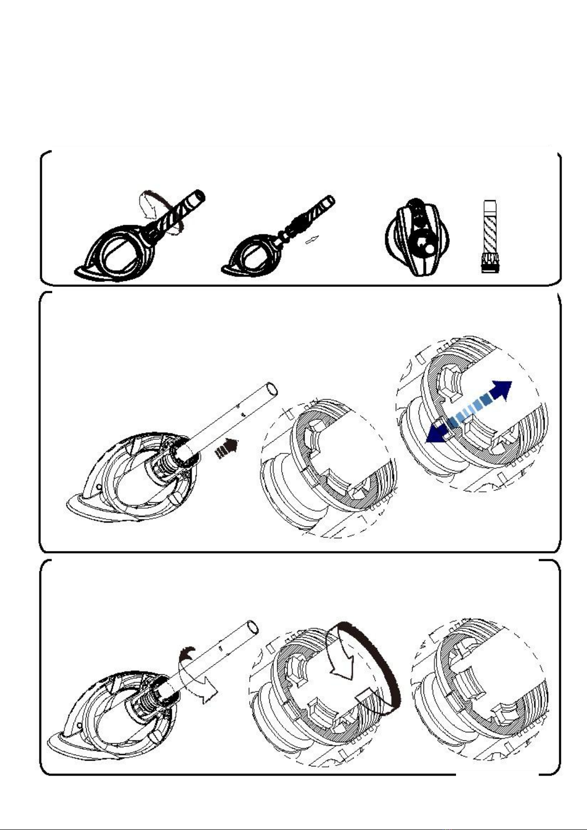
1. Unscrew the HAND NUT and remove it, together with the OUTER EXTENSION PIPE and
the THRUST WASHER. Place these items to one side.
2. Hold the INNER EXTENSION PIPE (IEP) and gently pull it towards you. This pulls the tabs out
of their recess.
3. Turn the INNER EXTENSION PIPE so the tabs line up with the holes in the IEP
LOCATOR. Do not remove the INNER EXTENSION PIPE from the BODY
PAGE 8
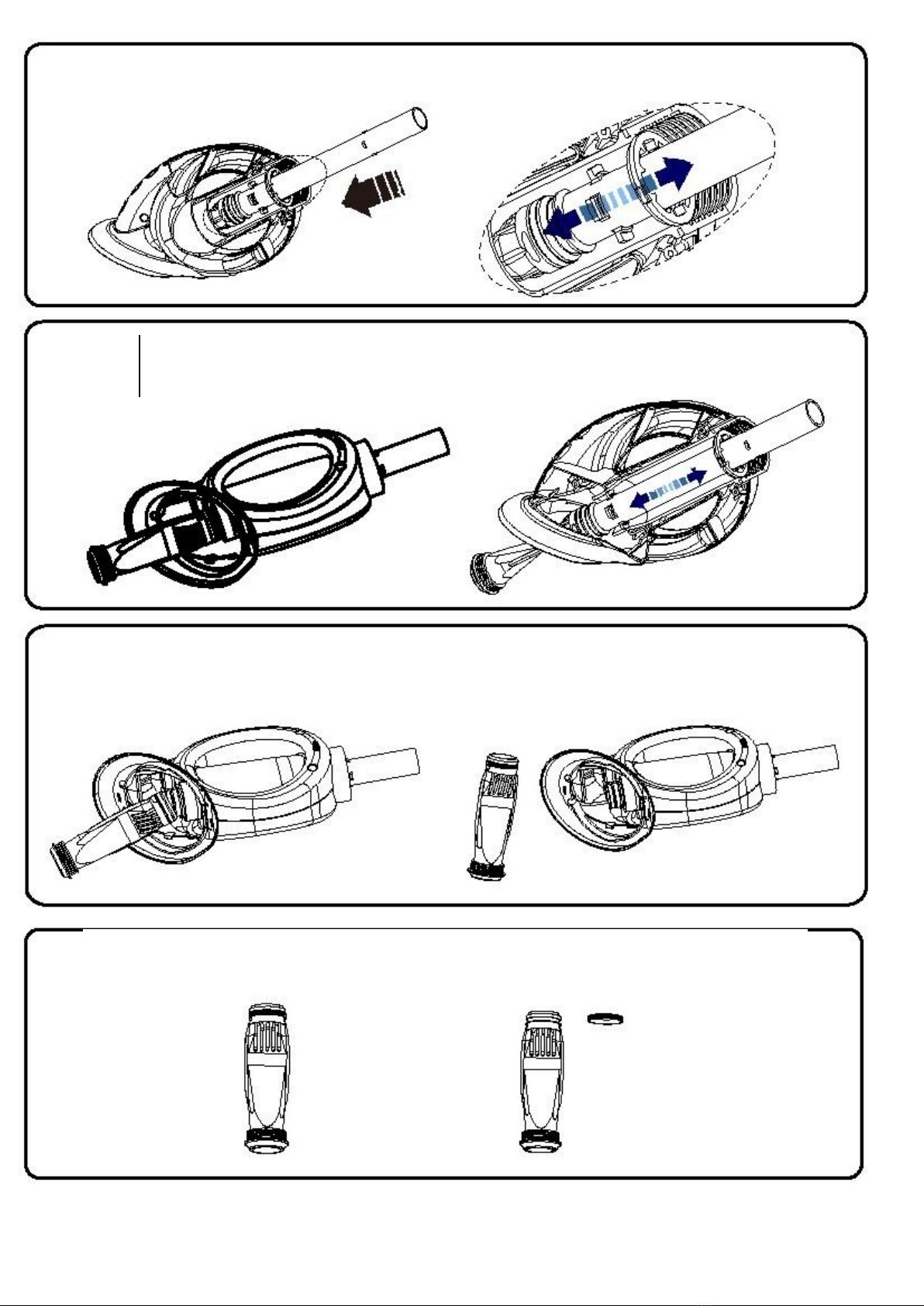
4. Push the INNER EXTENSION PIPE away from you, so the tabs go through the holes
in the IEP LOCATOR.
5. Grasp the other end of the DIAPHRAGM (the end furthest away from the INNER
EXTENSION PIPE) and pull it away from the pool cleaner BODY. The DIAPHRAGM
will fall clear of the BODY.
6. Twist the DIAPHRAGM, removing it from the INNER EXTENSION PIPE.
7. Remove the RETAINING RING from the DIAPHRAGM. Discard the used
diaphragm.

To install a new diaphragm, simply reverse the process:
(b) Push the DIAPHRAGM onto the INNER
EXTENSION PIPE. Make sure it is correctly
located and fully engaged
Gentle turn the INNER EXTENSION PIPE so
the tabs are aligned with the recesses in the
IEP LOCATOR. Release the INNER
EXTENSION PIPE.
Pull the INNER EXTENSION PIPE up
through the BODY, positioning the tabs so
they can be pulled through the holes in the
IEP LOCATOR
(c)
(d)
(e)
Check that the DIAPHRAGM is correctly
located. If it has become twisted during
installation, simply untwist by slightly turning
the open end of the DIAPHRAGM.
(f)
Slide the THRUST WASHER over the INNER
EXTENSION PIPE. The flat side (widest
diameter) of the THRUST WASHER should
face down.
(g)
Place the OUTER EXTENSION PIPE
over the INNER EXTENSION PIPE.
Screw the HANDNUT into place, to lock the
assembly. Be careful not to over-tighten the
Handnut.
Check that the OUTER EXTENSION PIPE
swivels freely.
(h)
(i)
PAGE 9
(a) Fit the RETAINING RING onto the new DIAPHRAGM.
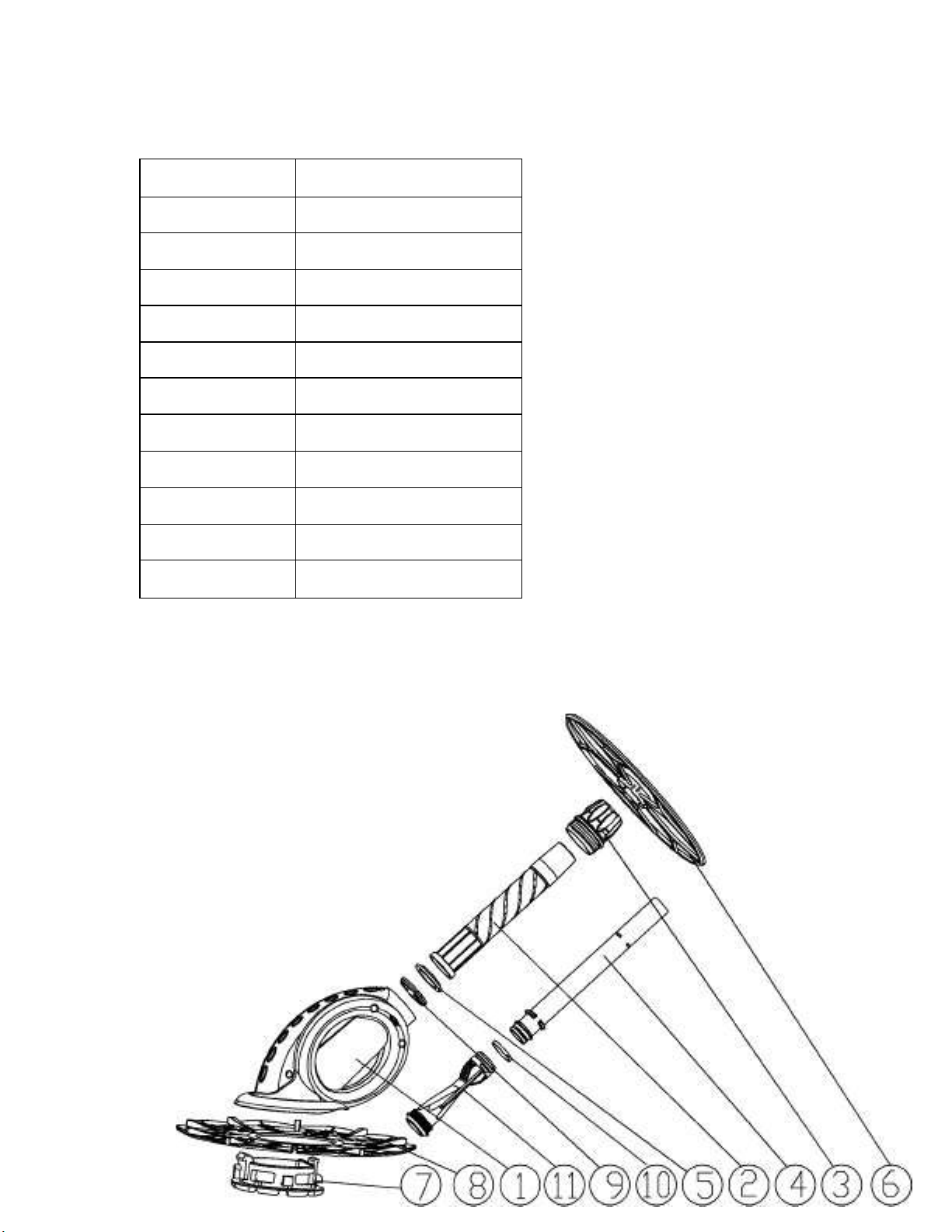
PARTS DIAGRAM
ITEMNO.
DESCRIPTION
1
Main Body
2
Outer Extension Pipe
3
Hand nut
4
Inner Extension Pipe
5
Thrust Washer
6
Deflector Wheel
7
Footpad
8
Disc
9
IEP Locator
10
Retaining Ring
11
Diaphragm
Table of contents
Popular Swimming Pool Vacuum manuals by other brands


GRE
GRE Evolution AR208201 operating instructions

Zodiac
Zodiac SpaWand quick start guide

Polaris
Polaris 3900 Sport quick start guide

Pool Blaster
Pool Blaster iVAC 50 quick start guide

Kreepy krauly
Kreepy krauly Pool-cleaning system user manual

Pentair
Pentair KREEPY KRAULY PROWLER 820 Installation and user guide


