CTE VL3 FM User manual

Technical And User Manual VL3 2500W FM AMPLIFIER
VL3 FM Radio Amplifier
User Manual
Issued: January 2008 -Version 3
CTE Digital Broadcast
Via Gadames 93 - 20151
Milano (Italy)
This document may be duplicated or otherwise used or its contents made known to third parties only
with permission of the originator or other authorized people.
Infringements constitute an offence and are subject to claim for damages.
All rights reserved for patenting or utility model registration.

VL3 2500W FM AMPLIFIER
CTE Digital Broadcast 2
VL3 FM Radio 2500W amp.
88 - 108 MHz
The VL3 is a solid state FM amplifier with
2500W output power using MOSFET devices of
last generation. The RF amplification stage is
separated from the Power Supply Unit in order
to simplify the service and installation
procedures. Moreover, the amplifier is equipped
with a remote control interface that satisfies all
the standards regularly used in the Broadcast
field
•2500W Output Power
•High Efficiency And Reliability
•Connections for N+1 System
•Easy Maintenance
•RS232 and RS485 ports
•LAN and Parallel Remote Connection
Technical Characteristics
RF Unit
Frequency Range 88-108Mhz
Required Input Power 60W (typical < 50W) ; N female
Output Power 2500W ; 7/8 flange
Efficiency Typical 60%
Dimensions rack 19” 5U 35kg
Power Supply Unit
Mains 400 V Three-phase (with null and ground)
230 Single-phase
Power Supply Composition Rack modular n°3 PS 1800W Sinlge-phase
Dimensions rack 19” 2U 13kg
Type Switching Single-phase
PFC PFC active type PF 0,98
REMOTE CONTROL
Analogue Parallel Interface DB15
RS233 PC
RS485 BUS DATI
LAN Ethernet TCP/IP ; SNMP

VL3 2500W FM AMPLIFIER
CTE Digital Broadcast 3
GENERAL INDEX
1 GENERAL SAFETY AND WARNING RECOMMENDATIONS ................................................ 4
1.1 SAFETY SUGGESTIONS ....................................................................................................... 4
1.2 GENERAL SAFETY RECOMMENDATIONS ...................................................................... 5
1.3 GOOD PRACTICES ................................................................................................................ 5
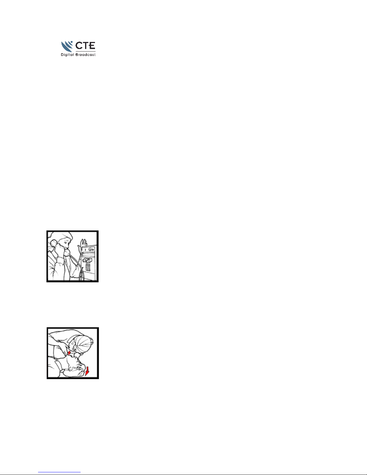
1.4 FIRST AID IN CASE OF ELECTRICAL SHOCK ................................................................. 6
1.5 EMERGENCY RESUSCITATION TECHNIQUE.................................................................. 6
1.6 TREATMENT FOR BURNS ................................................................................................... 8
1.7 WARNING INSTRUCTION.................................................................................................... 9
1.8 VL3 WARNING:.................................................................................................................... 10
2 VL3 General Description................................................................................................................ 12
2.1 Amplifier composition 2500W ............................................................................................... 12
2.2 VL3 BLOCK DIAGRAM...................................................................................................... 13
2.3 Front Panel Description .......................................................................................................... 14
2.4 RF Unit Description................................................................................................................ 16
2.4.1 RF 2500W Module.......................................................................................................... 16
2.4.2 1300W RF Module Description...................................................................................... 18
2.5 Low Pass Filter and Directional Coupler................................................................................ 19
2.6 Ext Interface............................................................................................................................ 20
2.7 General Controller Circuit ...................................................................................................... 20
2.8 Fuse board............................................................................................................................... 21
2.9 Power Supply UNIT Description............................................................................................ 21
2.9.1 Power Supply Board Description.................................................................................... 23
2.9.2 Power Supply Protections ............................................................................................... 24
3 Putting in operation Instructions..................................................................................................... 26
3.1.1 Unpacking ....................................................................................................................... 26
3.1.2 Connections..................................................................................................................... 26
3.1.3 Mains line power cord connection.................................................................................. 27
3.1.4 DB15 Parallel connection PIN Specification.................................................................. 28
3.1.5 Turning the system ON ................................................................................................... 28
3.1.6 Cares and maintenance.................................................................................................... 29
3.1.7 Menu Display.................................................................................................................. 29
4 Mechanical Dimensions.................................................................................................................. 34
5 Technical Specifications ................................................................................................................. 35
6 File schematics diagram.................................................................................................................. 36

VL3 2500W FM AMPLIFIER
CTE Digital Broadcast 4
1 GENERAL SAFETY AND WARNING RECOMMENDATIONS
1.1 SAFETY SUGGESTIONS
Regardless of how well electrical equipment is designed, personnel can be exposed to dangerous
electrical shock when protective covers are removed for maintenance or other activities. Therefore, it
is incumbent on the user to see that all safety regulations are consistently observed and that each
individual assigned to the equipment has a clear understanding of the first aid related to electrical
shocks. (see next pages)
In addition these safety practices must be followed:
•Do not attempt to adjust unprotected circuit controls or to dress leads with power on.
•Always avoid placing parts of the body in series between ground and circuit points.
•To avoid burns, do not touch heavily loaded or overheated components without precautions.
•Remember that some semiconductor cases and solid-state circuits carry high voltages.
•Do not assume that all danger of electrical shock is removed when the power is off. Charged
capacitors can retain dangerous voltages for a long time after power is turned off. These
capacitors should be discharged trough a suitable resistor before any circuit points are touched.
•Don't take chances. Be fully trained. CTE International equipment should be operated and
maintained by fully qualified personnel.
•Do not service alone and do not perform internal adjustments of this unit unless another person
capable of rendering first aid and resuscitation is present.
•Some components used in the construction of this equipment contain Beryllium Oxide (BeO).
This substance is harmless as it is, but becomes highly dangerous if it is ground to powder.
Special procedures of disposal must be observed in case of failure of these devices.
NOTE: This section is not intended to contain a complete statement of all safety precautions which
should be observed by personnel in using this electronic equipment or others.
CTE International shall not be responsible for injury or damage resulted from improper procedures or
from using it by improperly trained or inexperienced personnel.

VL3 2500W FM AMPLIFIER
CTE Digital Broadcast 5
1.2 GENERAL SAFETY RECOMMENDATIONS
When connecting the equipment to the power , please follow these important recommendations:
•This product is intended to operate from a power source that will not apply more than 10% of
the voltage specified on the rear panel between the supply conductors or between either supply
conductor and ground. A protective-ground connection by way of the grounding conductor in
the power cord is essential for safe operation.
•This equipment is grounded through the grounding conductor of the power cord. To avoid
electrical shock, plug the power cord into a properly wired socket before connecting to the
product input or output terminals.
•Upon loss of the protective-ground connection, all accessible conductive parts (including parts that
may appear to be insulating) can render an electric shock.
•To avoid fire hazard, use only the fuse of correct type, voltage rating, and current rating. Refer
fuse replacement to qualified service personnel.
•To avoid explosion, do not operate this equipment in an explosive atmosphere.
•To avoid personal injury, do not remove the product covers or panels. Do not operate the
product without the covers and panels properly installed.
1.3 GOOD PRACTICES
In maintaining the equipment covered in this manual, please keep in mind the following, standard good
practices:
•When connecting any instrument (wattmeter, spectrum analyzer, etc.) to a high frequency
output, use the appropriate attenuator or dummy load to protect the final amplifiers and the
instrument input.
•When inserting or removing printed circuit boards (PCBs), cable connectors, or fuses, always
turn off power to the affected portion of the equipment. After power is removed, allow
sufficient time for the power supplies to bleed down before reinserting PCBs.

VL3 2500W FM AMPLIFIER
CTE Digital Broadcast 6
•When troubleshooting, remember that FETS and other metal-oxide semiconductor (MOS)
devices may appear defective because of leakage between traces or component leads on the
printed circuit board. Clean the printed circuit board and recheck the MOS device before
assuming it is defective.
•When replacing MOS devices, follow standard practices to avoid damage caused by static
charges and soldering.
•When removing components from PCBs (particularly ICs), use care to avoid damaging PCB
traces.
1.4 FIRST AID IN CASE OF ELECTRICAL SHOCK
If someone seems unable to free himself while receiving an electric shock, turn power off before
rendering aid. A muscular spasm or unconsciousness can make a victim unable to free himself from the
electrical power.
If power cannot be turned off immediately, very carefully loop a length of dry non-conducting
material (such as a rope, insulating material, or clothing) around the victim and pull him free of the
power. Carefully avoid touching him or his clothing until free of power.
1.5 EMERGENCY RESUSCITATION TECHNIQUE
Step 1
Check the victim for unresponsiveness. If there is no response, immediately call for medical
assistance, and then return to the person.
Step 2
Position the person flat on their back. Kneel by their side and place one hand on the forehead and the
other under the chin. Tilt the head back and lift the chin until teeth almost touch. Look and listen for
breathing.

VL3 2500W FM AMPLIFIER
CTE Digital Broadcast 7
Step 3
If not breathing normally, pinch the nose and cover the mouth with yours. Give two full breaths. The
person's chest will rise if you are giving enough air.
Step 4
Put the fingertips of your hand on the Adam's apple, slide them into the groove next to the windpipe.
Feel for a pulse. If you can not feel a pulse or are unsure, move on to the next step.
Step 5
Position your hands in the center of the chest between the nipples. Place one hand on top of the other.
Step 6
Push down firmly two inches. Push on chest 15 times.
CONTINUE WITH TWO BREATHS AND 15 PUMPS UNTIL HELP ARRIVES.

VL3 2500W FM AMPLIFIER
CTE Digital Broadcast 8
1.6 TREATMENT FOR BURNS
•Continue treat victim for electrical shock.
•Check for points of entry and exit of current.
•Cover burned surface with a clean dressing.
•Remove all clothing from the injured area, but cut around any clothing that adheres to the skin and
leave it in place. Keep the patient covered, except the injured part, since there is a tendency to chill.
•Splint all fractures. (Violent muscle contractions caused by the electricity may result in fractures.)
•Never permit burned surfaces to be in contact with each other, such as: areas between the fingers or
toes, the ears and the side of the head, the undersurface of the arm and the chest wall, the folds of
the groin, and similar places..
•Transport to a medical facility

VL3 2500W FM AMPLIFIER
CTE Digital Broadcast 9
1.7 WARNING INSTRUCTION
INTRODUCTION
The transmitter or the equipment that this manual is referred to is developed, produced and tested
following the relevant safety standards EN 602125.The following safety instruction advice the operator
about the dangerous operation concerning the equipment. The user must be read the safety instruction
contained in the manual and they must follow them. As mentioned on the safety rules qualified
technical staff only can operate this equipment. CTE declines any responsibility for damages caused
by an improper use or improper setting up performed by inexperienced staff, not qualified or operating
with instruments or tools not in compliance with safety set of rules.
The staff in charge, besides being technically qualified, must be trained in first aid in case of
emergency or accident (reanimation, heart massage, mouth to mouth respiration, etc.).
Before going on with the operations to be performed, it is necessary to know the position of the general
electric switch and the one of the extinguishers, which have to be used very quickly if necessary.
CHECKING OF SAFETY CONDITIONS
The following connection and verify must be observed to guarantee the safety for the personnel.
•Correct connection with the antenna cable
•Correct connection with a mains line cable
•Correct connection with a ground cable (EARTH CONNECTION)
•Verify that the ambient where the equipments is installed is in compliance with the specification
declared by the manufacturer : altitude, humidity, temperature.
AC/DC LINE WARNING
This equipment is working with dangerous high voltage and current. Any voltage present inside this
equipment can be potentially dangerous for personnel. The technical staff designed for the service and
repair operation must be qualified and they must take the appropriate safety measures stated on safety
rules.
SERVICE and OPERATIONAL WARNING
The technical staff in charge of the service operations inside the equipment with any cover removed
must check that the mains line is disconnected. After the service operation is completed the cover must
be correctly mounted before the connection with the mains line. The high voltage is present on the
mains stage of the equipments also when the mains switch is in OFF positions and the mains line cable
is connected.
If it is really necessary and after authorization of CTE very qualified technical staff only can work with
on live parts. In this special case special safety precautions must be taken. CTE declines any
responsibility if any safety rule is not respected. The replacement of the accessible fuse must be made
with the transmitters turned off and using a fuse with the identical characteristics only as specified by
the manufacturer.

VL3 2500W FM AMPLIFIER
CTE Digital Broadcast 10
1.8 VL3 WARNING:
The VL-3 should be placed in a suitable cabinet; after this operation, the front panels will be the only
parts accessible without using tools.
Special care should be paid to the lithium battery placed inside the RF power unit: when exhausted, it
must be replaced with a new battery of the same type, whereas the disposal of the exhausted battery
will be in accordance to the normative.
The distributing frame of the mains connected to the equipment must be protected against short
circuits. (e.g. with magneto-thermal switch or fuses) . The connecting cables will be 4 mm² (AWG 10)
or of higher section if possible.
The general conditions of the shelter and the overall maintenance of the equipment should provide its
adequate safety. In the event of their intervention and in any case periodically, the protection devices
should be inspected and controlled by skilled and authorized personnel. All the safety and protection
devices must never be submitted to alteration, and they will be disconnected only at the time that their
replacement will be necessary.
The cooling fans of the equipment must be periodically (about 2 years) replaced. (120x120 cod.
E09030 , 80x80 code E09040 )
The air filters must be periodically cleaned and replaced if damaged.
Once the installation of the system including cables and antennas is completed, it must be in
compliance with the EMF clauses advised in the 1999/519/EC normative.

VL3 2500W FM AMPLIFIER
CTE Digital Broadcast 11
WARNING SYMBOLS
The following symbol are used on this equipment to advise the user about the most important
dangerous parts.
DANGER SHOCK HAZARD
PE TERMINAL
WARNING ! TOXIC
HAZARD
THESE DEVICES
CONTAIN BERYLLIUM
OXIDE
OBSERVE SAFETY
INSTRUCTIONS !
Certain devices (for example
the RF final circuits
MOSFETS) contain
Beryllium Oxide BeO; these
components must not be
broken, crashed or heated.
This oxide passes through the
common systems of filtering,
including the respiratory
apparatus. The prolonged
inhalation at high degrees
causes poisoning with
respiratory apparatus
paralysis, until death.

VL3 2500W FM AMPLIFIER
CTE Digital Broadcast 12
2 VL3 General Description
2.1 Amplifier composition 2500W
The VL-3 FM Radio amplifier is a wide band 2,5KW FM solid state amplifier composed by two 19U
racks, mechanically independent: the RF Unit and the Power Supply Unit. The main connections
between the two units are:
1The 50Vdc feeding cable.
2The AUX cable, used to connect the ± 20Vdc to the control signal necessary for the management of
the equipment and provided by the microprocessor Board placed on the RF UNIT.
COMPOSITION VL3 ( rear view)

Technical And User Manual VL3 2500W FM AMPLIFIER
2.2 VL3 BLOCK DIAGRAM
Vcc1
Vcc2
Detect Unb.
1250W
1250W
BPF Directional
Coupler
RF Input
50W max
RF out
2500W
RF UNIT 2.5KW
PS1 1800W
Scheda
Shunt
Vcc1
Vcc2
PS2 1800W
PS3 1800W
L1
L2
L3
3 x PS 1800VA

Technical And User Manual VL3 2500W FM AMPLIFIER
2.3
Front Panel Description
RS232
Stand-By Alarm ALC VSWR
RF PROBE
19"
5U
Amplifier Front Panel
Amplifier Rear Panel
1
2
3
4
5
6
7
8
9
10 11
12

VL3 2500W FM AMPLIFIER
CTE Digital Broadcast 15
Power Supply Unit Front view
Power Supply Unit Rear view
N° Description N° Description
1 RS232, communication port for internal use 11 50 V_dc Connection To The Power Supply Unit,
Cable Included On The Box
2 Stan-By(Orange): indication of Stand-By status
Alarm(Red): indication of General Alarm
ALC(Green): Automatic Loop Control is ON. Must
be ON .
VSWR: ON if 10% of Reflection Power is present
12 RF input, N female connector Max 100W
3 Display LCD 13 Grid with air filter
4 Keyboard 14 LED POWER SUPPLY STATUS
GREEN : Normal Condition
ORANGE: Stand-BY
RED: Alarm
5 RF Probe, -50dBc not directional 15 Output 230Vac for very low power auxiliary
equipment
6 Grid with air filter 16 ON/OFF MAINS BREAKER
7 Fans for RF unit 17 50 V_dc Connection To The Power Supply Unit,
Cable Included On The Box
8 Fans for internal load, Active only in presence of
unbalanced power. 18 AUX PS: Used For Power Supply Connection
9 Output connector, Flange 7/8. 19 Input for the Mains Line power cord
10 External Interface
AUX PS: Used For Power Supply Connection
DB15: Used for remote analogue control
LAN: RJ45 for TCP/IP ans SNMP connection
RS485: Internal BUS CONNECTION
1
3
1
9
1
5
14
18
17
1
6

VL3 2500W FM AMPLIFIER
CTE Digital Broadcast 16
2.4 RF Unit Description
The RF unit is composed by :
1Input Splitter –3dB 90°
2Two RF Module 1300W (+ dedicate RF Control)
3Combiner -3dB 90°
4Unbalanced Dummy load Max 800W
5Low Pass Filter (Typical harmonic suppression –90dBc)
6High directivity Directional Coupler with two separate head probes (selectivity > 30dB)
7Microprocessor Board
8External interface end remote control
9Cooling system composed by two redundant fans Type H3 PAPST, 280 m3/h each
2.4.1 RF 2500W Module
The RF Unit is placed in a 19” standard 5U rack, with 700mm depth and a total weight of 40Kgs. only.
Inside it, two RF Modules of 1300W nominal power are situated, using four MOSFET of new
generation SD2942. Every module is equipped with a control loop that guarantees maximum reliability
and high speed interventions to protect the equipment against over-temperature or excessive SWR. The
protections are independent with respect to the microprocessor.
The input is made by a 3dB 90° hybrid divider splitting the RF power coming from the FM driver
modulator. The output power of the two modules is connected to a - 3dB 90° hybrid combiner which
adds the RF power that arrives from the two 1300W modules. The output power of the 90° combiner
is placed between the two RF 1300W modules that are mounted in parallel position. This mechanical
solution guarantees great compactness and easy accessibility to the electronic parts. Moreover, the RF
2500W unit includes a built-in dummy load that in case of breakdown of one module assures continuity
of on-air operation. The unbalanced dummy load can stand up to 800W continuous.
-3dB 90° 2500W Combiner
OUT 2500W
INPUT 1250W
Unbalanced Load

VL3 2500W FM AMPLIFIER
CTE Digital Broadcast 17
The Output of the Combiner is connected to the low-pass filter that eliminates the residual of the
harmonic frequencies, providing typical suppression figures of 90dBc. The output of the low-pass filter
is connected to the directional coupler, composed by two separate head probes equipped with the
necessary devices to keep under control the RF power level and to convert it in DC. The DC voltage is
used to monitor the direct and reflected power from the Menu, but for the protections of the ALC and
VSWR figures as well. The RF output is terminated with 7/8” EIA Flange.
Picture of the RF MODULE, 2,5KW. Detail of the RF module, 1,3KW
Nominal Power 350W

VL3 2500W FM AMPLIFIER
CTE Digital Broadcast 18
2.4.2 1300W RF Module Description
The 1,3 kW modules is composed by the following stages:
•Power Splitter
•RF Amplifier
•Output Combiner
•Control Circuit
Power Splitter
The input power from the exciter is applied to a Wilkinson splitter; the signals on the outputs are in
phase with each other.
Both outputs are connected to the input of two 3 dB couplers.
The outputs 1 and 2 of the 3dB couplers are out of phase by 90° but they have the same power, just like
the
outputs 3 and 4.
The resistive termination resistors R1, ..., R4 absorb the unbalanced power when one of the SD2942
devices fails.
RF Amplifier
The amplifier circuit is composed of four identical base modules. The input matching of the active
device SD2942 composed of two FET is realized by means of the transformation ratio 4:1 of
transformer T1, by the capacitors C1, C2 and by the inductor L1.
The resistors R1 and R2 connected between the two gates of SD2942 increase the margin of stability of
the amplifier , at the same time providing an SWR figure that is acceptable over the whole operating
frequency band.
The two FET composing the SD2942 operate in push pull mode.
The line connected between the two drains compensates the capacitate part of the output impedance. by
the adapter circuit composed of C5, C7, L2 and L3, the ensuing impedance is raised by the
transformation ratio 1:4 of the transformer T2 up to the value of 50Ω. The parallel resonating circuit
composed of C6 and L2 is calculated so as to lower the value of the 2nd harmonic component
generated by the amplifier.
The gates of the two FET devices are connected, by means of R8 and L6, to the bias circuit. The direct
voltage on the gates are adjusted by means of the trimmer RV1.
The NTC which is located on the case of the active device, compensates the variation of the bias figure
according to the operating temperature. Through the point 13 connected to the control circuit and by
means of an appropriate negative voltage, it is possible setting at zero the level of the RF output power
in the event of any operating troubles detected by the control circuit itself.
The toroidal ferrite cores of the output transformer may be damaged by strong magnetic fields created
by electrical currents. This situation may arise in the event of failure of a FET device.

VL3 2500W FM AMPLIFIER
CTE Digital Broadcast 19
Output Combiner
The power coming from the four SD2942 stages are sent to the input of two 3dB couplers whose output
are in phase with each other.
A Wilkinson type coupler adds these outputs. In the output line, a directional coupler detects the figures
of forward and reflected output power. The resistive terminations R1, R3, R5 and R6 absorb all the
unbalanced power. At the ends of the terminations there are three detectors. Their outputs, just as the
outputs coming from the forward and reflected power, are sent to the control circuit.
RF Control Circuit
The protection function of the four SD2942 devices is obtained by the Control Circuit.
The amplifier is protected against excessive SWR, excessive unbalanced powers and overheating. The
signal WR coming from the "reflected power detector", is amplified by U2A and will reach the
comparator U2D.
In case the reflected power will exceed the pre-set value, established by the resistive trimmer RV1, the
comparator U2D sets its output representing an excessive reflected power level.
The signal SB3 coming from the high impedance unbalanced detector is buffered by OP AMP U1 a
and transformed in low output impedance.
The signal of unbalanced SB1, SB2, SB3) previously processed, are offered to the three diodes D7, D8,
D9 to the input of buffer U1B.
The output of U1B is connected to the comparator U1D whose output represents excessive internal
unbalanced power error. The intervention protection level of SB1 SB2 SB3 can be adjusted by the
resistive trimmers RV2 RV3 and RV4.
When the temperature level of the heat-sink reaches the intervention threshold (80°C), the temperature
chip sensor placed at the centre of the same heat-sink transmits a signal to the microprocessor that in
this case will turn the Amplifier off.
The constant current generator made by transistor Q3 and surrounding components, feeds the diodes
D4 and DZ1. On the diodes, a voltage of 10V should be constantly present.
This is the bias and the control voltage of the basic module.
The previous described are led through D7 coming into the basis of the Darlington pair Q1 and Q2, in
case of intervention, can regulate the control voltage to a level of about -12V which totally cuts the
output power of the module. If the control voltage (-15V auxiliary supply) fails, the general control by
means of the microprocessor turns the amplifier off.
2.5 Low Pass Filter and Directional Coupler
The low pass filter is elliptic type with minimum inductor shapes Cauer-Chebyshev. A directional
coupler is placed on the output of the filter, which gives the tension to measure the direct and reflex
power. On the same line a signal for an “RF Proble” is taken at 40bD equalized in band .

VL3 2500W FM AMPLIFIER
CTE Digital Broadcast 20
Low Pass Filter and Directional Coupler
2.6 Ext Interface
The Ext. Interface Board makes the interface functions between the VL3 and others external unit:
-Remote Control
- Connection to external control unit
By means of the connector C8, it is possible to use the 485 serial; on the EC4 connector (parallel
interface) the analogue and the digital signals are available at a voltage figure between 0 and +5V; by
means of the lan module U10 it is possible monitoring on a web-page all the functions of the
equipment. On this Ext Interface board, three identical DC-DC converters area also allocated: they
supply the necessary power to the cooling fans of the RF power modules and of the load.
2.7 General Controller Circuit
The Controller Circuit, placed on the rear side of the front panel has the following functions:
-Equipment control achieved by means of a Microprocessor M3062
-User Interface by a dedicated display LCD
- Setting and alarm threshold programming
Along with its own controller functions, the “General Controller Circuit” board also provides the
function of link for the several internal boards. The Controller is equipped with a flash memory and
allows via RS232 port any up-grades relevant to the new functions of the software. The I.C. RTC4543S
provides the function of clock-data. In case of a black-out event, all the data previously set are
memorized by means of the I.C. ST93C86. The communication with other external devices is
established by the I.C. UDS14C232 via the RS232 port, and by the I.C. DS75175 via the RS485 port.
The I.C.’s LM336 and LM358 are the interfaces between the temperature sensor placed on the power
amplifier and the input of the microprocessor.
This manual suits for next models
1
Table of contents
Popular Amplifier manuals by other brands

SUPRO
SUPRO BLACK MAGICK REVERB user manual

Rupert Neve Designs
Rupert Neve Designs Portico 5016 user guide

qtxsound
qtxsound SPL400 instruction manual

Cyrus
Cyrus 7 User instructions

Greg Hanks Design
Greg Hanks Design BA-660 Operation and service manual

Bellman & Symfon
Bellman & Symfon Audio Maxi BE2020 manual