manuals.online logo
Brands
  1. Home
  2. •
  3. Brands
  4. •
  5. Cub Cadet
  6. •
  7. Lawn Mower
  8. •
  9. Cub Cadet 1200 User manual

Cub Cadet 1200 User manual

International Cub Cadet 1250, 1450,
and 1650 Tractors
TO
THE OWNER
I
nside Cover
DELIVERY SERVICE
SERVICE MANUAL INFORMATION
Brake pedal
Speed control lever
Startingthe tractor
Release lever
Stopping,the tractor
CONTENTS
1,2 EGUIPME'NT LIFT HANDLE 14
SER1AL NUMBER LOCATION 3
Heightadjustment
INTRODUCTION
3
HITCHING EOU1PMENT TO THE
TRACTO'R
WO'RK SAFELY-FOllOW THESE
RULES 15
4
INSTRUMENTS AND CONTROLS 5,6 0 rawbar
Three-point hitch
aEFOREOPERATING YOUR NEW
TRACTQ,R: REAR POWER TAKE-OFF
16
7
0 peratrng the rear power
take-off wrth the tractor
standing stiII
7,8:
OPERATING THE ENGINE
Operating the rear power
take-off with the tractor
in motion
Throttle lever
Governor
Lifting, the hood
Starting the engine
Stopping the engine FRONT POWER TAKE-OFF 17
FUEL SYSTEM 9 10
,Operating the front power
take-off clutch
Fuel shut-c.ff valve
Carburetor adjustments Adjusting the power take-off
clutch
10 to 14 ELECTRIC LIFT
DRIVING
THE TRACTOR 17, 18
HYDRAULIC LIFT 19
Adjusting the seat
Clutch and brake pedal
Locking the brake ENGINE COOLING AND AI R
CLEANER 20
International Cub Cadet ROO,1000,
and 1200 Tractors Engine cooling
Dry type air cleaner
Clutch-brake pedal
Gearshift lever
Starting the tractor
Stopping the tractor
Creeper shift lever
Operating the creeper drive
CONTENTS
ELECTRICAL SYSTEM STORING THE TRACTOR20 to 22 28
Removing from storage
EXTRA EOU1PMENT AN D
ACCESSO R1ES 29
TROUBLE SHOOTING
Ignition swrtch
Safety starting switch
Charge indicator
Hour meter
Spark plug
Motor generator 29,30
LUBRICATION 31,32
Motor generatorbelt
lights
Fuse LUBRICATION TABLE 33
LUBRICATION GUIDE
PNEUMATIC
TIRES 23 International Cub Cadet 800,
1000 and 1200 Tractors 34 to 36
LUBRICATION GUIDE
Rear tires
Care of tires
Inflation
Operating pressure for tires
Mounting tires on the rim
Rear wheel weights
Tire chains
Overloading
International Cub Cadet 1250,
1450 and 1650 Tractors 37 to 39
SPECIFICATIONS 39 to 42
FRONT WHEELS 24
Front quick attaching latch
Front wheel toe-in
Turning radius
CLUTCH-BRAKE
International Cub Cadet 800, 1000,
and 1200 Tractors 25,26
Adjusting the clutch
Adjusting the brakes
BRAKES
I
nternational Cub Cadet 1250, 1450
and 1650 Tractors 27
Adjusting the brakes
-2-
This symbol is used to call your attention to instructions
concerning your personal safety. Be sure to observe and
following these instructions.
Disengageall clutches and shift into neutral beforestarting
the engine. Watch out for traffic when crossing or near
roadways.
To avoid injury, disengage power to any attach-
ments and stop engine before leaving operator',s
seator making any repairs or adjustments.
When using any attachments, never direct discharge
of material toward by-standers nor allow anyone
near the machine while in operation.
Know the controls and how m stop quickly.
READ THE OPERATOR'S MANUAL. Handle gasoline wfth care -it is highly flammable: -
A. Use approved gaso1ine container. B. Never
remove the fuel tank cap or fiJ1the fuel tank when
the engine is running, is hot, or indoors. Also, do
not smoke when working around inflammable fuel.
Wipe up spilled gasoline. C. Replace gasoline cap
securely.
To avoid an accident or injury, do not allow
children or adults to operate the equipment
without proper instruction.
Clear work area of objects which might be p.icked
up and thrown. During operation do not run the engine in confined
area such as storage building any longer than is
necessaryfor immediate moving of the tractor'outside
into the air.
Disengagepower to any attachment when trans-
porting or not in use.
To prevent injury, do not carry passengersor give
rides. Keepchildren, pets, and by-standersa safe
distanceaway.
Keep machine in good operating condition and
keep safety devices in place. Use guards or shields
asinstructed in Operator's Manual
To prevent an accident, always disengage the
power take-off, shift transmission into neutral, set
the parking brake, stop the engine, and remove
ignition key when leaving the machine unattended.
1t is recommended that the machine be stopped
and inspected for damage after striking a foreign
object and that any damage be repaired before
restarting and operating the machine.
Always turn ignition "OFF", depress the brake
pedal, and set the brake pedal lock before working
on the machine. Disengageall implements and shift
the transmission into neutral.
Reduce speed on slopes and in sharp turns to
prevent tipping or lossof control.
Stay alert for holes in terrain and other hidden
hazards.
Before backing the tractor, always look for ob-
stacles or bystanders in the area where the tractor
will move.
REMEMBER -A careful operator is the best
insurance against an accident.
Avoid Overturns -Back the tractor up the steepest
portion of the hill to be mowed! If the tractor
cannot do this, the hill is too steep for safe
operation. When mowing hills, cut down the face
of the hill rather than across to avoid side tipping.
Also, avoid sudden starts, stops, and turns,
especially on steepslopes to avoid an upset.
Use care when pulling loads or using heavy
equipment: -A. Use only approved hitch points. B.
Limit loads to those you can safely control. C.
Don't turn too sharp, and use care when backing.
D. Use counterweight or wheel weights when
suggestedin Operator's Manual.
4
FUELSYSTEM
CARBURETOR ADJUSTMENTS -Continued If the engine shows a sooty exhaust and is sluggish
under load, the high speed mixture istoo rich. The
high speed adjustment screw must be turned
clockwise 1/8 turn at a time until the condition is
corrected.
NOTE: To prevent possible damage to the carbure-
tor needles, be very careful closing the carburetor
needles before basic adjustments are made. Im-
proper adjustment of the carburetor may result in
engine damage. Adjusting the Idle Adjustment Screw
Adjusting the High-Speed Adjustment Screw After the high speed adjustment screw isadjusted,
it may be necessaryto readjust the idle adjustment
screw aseach affects the other.
Turn the high speed adjustment screw counter-
clockwise approximately two turns from the closed
position and start the engine. Close the idle adjustment screw to its seat by
turning it clockwise; then open it one turn. Start
the engine and operate it at fast idling speed
(without any load) until thoroughly warm.
Be sure the choke is fully open (knob fully in)
when adjusting.
After the engine has reached normal operating
temperature, place the throttle lever in the fast
position and turn the high speed adjustment screw
clockwise to the leanest mixture that will allow
satisfactory acceleration and steady governor
operation. Then, turn counterclockwise to the
richest mixture that allows satisfactory operation.
The difference between the rich and lean points is
about 1/2 turn. Set the mixture to the rich end of
this range.
While the engine is running at fast idle speed, it is
advisable to screw in the throttle stop screw a few
turns to keep the engine from stopping when the
throttle lever is moved to the fully retarded
"SLOW" position. The engine will then be idling at
a fairly high speed and the throttle stop screw can
be backed out a little at a time until the desired
idle speed isobtained (1800 RPM).
If the engine missesor rolls while backing out the
throttle stop screw, the idle adjustment screw may
be adjusted in or out until the engine operates
smoothly. Speed up the engine for a few seconds;
then recheck the idle adjustment. A slight adjust-
ment in or out will give the smoothest idle.
If the engine missesand backfires under load, the
high speed mixture is too lean. The high speed
adjustment screw must be turned counterclockwise
1/8 turn at a time until the condition iscorrected.
PREPARING THE TRACTOR FOR EACH DAY'S WORK
Inspect the tires for general condition. See pa~ 25.
Check the crankcase oil level and add new oil if
necessary.Seepages32 and 33.
Clean the air cleaner element if necessary.See page
21.
10
DRIVINGTHETRACTOR
International Cub Cadet 800, 1000, and 1200 Tractors
free the tractor by speeding up the engine and
suddenly engaging the clutch. Try backing out
instead of going foward.
CLUTCH-BRAKE PEDAL
The combination clutch-brake pedal is used to
disengage the engine from the transmission when
shifting gearsand to actuate the brake to stop the
tractor. The pedal must be pressed all the way
down to activate the safety starting switch when
starting the engine.
CAUTION! To avoid possible injury, do
not carry passengersor give rides. Keep
children, pets, and bystanders out of the
area.
To disengagethe clutch, and apply the brake, press
the pedal all the way down. STOPPING THE TRACTOR
Disengage the clutch by pressing the pedal all the
way down. Move the gearshift lever to the "N"
position. Before dismounting always lock the
pedal, disengage the power take-off, and turn the
ignition "OFF".
GEARSHIFT LEVER
This lever is used to select various gear ratios
provided in the transmission. There are three
forward speeds and one reverse speed. Refer to
"SPECIFICATION", on page41. CREEPER SHIFT LEVER
STARTING THE TRACTOR The creeper drive (optional) provides a slower
speed in each respective gear, by a four-to-one
reduction in speed from direct drive. When the
creeper shift lever is all the way forward, it is in
direct drive, or all the way rearward, it is in creeper
drive.
Disengage the clutch by pressing the clutch pedal
all the way down, and releasethe brake lock. Move
the gearshift lever to the desired speed.
Start the tractor in motion by slowly releasing the
clutch pedal and moving the throttle lever to the
position where the engine operates best for the
load to be handled. OPERATING THE CREEPER DRIVE
To operate the tractor in creeper drive, depressthe
pedal and move the creeper shift lever all the way
rearward. Then select the transmission speed
desired and proceed as instructed under "Starting
the Tractor".
NOTE: When using power take-off operated equip-
ment, best performance is achieved with the
throttle lever in the "Fast" position.
NOTE: Do not shift gears while the engine clutch
isengaged or while the tractor is in motion. NOTE: Do not use a mid-point position on the
creeper drive as neutral. Neutral position must be
selected only with the standard transmission
gearshift lever.
NOTE: Do not rest your foot on the pedal while
driving the tractor, as this will result in excessive
clutch lining wear. The following table shows the speeds available in
each of the three forward gears and the reverse
gear.
Always be sure the rear wheels are free to turn.
Under any adverse conditons, do not attempt to
12
DRIVINGTHETRACTOR
1nternationalCub Cadet1250, 1450,and 1650Tractors
STARTING THE TRACTOR NOTE: Never operate engine with release lever in
(UP) position. Towing or pushing the tractor for
more than a few feet may result in transmission
damage.
1. Depress the brake pedal and release the brake
lock. Move the throttle lever to the position where
the engine operates best for the load to be handled.
2. Start the tractor in motion by moving the speed
control lever slowly forward or rearward as
described above.
STOPPING
THE TRACTOR
Move the speed control lever to the "N" position
or use the brake. Before dismounting always lock
the brake pedal and turn the ignition "OFF". Also,
disengagethe power take-off clutch lever.
RELEASElEVER
To push or move the tractor for a short distance,
the release lever, located on the right side of the
frame near the cam stop, must be held in the (up)
position and the speed control lever must be in the
"N" position.
CAUTION! To prevent injury or an
accident, do not carry passengersor give
rides. Keep children, pets, and by-
standers out of the area.
The lift handle is used to lift or lower equipment
used with the tractor. The equipment can be set in
multiple positions by depressing the button on the
top of the handle and releasing it when the desired
position is reached.
Lock cam into this position by turning knobclockwise.
If free handle travel between cam stop and fully
raised position is desired (Float Position), depress
the release button on top of the handle, press in
the lock button located at the front of the handle
and releasethe top button.
HEIGHT ADJUSTMENT
If a single implement height is normally used, the
handle may be adjusted to locate the desired
position by use of the cam stop. NOTE: To disengage the lift handle from the float
position, pull lift handle back slightly and depress
top button.
With lift handle in desired implement height
position, release cam by turning locking knobcounterclockwise.
Turn cam until it contacts tang. NOTE: Refer to the equipment manual for proper
hitching instructions.
14
OPERATING THE FRONT POWER TAKE-OFF
CLUTCH The clutch is factory adjusted and should not
require further adjustment under normal operating
conditions. However, if the clutch fails to operate
properly check asfollows:
The front power take-off clutch is an electric
clutch operated by a toggle switch on the left side
of the instrument panel. Check fuse on pedestal.
1. Move the throttle lever back to the medium or
"slow" position. Using a feeler gauge check the clearance. If the
clearance is not .015/.010 inches tighten the four
(4) self-locking nuts to obtain the proper clearance.
2. Flip the toggle switch on to the "ON" position. If the above procedure does not work, see your
I nternational Harvester dealer.
3.
Advance throttle to operating speed (full speed).
ADJUSTING THE POWER TAKE-OFF CLUTCH
CAUTION! To avoid an accident or
possible injury, always disengage all
clutches and shift into neutral before
starting the engine.
CAUTION! To avoid possible injury,
always disengage all clutches, shift the
transmission into neutral, depress the
brake, set the brake pedal lock and turn the igni-
tion "OFF" before working on the machine.
1. Self-locking nuts (4)
2. Feeler gaugeopenings (4)
The electric lift is a self-contained unit designed to
provide power with fingertip control for raising the
lowering mounted equipment.
The ~Iectric lift is available on all Cub Cadet
Tractors except the Models 1450 and 1650 which
is equipped with a hydraulic lift as standard.
17

This manual suits for next models

5

Other Cub Cadet Lawn Mower manuals

Cub Cadet SERIES 5000 5252 User manual

Cub Cadet

Cub Cadet SERIES 5000 5252 User manual

Cub Cadet 949 User manual

Cub Cadet

Cub Cadet 949 User manual

Cub Cadet GT 2554 User manual

Cub Cadet

Cub Cadet GT 2554 User manual

Cub Cadet CC 760 Use and maintenance manual

Cub Cadet

Cub Cadet CC 760 Use and maintenance manual

Cub Cadet 29HP Tank 53AJ8CTX750 Operating manual

Cub Cadet

Cub Cadet 29HP Tank 53AJ8CTX750 Operating manual

Cub Cadet 10M User manual

Cub Cadet

Cub Cadet 10M User manual

Cub Cadet LT1045 User manual

Cub Cadet

Cub Cadet LT1045 User manual

Cub Cadet CC 30 User manual

Cub Cadet

Cub Cadet CC 30 User manual

Cub Cadet 2182 User manual

Cub Cadet

Cub Cadet 2182 User manual

Cub Cadet 13AX91AT596 User manual

Cub Cadet

Cub Cadet 13AX91AT596 User manual

Cub Cadet 53AB5BBP750 Setup guide

Cub Cadet

Cub Cadet 53AB5BBP750 Setup guide

Cub Cadet 2206 User manual

Cub Cadet

Cub Cadet 2206 User manual

Cub Cadet CC 30 H User manual

Cub Cadet

Cub Cadet CC 30 H User manual

Cub Cadet 1515 User manual

Cub Cadet

Cub Cadet 1515 User manual

Cub Cadet RZT Series User manual

Cub Cadet

Cub Cadet RZT Series User manual

Cub Cadet 18M User manual

Cub Cadet

Cub Cadet 18M User manual

Cub Cadet RZT 54 User manual

Cub Cadet

Cub Cadet RZT 54 User manual

Cub Cadet Z-Force 44 User manual

Cub Cadet

Cub Cadet Z-Force 44 User manual

Cub Cadet TANK 60 User manual

Cub Cadet

Cub Cadet TANK 60 User manual

Cub Cadet 950-959 User manual

Cub Cadet

Cub Cadet 950-959 User manual

Cub Cadet 2084 User manual

Cub Cadet

Cub Cadet 2084 User manual

Cub Cadet Zero-Turn Commercial Riding Mower Professional Turf... Operating manual

Cub Cadet

Cub Cadet Zero-Turn Commercial Riding Mower Professional Turf... Operating manual

Cub Cadet 182 User manual

Cub Cadet

Cub Cadet 182 User manual

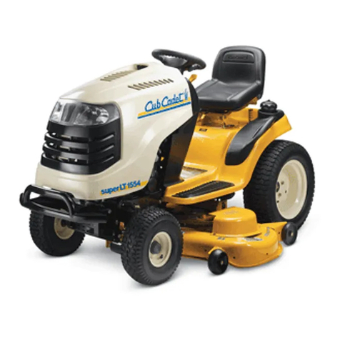
Cub Cadet SLT1550, SLT1554 User manual

Cub Cadet

Cub Cadet SLT1550, SLT1554 User manual

Popular Lawn Mower manuals by other brands

Toro Carefree 21040 Operator's manual

Toro

Toro Carefree 21040 Operator's manual

GGP CA/CAL 434-484-534 Operator's manual

GGP

GGP CA/CAL 434-484-534 Operator's manual

Poulan Pro PO550N21RH3 Repair parts manual

Poulan Pro

Poulan Pro PO550N21RH3 Repair parts manual

Exmark exmark 30" Operator's manual

Exmark

Exmark exmark 30" Operator's manual

Exmark LAZER Z S-SERIES Operator's manual

Exmark

Exmark LAZER Z S-SERIES Operator's manual

Havener Enterprises BRADLEY MOWERS 36 Owner's manual & parts list

Havener Enterprises

Havener Enterprises BRADLEY MOWERS 36 Owner's manual & parts list

Spearhead TWIGA COMPACT Handbook

Spearhead

Spearhead TWIGA COMPACT Handbook

Poulan Pro 96042002400 owner's manual

Poulan Pro

Poulan Pro 96042002400 owner's manual

Husqvarna YTH24K54 Operator's manual

Husqvarna

Husqvarna YTH24K54 Operator's manual

Poulan Pro 183249 owner's manual

Poulan Pro

Poulan Pro 183249 owner's manual

Craftsman 917.273321 owner's manual

Craftsman

Craftsman 917.273321 owner's manual

Yazoo/Kees KIKW36150 Operator's manual

Yazoo/Kees

Yazoo/Kees KIKW36150 Operator's manual

MTD Series 830 Operator's manual

MTD

MTD Series 830 Operator's manual

Ryobi RLM140SP user manual

Ryobi

Ryobi RLM140SP user manual

White Outdoor Products 183-387-190 owner's guide

White Outdoor Products

White Outdoor Products 183-387-190 owner's guide

Craftsman 247.27022 owner's manual

Craftsman

Craftsman 247.27022 owner's manual

BEFCO CYCLONE C30-CE5 Operator's manual

BEFCO

BEFCO CYCLONE C30-CE5 Operator's manual

MTD 140-760 10 H.P. owner's guide

MTD

MTD 140-760 10 H.P. owner's guide

manuals.online logo
manuals.online logoBrands
  • About & Mission
  • Contact us
  • Privacy Policy
  • Terms and Conditions

Copyright 2025 Manuals.Online. All Rights Reserved.